A&D AD-4971 User manual

1WMPD4002757B

© 2014 A&D Company, Limited. All rights reserved.
No part of this publication may be reproduced, transmitted, transcribed, or translated
into any language in any form by any means without the written permission of A&D
Company, Limited.
The contents of this manual and the specifications of the instrument covered by this
manual are subject to change for improvement without any notice and obligation on
the part of the manufacturer.

AD-4971
C
Contents
1. Introduction.................................................................................................................................... 5
1.1. Features ................................................................................................................................... 5
1.2. Safety Precautions................................................................................................................... 6
2. Description of Individual Parts...................................................................................................... 7
2.1. General View of the AD-4971 ................................................................................................. 7
2.2. Display Module ........................................................................................................................ 8
2.3. I/O Box (Input & Output Module) ............................................................................................ 8
3. Screen Operations........................................................................................................................ 9
3.1. Home Menu ............................................................................................................................. 9
3.2. Input Dialog Box....................................................................................................................... 9
3.2.1. Numerical Input Dialog Box࣭Password Input Dialog Box ........................................... 9
3.2.2. Character Input Dialog Box ........................................................................................... 10
3.2.3. Drop Down List Dialog Box ........................................................................................... 10
4. Basic Operations ........................................................................................................................ 11
4.1. Outline of Daily Operations ................................................................................................... 11
4.2. Turning the Power ON and OFF .......................................................................................... 12
4.2.1. Turning the Power ON................................................................................................... 12
4.2.2. Turning the Power OFF ................................................................................................. 12
4.3. Home Screen......................................................................................................................... 13
4.3.1. Inspection Screen .......................................................................................................... 13
4.3.2. Bar Graph Screen .......................................................................................................... 14
4.3.3. Lissajous Graph Screen ................................................................................................ 15
4.3.4. Inspection Settings Screen............................................................................................ 15
4.4. User Management................................................................................................................. 16
4.4.1. User Access Control ...................................................................................................... 16
4.4.2. Login................................................................................................................................ 16
4.4.3. Logout ............................................................................................................................. 17
4.5. Management of User List...................................................................................................... 18
4.5.1. Registering a New User................................................................................................. 18
4.5.2. Changing User Information ........................................................................................... 19
4.5.3. Deleting a User...............................................................................................................20
4.6. Target Product........................................................................................................................ 21
4.7. Product Registration .............................................................................................................. 21
4.7.1. Registering the Product ................................................................................................. 22
4.7.2. Copying the Product Data ............................................................................................. 23
4.7.3. Deleting the Product Data.............................................................................................. 23
4.7.4. Registering the Image of the Product ........................................................................... 24
4.8. Sensitivity Adjustment and Inspection Mode ....................................................................... 25
4.9. Calibration Mode.................................................................................................................... 27
4.10. Starting and Stopping the Inspection.................................................................................... 28
4.10.1. Starting the Inspection.................................................................................................... 28
4.10.2. Stopping the Inspection .................................................................................................28
4.11. History Management ............................................................................................................. 29

2
4.11.1. Inspection Results Screen............................................................................................. 29
4.11.2. Inspection History Screen.............................................................................................. 30
4.11.3. Calibration Results Screen ............................................................................................ 30
4.11.4. Operation History Screen .............................................................................................. 31
4.11.5. Error History Screen....................................................................................................... 31
5. Using a USB Flash Drive ........................................................................................................... 32
5.1. Using a USB Flash Drive ...................................................................................................... 32
5.1.1. Connecting a USB Flash Drive ..................................................................................... 32
5.1.2. Removing a USB Flash Drive ....................................................................................... 32
5.2. Storing the Results and the History ...................................................................................... 33
5.2.1. Storing the Inspection Results and the Calibration Results......................................... 33
5.2.2. Storing the Inspection History and the Operation History............................................ 34
5.3. Formatting a USB Memory ................................................................................................... 35
6. Printer .......................................................................................................................................... 36
6.1. Connecting to a Printer.......................................................................................................... 36
6.1.1. Connecting a Printer to USB Port ................................................................................. 36
6.1.2. Connecting a Printer to LAN Port.................................................................................. 36
6.2. Printing Results and History..................................................................................................36
6.2.1. Printing Inspection Results and History ........................................................................36
7. Reference Table of Screens and Menu Items .......................................................................... 37
7.1. Product Settings Screen (Product Edit Tab) ........................................................................ 39
7.2. Product Settings Screen (Product Settings Tab) ................................................................. 40
7.2.1. FAIL Limit Settings Screen ............................................................................................ 40
7.2.2. Inspection Phase Settings Screen (Phase Tab) ..........................................................42
7.2.3. Inspection Phase Settings Screen (Phase Tracking Tab)........................................... 42
7.2.4. FAIL Behavior Settings Screen ..................................................................................... 43
7.2.5. DO Map Settings Screen............................................................................................... 44
7.2.6. DO Behavior Settings Screen ....................................................................................... 45
7.2.7. Calibration Settings Screen ........................................................................................... 46
7.3. Settings Screen (Common Settings Tab)............................................................................. 46
7.3.1. DI Settings Screen (Configuration Tab) ........................................................................ 47
7.3.2. DI Settings Screen (DI Behavior Tab)........................................................................... 48
7.3.3. Function Settings Screen (Function 1 Tab) .................................................................. 48
7.3.4. Function Settings Screen (Function 2 Tab) .................................................................. 49
7.3.5. Function Settings Screen (Function 3 Tab) .................................................................. 49
7.3.6. Belt Speed Adjustment Screen ..................................................................................... 50
7.3.7. Count Settings Screen................................................................................................... 51
7.3.8. Connection Settings Screen (Serial Interface Tab)...................................................... 52
7.3.9. Connection Settings Screen (Modbus Interface Tab).................................................. 52
7.3.10. Printer Settings Screen.................................................................................................. 53
7.4. Settings Screen (System Settings Tab)................................................................................ 53
7.4.1. Date /Time Settings Screen ........................................................................................... 54
7.4.2. LCD Settings Screen ..................................................................................................... 54
7.4.3. LAN Settings Screen ..................................................................................................... 55
7.4.4. Speaker Settings Screen............................................................................................... 55
7.4.5. Backup/Restore Screen ................................................................................................ 56

3
7.4.6. USB Memory Settings Screen...................................................................................... 56
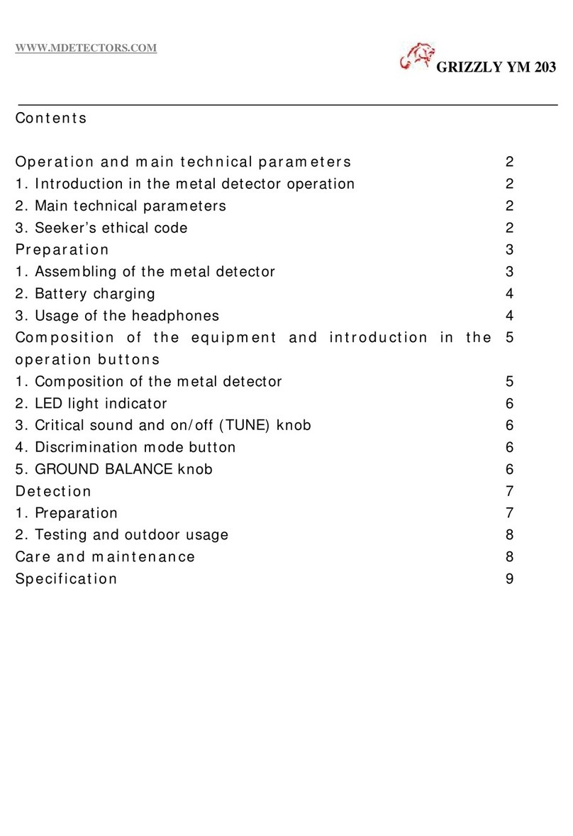
7.4.7. Language Settings Screen............................................................................................ 57
7.4.8. Software Version Screen ............................................................................................... 57
8. Modbus Communication............................................................................................................ 58
8.1. RTU Connection for Modbus ................................................................................................ 58
8.2. TCP Connection for Modbus ................................................................................................ 58
8.3. Reference Number for Modbus............................................................................................ 59
8.4. Address for Modbus .............................................................................................................. 59
9. General-Purpose I/O Terminals................................................................................................. 63
9.1. Layout of General-Purpose I/O Terminals............................................................................ 64
9.2. Circuits of General-Purpose I/O Terminals........................................................................... 64
9.2.1. Contact Input Terminals ................................................................................................. 64
9.2.2. Output Relay Terminals ................................................................................................. 65
9.2.3. Input and Output Terminals for Emergency Stop......................................................... 65
10. Maintenance and Cleaning........................................................................................................ 66
10.1. Ordinary Maintenance and Checks...................................................................................... 66
10.1.1. Check before Use (Inspection)...................................................................................... 66
10.1.2. Check after Use (Inspection)......................................................................................... 66
10.1.3. Periodical Check and Maintenance .............................................................................. 66
10.2. Cleaning ................................................................................................................................. 67
10.2.1. Light Dirt.......................................................................................................................... 67
10.2.2. Heavy Dirt ....................................................................................................................... 67
10.3. Maintenance of the Conveyor Belt ....................................................................................... 68
10.3.1. Removing the Conveyor Belt ........................................................................................ 68
10.3.2. Attaching the Conveyor Belt.......................................................................................... 69
10.3.3. Conveyor Belt Tracking and Tension Adjustment ........................................................ 69
11. Maintenance ............................................................................................................................... 70
11.1. The system file ....................................................................................................................... 70
11.1.1. Saving the System File .................................................................................................. 70
11.1.2. Restoring the System File.............................................................................................. 70
11.1.3. Resetting to Factory Settings ........................................................................................ 71
11.2. Messages............................................................................................................................... 72
11.2.4. Inspection Results Messages ....................................................................................... 72
11.2.5. Error Messages.............................................................................................................. 72
11.3. Treatment of an Error at System Initialization ...................................................................... 73
12. Specifications .............................................................................................................................. 74
12.1. List of Specifications............................................................................................................... 74
12.2. Dimensions ............................................................................................................................ 75
13. Appendix A : Configuration Examples....................................................................................... 76
13.1. Stop Belt Conveyor................................................................................................................ 76
13.1.1. Stop Immediately............................................................................................................ 76
13.1.2. Stop at the End of Belt Comveyor................................................................................. 76
13.2. Phase Tracking in calibration ................................................................................................77

4
13.3. Phase Tracking ...................................................................................................................... 77
13.4. Rotate Direction ..................................................................................................................... 78

1
Introduction
- 1.1
Features
5
1
1.
Introduction
This manual describes how the AD-4971
Metal Detector
works and how to optimize its performance. Read this
manual thoroughly before using the Metal Detector and keep it at hand for future reference.
The AD-4971
Metal Detector
detects metal contained within the product by measuring a change in the magnetic
fields surrounding the product. The methods it uses to detect metal are non-contact and non-destructive.
1.1.
Features
Display Unit
The AD-4971 is equipped with a 7-inch touch sensitive screen for easy operation.
The touch sensitive screen provides an interface which is simple to understand and operate.
Waterproof and Dustproof
The AD-4971 is equipped with a waterproof and dustproof frame in compliance with IP65.
Conveyor Belt
In comparison with timing belt drives, the gear-driven conveyor belt mechanism allows for easy maintenance
(removal, attachment, and tracking and tension adjustments).
Functions
The AD-4971 can divide products into ten groups and register a maximum of 100 products for each group (a total of
1000 products).
Product images can be uploaded from a connected USB flash drive.
The user registration function is provided to assign a management level appropriate for each user. This ensures safe
operation of the system.
Serial communication or TCP/IP communication allows communications with Modbus-enabled devices without a
communication program.
Interface
The AD-4971 is equipped with a rejecter control output, emergency input, alarm output and RS-232C interface.

1
Introduction
- 1.2
Safety Precautions
6
1
1.2.
Safety Precautions
Read the precautions before using the AD-4971 for safe use.
CAUTION
Rotating Object Hazard
Keep hands and fingers away from the rotating parts while the AD-4971 is running.
When the product falls over, spills or starts accumulating in a pile up on the conveyor, stop the AD-4971 immediately,
turn off the power and take necessary actions.
Electrical Shock Hazard
Be sure to turn the power off before removing the display cover or I/O box cover for inspection.
Keep the power turned off during the inspection.
Only turn on the power after the installation has been completely finished.
If there is a short circuit, kill the breaker without touching AD-4971.
Precautions When Installing
Install the AD-4971 on a solid surface away from sources of vibration.
Install the AD-4971 in an area where it is not exposed to direct sunlight.
Install the AD-4971 in an area where it is not subject to drafts from windows, electric fans or air conditioners.
Be sure to install the AD-4971 on a level surface.
Grounding
Be sure to ground the AD-4971 to avoid electrical shock, fire or malfunction.
Precautions for Use
Do not apply shock or excessive external force to the conveyor belt.
Do not apply a load exceeding the weighing capacity of the conveyor belt.
Do not modify or disassemble the AD-4971. Do not change the parts and/or units.
Feed the product into the AD-4971 at constant intervals.
Cooling the Unit
To avoid overheating the AD-4971, leave a space between it and its peripherals.
If the temperature surrounding the AD-4971 exceeds the specified operating temperature range, cool the area down
(floor, wall, etc.) using a fan and/or air conditioner.

2
Description of Individual Parts
- 2.1
General View of the AD-4971
7
2
2.
Description of Individual Parts
2.1.
General View of the AD-4971
2
1
5
4
3
6
7
Fig. 11GGeneral View of the AD-44971
No.
Name
Description
1
Display module
Allows touch screen operation of the AD-4971 and displays data.
2
PE sensor
Detects the product using the photo electric sensor and reflector.
3
Conveyor belt
Conveys the product.
4
I/O box
Receives and processes the inspection signal; controls the AD-4971.
The power switch is located on the front panel of the I/O box.
5
Sensor head
Outputs the inspection signal from the sensor unit which detects metal in the
passing product.
6
Power switch
Turns on the AD-4971 when rotating the switch clockwise on the I/O box.
7
Frame
Supports and holds the display module, sensor head and I/O box.

2
Description of Individual Parts
- 2.2
Display Module
8
2
2.2.
Display Module
2
1
4
3
Fig. 22DDisplay Module
No.
Name
Description
1
Operation panel
Displays data and allows operation of the AD-4971.
2
STOP button
Stops the conveyor belt and finishes the inspection.
3
START button
Starts the conveyor belt and begins the inspection.
4
USB terminal cover
A waterproof cover for a USB terminal is attached.
2.3.
I/O Box (Input & Output Module)
1
2
3
4
5
6
Fig. 33II/O Box
No.
Name
Description
1
Mains terminal
Connects the power wires to terminals (Upper : Live, Middle : Neutral, Lower :
Power ground (earth)).
2
Serial interface
Connects the serial communication wires.
3
Modbus interface
Connects the Modbus communication wires.
4
PE sensor
Connects the PE sensor wires.
5
LAN connector
Connects the LAN cable.
6
General purpose input & output
terminal
Connects to receive data from peripherals and to output data of the results.

3
Screen Operations
- 3.1
Home Menu
9
3
3.
Screen Operations
3.1.
Home Menu
1.
The AD-4971 is equipped with a touch screen that can
operate the buttons, icons, input boxes, etc. on the screen.
(The same operation as the "single click" of a personal
computer.)
Caution
The AD-4971 does not use the computer interface
operations "Double click", "Drag", "Flip" and "Long
touch". In order to avoid operation errors do not attempt
to use these operations.
2.
Touch the tab header to change tabs.
3.
Touch the "Return
" icon to return to the last display.
1.Touch the button
3.Touch the "Return"icon
3.Touch the tab
Fig. 44SScreen Operations
3.2.
Input Dialog Box
3.2.1.
Numerical Input Dialog Box࣭Password Input Dialog Box
When a numerical value is required, the numerical input dialog box is displayed.
When a password is required for a user login or user registration, the password input dialog box is displayed. Input is
the same as the numerical input dialog box. The inputted characters are displayed using " *" so secrecy can be
maintained.
1
2
3
4
Fig. 55NNumerical Input Dialog Box
Fig. 66PPassword Input Dialog Box
No.
Name
Description
1
BS button
Deletes the numerical character before the cursor.
2
CLR button
Deletes all of the numerical values inputted.
3
ESC button
Cancels the current input and returns to the last display.
4
ENT button
Accepts the value inputted.
When the input value is out of range, it is not displayed.

3
Screen Operations
- 3.2
Input Dialog Box
10
3
3.2.2.
Character Input Dialog Box
When a character is required, the character input dialog box is displayed.
1
2
4
3
Fig. 77CCharacter Input Dialog Box
Fig. 88NNumerical Input Dialog Box
No.
Name
Description
1
MODE button
Switches Roman alphabet characters and numerical characters.
2
Caps button
Switches lowercase and uppercase.
3
Cursor button
Moves the cursor.
4
SP button
Selects a symbol.
3.2.3.
Drop Down List Dialog Box
When an item selection is required, the drop
down list dialog box is displayed.
1
2 3
Fig. 99DDrop Down List Dialog Box
No.
Name
Description
1
Item
The options to select.
2
OK button
For selecting an item.
3
Cancel button
Cancels the current input and returns to the last display.

4
Basic Operations
- 4.1
Outline of Daily Operations
11
4
4.
Basic Operations
4.1.
Outline of Daily Operations
Turning on
Refer to "
4.2.1. Turning the Power ON
"
Selection of product
Refer to "
4.6. Target Product
"
Registration of product
Refer to "
4.7.1. Registering the Product
"
Change of user management
Refer to "
4.4.2. Login
"
If inspecting a new product
If inspecting a preset product
"Supervisor" level or higher is
required
Inspection
Refer to
"
4.10.
Starting and Stopping the
I
Inspection"
Results of the inspection
Refer to "
4.11. History Management
"
Turning the Power OFF
Refer to "
4.2.2. Turning the Power OFF
"
If changing the product

4
Basic Operations
- 4.2
Turning the Power ON and OFF
12
4
4.2.
Turning the Power ON and OFF
WARNING
Ground the AD-4971 and peripheral devices. If they are not grounded, they may cause
an electric shock, fire or malfunction.
4.2.1.
Turning the Power ON
The power switch is located on the front of the I/O box.
Rotate the
power switch 90 degrees clockwise to turn on the
AD-4971.
Fig. 110 TTurning on
4.2.2.
Turning the Power OFF
The power switch is located on the front of the I/O box.
Rotate the power switch 90 degrees counterclockwise to turn
off the AD-4971.
Fig. 111 TTurning off
Cautions
The same operation is performed for an emergency stop.
When an emergency stop has been performed, turn on the AD-4971 again only after the issue
which necessitated the stop has been resolved.
When emergency or failure occurs, shut off the power immediately.

4
Basic Operations
- 4.3
Home Screen
13
4
4.3.
Home Screen
Touch the "Display " icon to switch between each "Home" screen.
Inspection Screen Bar Graph Screen
Inspection Settings Screen Lissajous Graph Screen
4.3.1.
Inspection Screen
The inspection result (Good : "PASS", Defective : "FAIL") is displayed in the center of the screen.
Touch the "Display " icon to switch the "Bar graph"screen.
65 7 8 9 10 11
1 2
3
4
Fig. 112 IInspection Screens
No.
Name
Description
1
No.
Inspected product number.
2
Login user
Current login user name.
3
Count
The total count, the PASS count, the FAIL count, the FAIL rate.
4
Product information
The inspected product name and product code.
5
Product image
Inspected product image.
6
Calibration icon
"Calibration" screen is displayed.
7
Product icon
"Product selection" screen is displayed.
8
History icon
"History" screen is displayed.
9
User icon
"Login" screen is displayed.
10
Setting icon
"Setting" screen is displayed.
11
Display icon
The "Home screens" are switched alternatively.

4
Basic Operations
- 4.3
Home Screen
14
4
4.3.2.
Bar Graph Screen
This screen displays bar graphs and peak values indicating the product effects classified by Fe, SUS and P.
The inspection result ("PASS" or "FAIL") is displayed in the right upper corner of the screen.
Touch the "Display " icon to switch the "Lissajous graph" screen.
1
2
3
4
Fig. 113 BBar Graph Screens
No.
Name
Description
1
Ibar graph
The product effect of type "I".
2
Qbar graph
The product effect of type "Q".
3
Pbar graph
The product effect of type "P".
4
Peak ratio
Peak ratio of the product effect in relation to the sensitivity setting value.
Table 11TTypes of Product Effect
Name
Description
I
The In-phase.
Q
The Quadrature-phase.
P
The minimum phase of the product effect.
Information
Refer to "
7.2.2. Inspection Phase Settings Screen (Phase Tab)
"
2
1 3
Fig. 114 BBar Graph
No.
Name
Description
1
Level meter
Green line or red line shows the product effect.
2
Assistance line
Blue line shows the peak of the product effect.
3
FAIL limit
Red line shows the division between good products and defective products

4
Basic Operations
- 4.3
Home Screen
15
4
4.3.3.
Lissajous Graph Screen
This screen displays lissajous graph.
The inspection result (Good : "PASS"; Defective : "FAIL") is displayed in the right upper corner of the screen.
Touch the "Display " icon to switch to the "Inspection settings”screen.
This screen is made available for experienced operators with the required knowledge to accurately interpret them.
However, they are not necessary for interpreting standard inspections.
Fig. 115 LLissajous Graph Screens
4.3.4.
Inspection Settings Screen
This screen displays the part of the Inspection settings.
The inspection result (Good : "PASS"; Defective : "FAIL") is displayed in the right upper corner of the screen.
Touch the "Display " icon to switch to the "Inspection" screen.
2
3
1
Fig. 116 IInspection Settings Screen
No.
Name
Description
1
Belt speed
Value of Belt speed for Inspection.
2
Product length
Value of Product length for Inspection.
3
Phase tracking
Value of Phase tracking for Inspection.
Information
Refer to "
4.8. Sensitivity Adjustment and Inspection Mode
"
Refer to "
7.2.3. Inspection Phase Settings Screen (Phase Tracking Tab)
"

4
Basic Operations
- 4.4
User Management
16
4
4.4.
User Management
Note
The AD-4971 has default user information registered before shipment as follows:
User name: Admin
Password: 0000 (four zeros)
User level: Administrator
Change the default password to a new one and record it somewhere securely.
4.4.1.
User Access Control
User levels consist of "Administrator" who has full access to operations, as well as "Operator", "Supervisor" and
"Quality Manager" who have restricted access to operations.
The operations available depend on the user level. Assign an appropriate user level to avoid an inadvertent operation
(prohibited operation) and use the AD-4971 safely.
When the power is turned on, the default user level is "Operator".
Table 22OOperation Authority
User Level
Operation Authority
Inspection
Start & Stop
History
Product
Selection
Product
Registration
System Settings
User
Settings
Administrator
(Full operation)
ۑ
ۑ
ۑ
ۑ
ۑ
ۑ
Quality Manager
ۑ
ۑ
ۑ
ۑ
ۑ
Supervisor
(Chief operator)
ۑ
ۑ
ۑ
ۑ
Operator
ۑ
ۑ
ۑ
4.4.2.
Login
1. Touch the "User " icon in the home screen to display the "Login" screen.
2. Input the preset user name into the user name field.
Input the preset password into the password field.
3. Touch the "Login" button.
4. Confirm the login user data.

4
Basic Operations
- 4.4
User Management
17
3
1
2
4
7
5
6
FFig. 117LLogin Screen
NNo.
NName
DDescription
1
Login user name
Current login user name is displayed.
2
User level
Current login user level is displayed.
3
Logout button
The button exits the current user and changes the level to "Operator".
4
Edit button
The button moves the user to the "Edit" screen.
Only an "Administrator" can edit user data.
5
User name input field
Input a user name.
6
Password input field
Input the password.
7
Login button
Touch the button to enter the program.
4
4.4.3.
Logout
If you use a new user level, exit from the program.
1.
Touch the "User " icon in the "Home" screen
to display
the "Logout" screen.
2.
Touch the "Logout" button.
3.
Check the login user data.
User level changes to "Operator".
Fig. 118 LLogoutScreen

4
Basic Operations
- 4.5
Management of User List
18
4
4.5.
Management of User List
The user list can store up to a maximum of 100 users.
Password and user level in the list can be changed after user registration.
Note
The AD-4971 has default user information registered before shipment as follows:
User name: Admin
Password: 0000 (four zeros)
User level: Administrator
Only an "Administrator" can edit user data.
To edit an unregistered user, log in by the default user Admin.
In the user edition, users can be registered, changed or deleted.
4.5.1.
Registering a New User
Note
The user list cannot register a new user name which is the same as an existing one. However,
the AD-4971 distinguishes upper and lower case characters so they can be used separately.
1. Touch the "Edit " icon to display the "Edit" screen.
2. Touch the "Registration " icon to display the "User registration" screen.
Input a user name (number of characters: 1 to 10).
Lowercase and uppercase are distinguished separately.
Input a four-digit password.
Select a user level from "Administrator", "Quality Manager" and "Supervisor".
3. Touch the "Register" button.
4. Confirm the new user to be registered in the list.
1
2
3
4
5
6
7
8
Fig. 119 RRegistering a New User Screen
Table of contents
Popular Metal Detector manuals by other brands

White’s Electronics
White’s Electronics Classic III Plus instruction manual

Jaycar Electronics
Jaycar Electronics QP2303 user manual

Bounty Hunter
Bounty Hunter HandyMan user manual

Sears
Sears 321.596430 owner's manual

White’s Electronics
White’s Electronics coinmaster 3900/D Professional Operator's manual

Loma
Loma X5c operating instructions