DEFYGRAVITY SHERCO 250-300 SE/R User manual

ENGLISH
INDEX
n FRANÇAIS P. 1
n ENGLISH P. 6 8
n ESPAGNOL P. 135
INTRODUCTION
We want to thank you for the trust that you have
placed in us by purchasing this product.
n
You are now the owner of a SHERCO 250-300 SE/R. All the pleasures of
driving are promised to you if you follow the advice and instructions that
SHERCO has set in this manual, and ride it in compliance with the applicable
traffic laws.
n This manual explains the operation, inspection, basic maintenance and focus
of your SHERCO. If you have any questions about this manual or your
machine, you should contact your SHERCO dealer: www.sherco.com / under
«Dealers».
n Be sure to carefully read this manual in its entirety before using your machine.
n To keep your SHERCO in perfect condition for many years, perform all of the
care and maintenance described in the manual.
(The vehicle you purchased may differ slightly from the vehicle presented in this manual.)
n SHERCO reserves the right to make changes without providing notice.
Dealer stamp Frame number (☛p.73)
Type and serial number of the motor (☛p.73)
Serial number registration
Save the serial numbers of the vehicle in a safe location
66

ENGLISH
SUMMARY
Technical Specifications...........................................4
Description of the vehicle.........................................8
location of the serial numbers .................................9
Control devices and controls..................................10
Hand operated controls: ...................................................10
Clutch lever, front brake lever and control switches............10
Foot controls:
gear selector, side stand, rear brake .................................13
Motorcycle computer instructions .....................................14
Opening and closing the fuel tank.....................................18
Riding the motorcycle ............................................20
Safety information..................................................21
Cooling System.......................................................22
Servicing the cooling system ............................................22
Draining the coolant.........................................................23
Filling the coolant.............................................................24
Motor settings ........................................................25
Checking the play in the throttle cable ..............................25
Setting the main valves cable ...........................................26
Setting the idle speed ......................................................27
Engine maintenance ...............................................28
Checking the engine oil level ............................................28
Draining the gear box oil .................................................28
Refilling the gear box with oil ...........................................29
Adjusting the chassis .............................................30
Handlebar position ...........................................................30
Adjusting the steering angle .............................................31
Basic setting of the chassis according to the rider weight ..31
Setting the fork compression............................................31
Fork rebound adjustment .................................................32
Setting the fork spring preload..........................................32
Adjusting the rear shock low-speed compression setting ...33
Adjusting the rear shock high-speed compression setting..33
Rebound damper .............................................................34
Setting the depression of the rear shock
with no load ....................................................................34
Setting the rear shock sag................................................34
Changing the preload of the shock ...................................35
Changing the shock spring...............................................35
Chassis maintenance .............................................36
Removing the saddle........................................................36
Reinstalling of the saddle .................................................36
Removing the Air Filter .....................................................36
Cleaning the air filter........................................................37
Reinstalling the air filter....................................................37
Chassis maintenance (continued) ..........................38
Removing the fuel tank ....................................................38
Reinstalling the fuel tank..................................................39
Purging the air from the forks...........................................39
Cleaning the fork dust seals .............................................40
Checking the play of the steering head bearings................40
Adjusting the steering head bearing play...........................41
Cleaning the chain...........................................................41
Checking the chain tension ..............................................41
Adjusting the chain tension ..............................................42
Adjusting the lever ...........................................................42
Checking the clutch fluid level ..........................................43
Dépose du sabot moteur ..................................................43
Removing the rear shock..................................................44
Reinstalling the rear shock ...............................................45
Wheels, tires...........................................................46
Removing the front wheel.................................................46
Reinstalling the front wheel ..............................................46
Removing the rear wheel..................................................47
Reinstalling the rear wheel ...............................................47
Wheels, tires (continued)........................................48
Checking the tire pressure ...............................................48
Checking for wear and damage ........................................49
Checking spoke tension ...................................................49
Brakes ....................................................................50
Checking the front brake lever adjustment ........................50
Adjusting the front brake lever..........................................50
Checking the front brake fluid level...................................50
Filling the front brake reservoir with brake fluid .................51
Adjusting the position of the rear brake pedal....................51
Checking the travel of the rear brake pedal.......................51
Adjusting the travel of the rear brake pedal.......................52
Checking the rear brake fluid level....................................52
Filling the rear brake reservoir with brake fluid ..................52
Removing the front and rear brake pads ...........................53
Checking the condition of the brake pads..........................53
Reinstalling the front and rear brake pads.........................53
Electrical system maintenance ..............................54
Removing the battery .......................................................54
Reinstalling the battery ....................................................55
Charging the battery ........................................................55
Replacing the main fuse...................................................56
Replacing the fuse for the lights (250-300 SE/R)...............56
Removing the headlight housing .......................................56
Reinstalling the headlight housing.....................................57
Replacing the headlight bulb or the pilot lamp...................57
Adjusting the headlight beam ...........................................58
Replacing the motorcycle computer battery
(250-300 SE/R) ...............................................................58
Washing and storage..............................................59
Washing the bike.............................................................59
Storing the bike ...............................................................59
Recommisssioning after storage .......................................59
Maintenance schedule............................................60
Maintenance...........................................................60
Torques ...................................................................63
67
250-300 SE/R
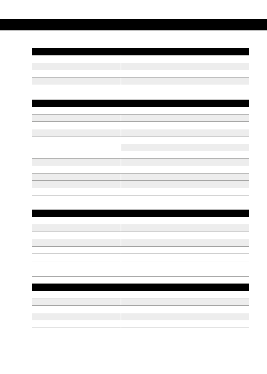
DIMENSIONS
Overall length 2260 mm
Overall width 820 mm
Seat height 970 mm
Wheelbase 1470 mm
Ground clearance 350 mm
MOTOR
Type: Single cylinder 2 stroke liquid cooled
Displacement : 249.32 cc / 293.14 cc
Bore / Stroke 66,4 x 72 mm / 72 x 72 mm
Fuel system Carburator KEIHIN PWK 36
Cooling Liquid system with forcced circulation
Starting System Electric starter
Battery 12 V / 4 Ah
Ignition system DC-CDI no switch with digital advance
Spark plug NGK BR8ES / DENSO W24ESRU
Spark plug gap 0.7 mm
Alternator 220W
Engine oil 750 ml 10 W 40
Technical Specifications
CARBURETOR
Type of carburetor KEIHIN PWK 36S AG
Needle position 4th position from the top / 3th position from the top
Needle jet N8RJ (N84K) / N8RG
Main jet KEA 165 (KEA 115)
Pilot jet KEP 40 (KEA38) / KEP 38
Starter jet 85 (50)
Air screw adjustment 1 1/2 turns
Slide cut N°7
TRANSMISSION
Type 6 speed
Clutch Multi disc clutch in oil bath, hydraulically operated
Primary drive 27 x 75
Gearbox 6 speed
Secondary drive 14 x 49
68
ENGLISH
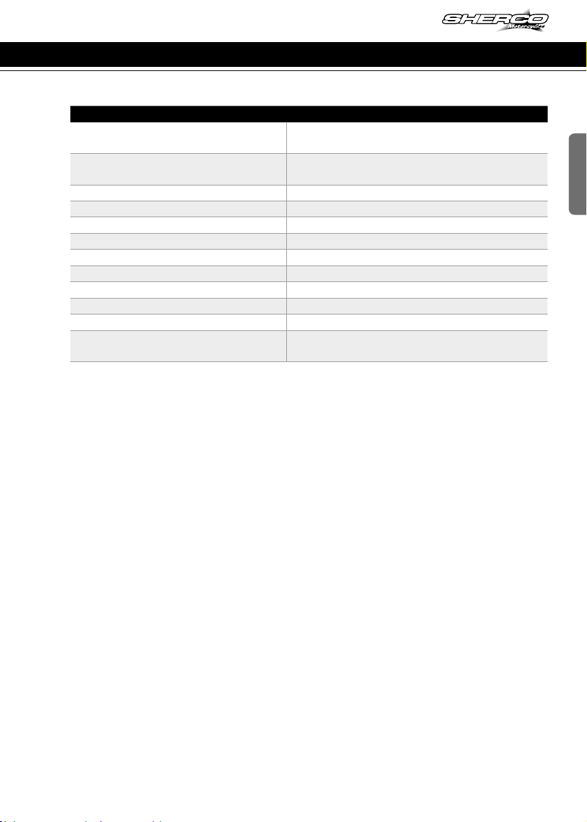
CHASSIS
Frame Semi-perimeter CrMo steel with aluminum sub-
frame
Fork SACHS USD Gold Series 48mm dia. (standard)
WP USD 48mm dia. (racing)
Rear suspension WP Suspension with separate cylinder
Travel front/rear 300/300mm
Front brake disc 270mm (standard), 256mm (racing)
Rear brake disc disque Ø 220mm
Disc brakes wear limit : 2.7mm front and 3.6mm rear
Front tire 90/90-21’’
Rear tire 140/80-18’’
Pressure off-road front / rear 0,9 bar
Fuel tank capacity with reserve 9,5l with 1l of reserve
Fuel requirement Unleaded gasoline with an octane index of at
least 95 mixed with 2 stroke oil (2%)
Technical Specifications
69
250-300 SE/R
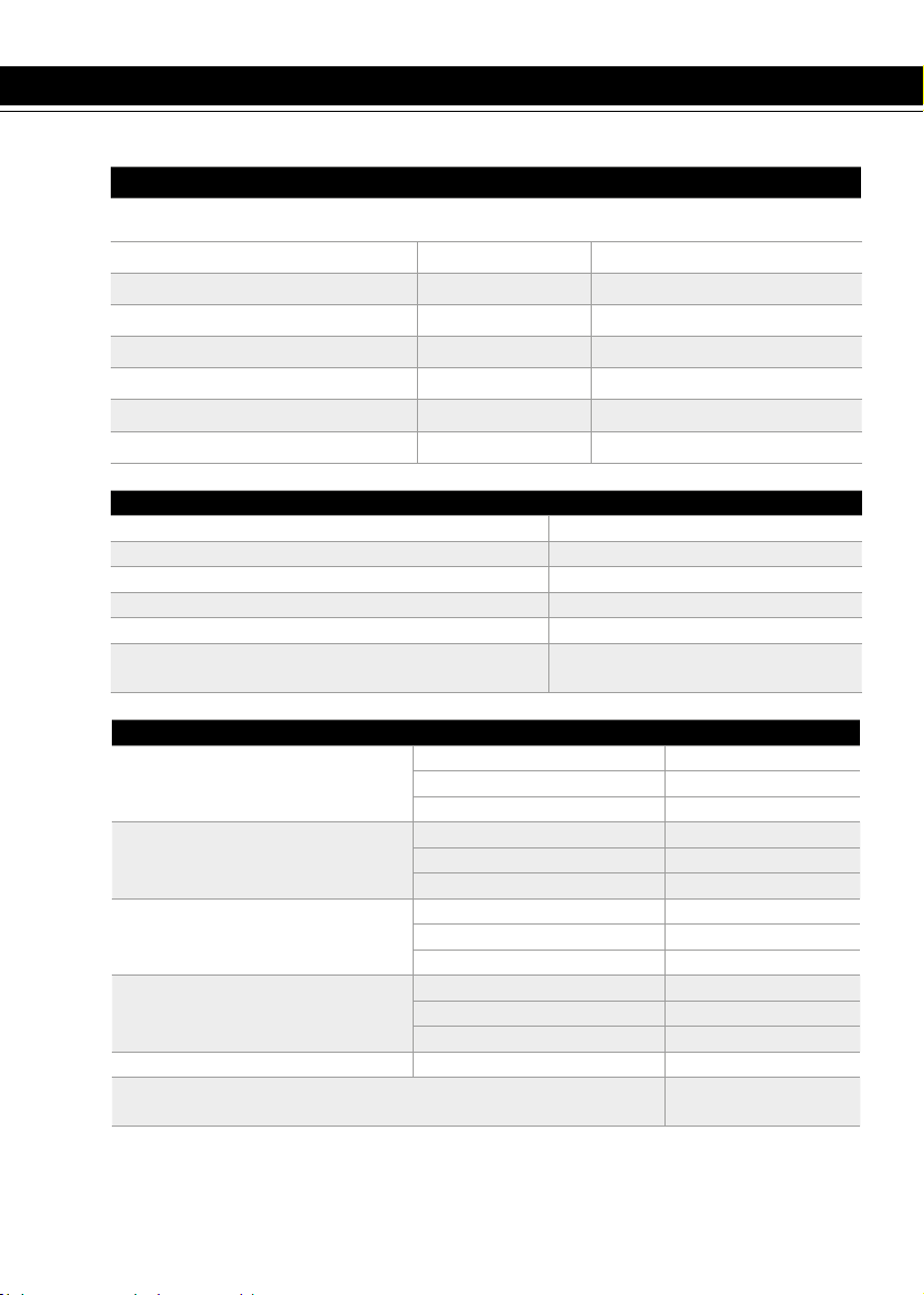
Technical Specifications (continued)
RÉGLAGES - FOURCHE WP SUSPENSION USD Ø48MM
Compression
Comfort 20 clicks back
Standard 13 clicks back
Sport 8 clicks back
Rebound
Comfort 18 clicks back
Standard 13 clicks back
Sport 10 clicks back
Preload
Comfort 4 tours
Standard 6 tours
Sport 8 tours
Spring stiffness
Rider weight : 65-75 kg 4.0N/mm
Rider weight : 75-85kg 4.2N/mm (origine)
Rider weight : 85-95kg 4.4N/mm
Type of oil SAE 4
Oil level measurement (fork compressed and spring removed)
from the top of the fork tube 110mm
Battery Yuasa YTX5 LBS 12V 4Ah
Headlight S2 12V 35/35W
Pilot W5W 12V 5W
Rear tail / stop LED
Flasher R10W 12V 10W
Speedometer battery CR 2032 Battery voltage: 3V
Plate light W5W 12V 5W
ADJUSTMENT – SACHS FRONT FORK USD GOLD SERIES Ø48MM
Compression 12 clicks back
Rebound 12 clicks back
Spring stiffness 4.5N/mm
Type of oil SAE 5
Quantity of oil per fork leg 600cm3
Oil level measurement (fork compressed and
spring removed) from the top of the fork tube
130mm
ELECTRICAL EQUIPMENT
70

ENGLISH
Technical Specifications (continued)
ADJUSTMENT – WP REAR SUSPENSION UNIT
Low-speed compression
Comfort 20 clicks back
Standard 15 clicks back
Sport 12 clicks back
High-speed compression
Comfort 2,5 clicks back
Standard 2 clicks back
Sport 1,5 clicks back
Rebound
Comfort 15 clicks back
Standard 13 clicks back
Sport 11 clicks back
Spring stiffness
Rider weight: : 65-75 kg 48N/mm
Rider weight: : 75-85 kg 51N/mm (original)
Rider weight: : 85-95kg 54N/mm
CLEANING PRODUCTS AND CONSUMABLES
Engine oil SAE J 300
10 W 40 Minerva SAE 10W40
Coolant Minerva Perma Universal
D 4 seasons -25°C
Brake Fluid DOT 4 Minerva brake fluid DOT
4
Fork oil SAE 4
Shock oil SAE2.5
Aerosol chain lube Minerva aerosol chain lub
Air filter cleaner Minerva air filter cleaner
Air filter lubricant Minerva Protect Air
Plastic cleaner Minerva Renovator clea-
ner
Wheel Cleaner Minerva Multi clean Pro
Disc brake Cleaner Minerva brake cleaner
Universal lubricant Minerva F4
71
250-300 SE/R
7 9
2 43 51 6
8
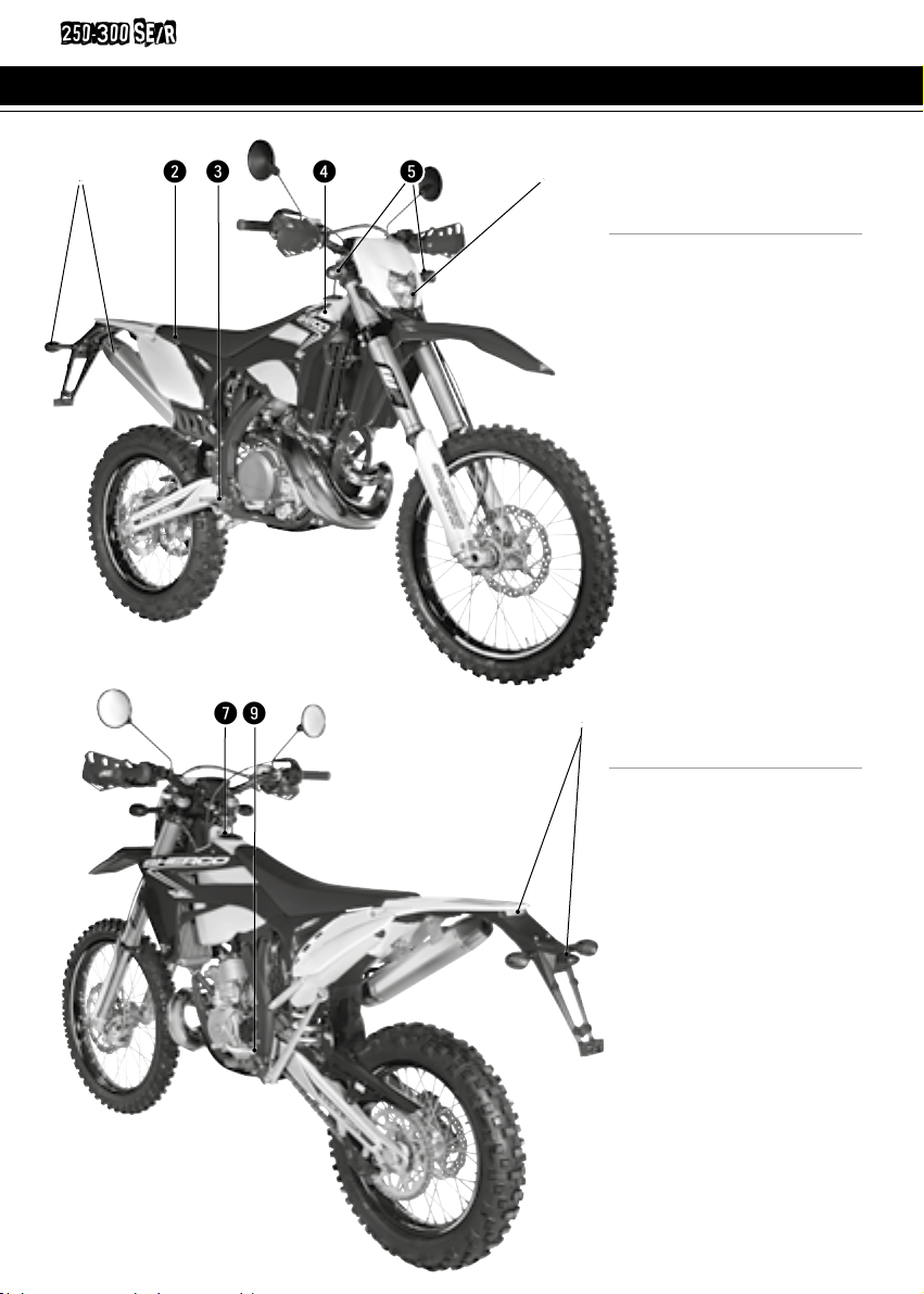
Description of the vehicle
1Clignotants arrière
2Selle
3Pédale de frein arrière
4Réservoir
5Clignotants avant
6Phare
n Right side
1Rear turn signals
2Saddle
3Rear brake pedal
4Fuel tank
5Front turn signals
6Headlight
7Fuel tank cap
8Rear light (tail / brake light /
plate light)
9Gear selector pedal
n Left side
72
q w e tr y u i
2
1
ENGLISH
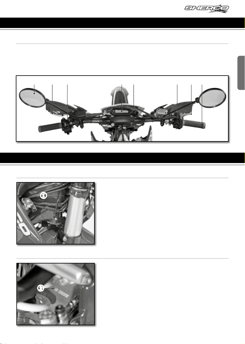
Description of the vehicle (continued)
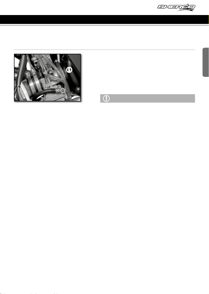
location of the serial numbers
n Engine serial number location
n Vehicle serial number location
qLeft mirror
wClutch lever
eLeft switch
rDashboard
tKey switch
yRight switch
uFront brake lever
iPoignée d’accélérateur
n Controls
2The engine serial number is stamped on the
right side crankcase.
1The serial number of the vehicle is stamped
on the right side of the steering tube.
Engine serial number location
73
250-300 SE/R
1
5
2
3
4
1
A
2
B
1
2
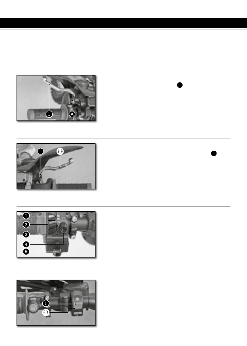
HAND OPERATED CONTROLS:
CLUTCH LEVER, FRONT BRAKE LEVER AND CONTROL SWITCHES
n Left switch (250-300 SE)
1High beam (Headlight)
2Low beam (Headlight)
3Side light (Night))
4Horn
5Flashers
n Light switch on / off (250-300 SE/R)
Two possible positions:
Position ON 1: All lights are on.
Position OFF 2: All lights are off.
n Clutch lever
The clutch lever 1is on the left handlebar and
has an adjustment screw
A
B
n Front brake lever
The front brake lever 2is on the right side of the
handlebar and has an adjustment screw
B
Control devices and controls
74

1
2
1
3
3
1 2
2
ENGLISH
1Starter button
2Injection system mapping selection button
n Rigth switch
The main switch has two positions
Position 1The engine is off and can not be
started.
Position 2The motor can be started.
n Key switch (250-300 SE)
1Dashboard
2Mode selection button
3Key switch (250-300 SE)
n Dashboard (250-300 SE/R)
1Left turn position
2Right turn position
3Off position G and D
n Flasher switch (250-300 SE)
Control devices and controls
75
250-300 SE/R
21
1
2
1
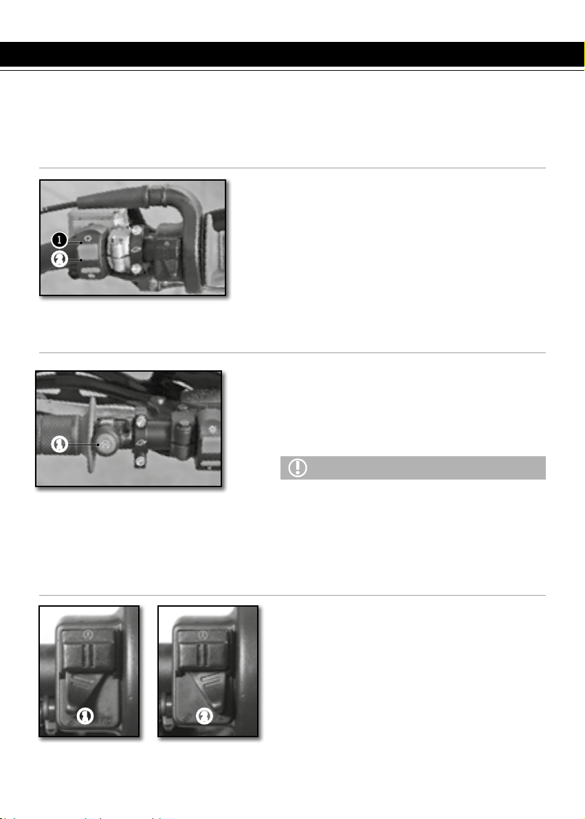
Control devices and controls (continued)
Position 1“Soft”
Position 2“Hard”
n Injection system mapping switch
n Engine on / off switch (250-300 SE/R)
Deux positions possibles :
Position ON 1. Le moteur peut être démarré.
Position OFF 2. Le moteur est coupé et ne peut
pas être démarré.
n Motor emergency stop button (250-300 SE/R)
Two possible positions:
The button is released: in this position, the bike
can be ridden. The button is held down: in this
position the motor is Off when released the
motor can be restarted.
ATTENTION
- If you use the emergency stop button to stop the
motorcycle, do not forget to move the ON / OFF swit-
ch into the OFF position.
- If you do not, there is a risk that the battery will
discharge.-Under normal conditions, use the
ON / OFF switch to stop the bike.
76
1
N
2
3
4
5
6
N
1
1
ENGLISH
Control devices and controls (continued)
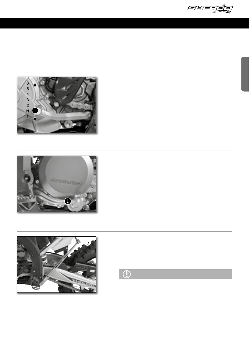
FOOT CONTROLS:
GEAR SELECTOR, SIDE STAND, REAR BRAKE
n Gear selector
The drawing shows the path of the gear selector
for each of the 6 speeds.
n Footbrake
1Rear brake control
n Side stand
Remove the rubber safety latch 1, using your
foot on the shaft unfold it until it supports the
weight of the bike.
ATTENTION
- The stand has a security system which automatically
folds the stand when the bike is moved into an
upright position.
- The stand has been designed to withstand the sheer
weight of the bike.
77
250-300 SE/R
Control devices and controls (continued)
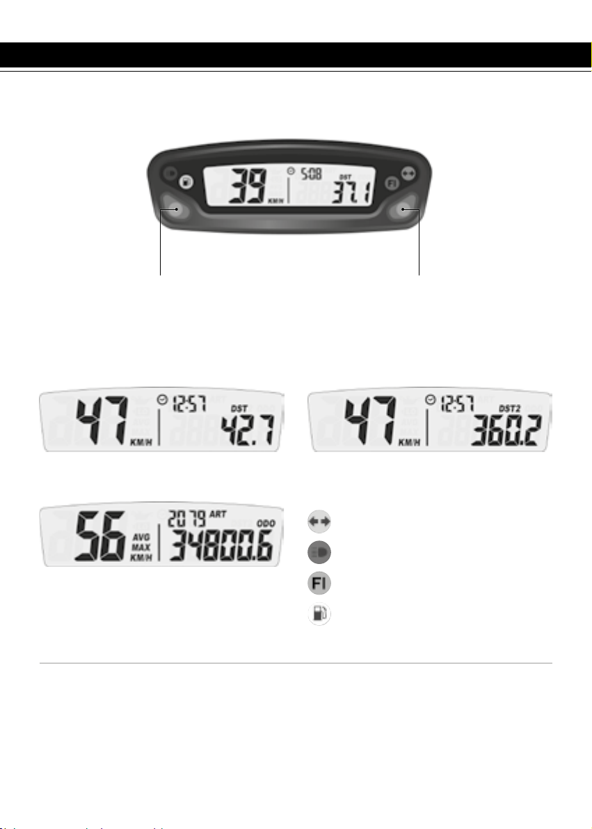
MOTORCYCLE COMPUTER INSTRUCTIONS
Button 1:
Change screens 1,2,3
Hold button 1:
Screen 1: DST Adjust
Screen 2: DST2 Adjust
Button 2:
Change screens 1,2,3
Hold button 2:
Screen 1: Reset DST
Screen 2: Reset DST2
Screen 3: Reset MAX/AVG
Hold buttons 1 et 2:
Setup mode
Screen 1: Speed, Clock, Distance 1 Screen 2: Speed, Clock, Distance 2
Screen 3: Alternating AVG/MAX speed,
Accumulated run time, ODO
n Mode buttons
The vehicle doesn’t need to be switched on
Left button:
Switch between the three display screens
Enter adjustable trip distance mode ( DST
and DST2)
Decrement distance while in adjustable dis-
tance mode
Right button:
Switch between the three display screens
Resets Trip distance 1, Trip distance 2, maxi-
mum and average speed (when pressed and
held for three seconds)
Increments distance while in adjustable dis-
tance mode
Turn indicator
High beam
Fuel injection (MIL): EFI problem
Low fuel
78

ENGLISH
Control devices and controls (continued)
SPD function Current speed (screens 1 and 2):
displays the current speed of the vehicle.
The speed can be displayed in km/h (default)
or mph. (☛p.81)
MAX speed (screen 3): displays the maximum
speed since the last reset was performed.
The maximum speed can be displayed in
km/h (default) or mph. (☛p.81)
Reset to 0 →MAX Function→Hold the right
Button down for 3seconds →0→Reset to 0
done
AVG function Average speed (screen 3): displays
the average speed of the vehicle since the
last reset was performed.
The average speed is displayed in the chosen
units, km/h (default) or mph (☛p.81)
Reset to 0 →AVG Function→Hold the right
Button down for 3seconds →0→Reset to 0
done
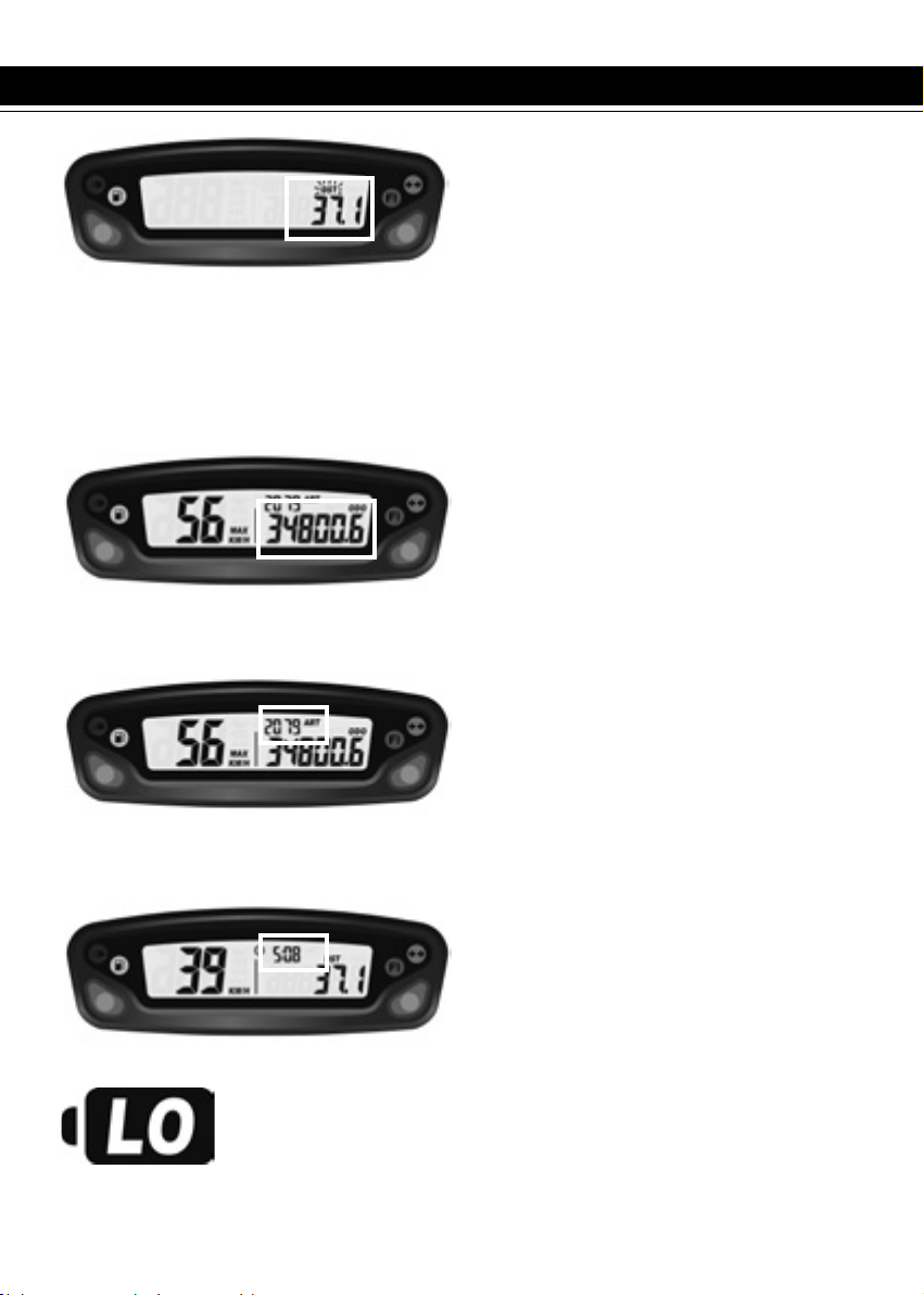
DST function (screen 1): displays the mileage
traveled by the vehicle since the last reset
was performed.
The distance is displayed in the selected
units, km/h (default) or mph (☛p.81)
Reset to 0 →DST Function→Hold the right
Button down for 3seconds →0.0→Reset to 0
done
DST2 function (screen 1): displays the mileage
traveled by the vehicle since the last reset
was performed.
The distance is displayed in the selected
units, km/h (default) or mph (☛p.81)
Reset to 0 →DST2 Function→Hold the right
Button down for 3seconds →0.0→Reset to 0
done
Fig 1 SPD function
Fig 2 MAX speed function
Fig 3 AVG function
Fig 4 DST function
Fig 5 DST2 function
79
250-300 SE/R
DST and DST2 can be incremented or decre-
mented by the user
DST set up (screen 1) →Hold the left Button
down for 3seconds →«DST» icon will flash
→ Hold left Button to decrement/ Hold the
right Button to increment →back to screen 1
DST2 set up (screen 2) →Hold the left Button
down for 3seconds →«DST2» icon will flash
→ Hold left Button to decrement/ Hold the
right Button to increment →back to screen 2
ODO function Odometer (screen 3): displays the
total mileage traveled by the vehicle.
The total distance is displayed in the selected
units, km/h (default) or mph (☛p.17)
This information can not be reset to 0.
Beyond 399 999 km (or miles), the counter
goes back to 0.
ART function Accumulated Ride Time (screen 3):
displays the hours of operation of the vehicle.
This information can not be reset to 0.
Until 99h59min →displayed in one minute
increments
After 99h59min up to 9999h →displayed in
one hour increments
If the unit should reach 9999 hours of accu-
mulated ride time, the display will stop incre-
menting, and will remain at that number.
Clock function (screens 1 et 2): displays clock
information
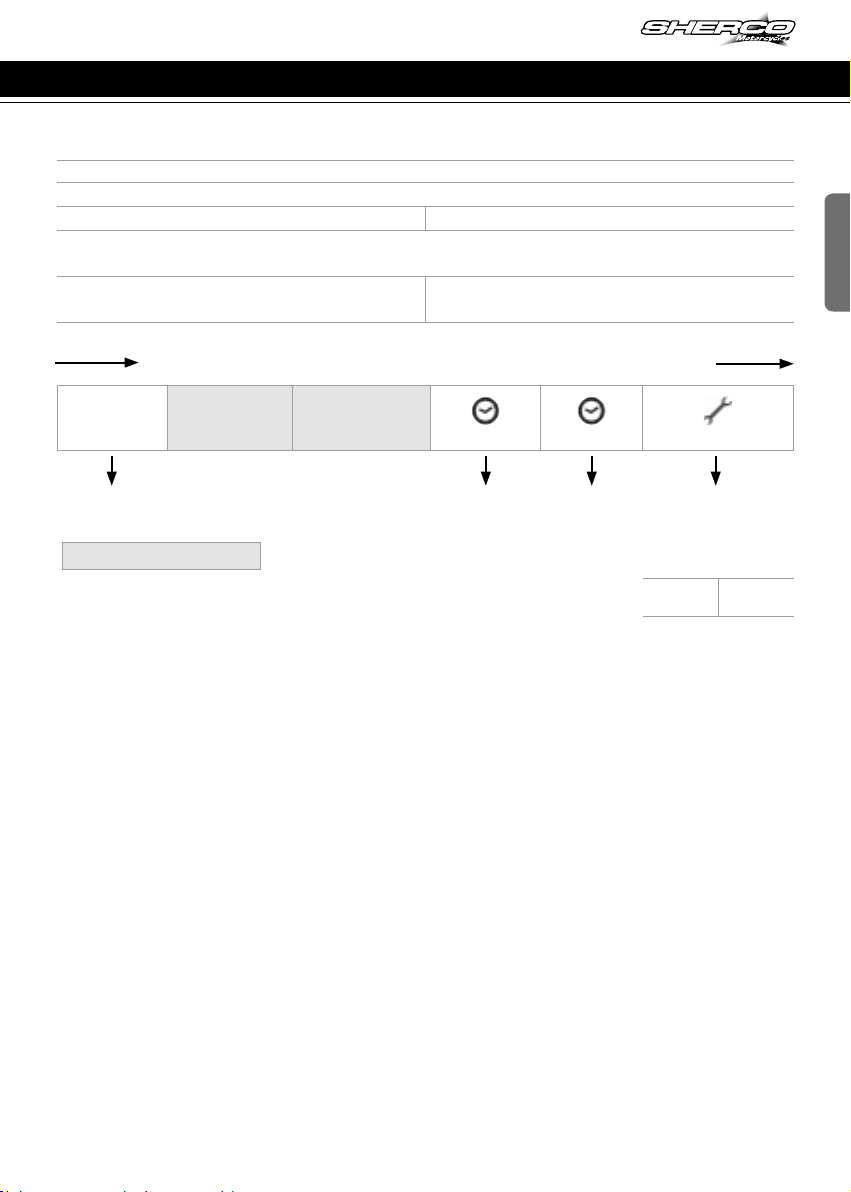
Low battery/ Low battery error function:
->When the battery voltage drops to less than 2.40V, the LO battery
warning will turn on.
->When the internal battery is critically low, the unit will only display a
blinking «LO» icon.
Fig 6 Adjustable trip distance function
Fig 7 ODO function
Fig 8 ART function
Fig 9 Clock function
Fig 11 Low battery/ Low
battery error function
Control devices and controls (continued)
80
ENGLISH
Maintenance reminder: maintenance reminder function is a countdown from a user defined number.
When the maintenance countdown gets to zero, the maintenance icon will appear on the LCD.
Follow these steps to reset or display the remaining accumulated ride time until next service remin-
der:
Displaying the remaining accumulated ride time (screen 3) →Hold the left Button down for 3seconds
→ the remaining value is displayed →no button activation →back to screen 3
Resetting the remaining accumulated ride time (screen 3) →Hold the left Button down for 3seconds →
the remaining value is displayed →Hold the right Button down for 3seconds →The maintenance
reminder is reset to zero (will begin the countdown again according to the maintenance interval
already chosen in the set up menu)
Note:
If the maintenance icon is already on, the distance displayed will be zero
If the maintenance reminder is turned off , the information displayed on the screen will be OFF
n Set up menu
Left and right buttons pressed simultaneously for 3s activates the Set up mode
Left button Right button
Toggle between M/H and KM/H settings
Toggle between 24 Hour et 12 Hour
Decrement time of day value
Decrement maintenance reminder value
Increment time of day value
Increment maintenance reminder value
UNIT
(Unit type)
LIFE
(Wheel circumference)
Do not modify these settings
PPr
(Pulse per revolution)
(Clock format)
(Clock setup)
(Maintenance reminder)
The meter will automatically advance from one setting option
to the next, after 5s of no button activation
Miles or Km
Default: km
12 or 24h
Default: 24h
Clock setup Maintenance reminder
setting ( in hours)
Default setting:
5h (first oil change)
OFF:
disabled
Set the
value
Control devices and controls (continued)
81

250-300 SE/R
1
OPENING AND CLOSING THE FUEL TANK
n Fuel tap
The fuel tap is on the right side of fuel tank.
Tap handle 1on the fuel tap is used to open or
close the supply of fuel to the carburetor.
OFF ➝Fuel cannot flow from the fuel tank to the
carburetor.
ON ➝Fuel can flow from the fuel tank to the
carburetor. The fuel tank empties to the point of
reserve capacity.
RES ➝Fuel can flow from the fuel tank to the
carburetor. The fuel tank empties fully.
n Fuel
Use only unleaded fuel with an octane index of at
least 95 mixed with 2 stroke oil (2%)
n Filler cap
Open : Turn the cap counter clockwise. The
opposite direction to the hands of a watch
Close : Turn the cap clockwise. The same direc-
tion as the hands of a watch
Control devices and controls (continued)
82
1
ENGLISH
n Choke
The choke lever 1is fitted on the left side of the
carburetor.
Choke function activated ➝The choke lever is
pulled out all the way.
Choke function deactivated ➝The choke lever
is pushed in all the way.
ATTENTION
If the engine is warm , the choke function must be
deactivated.
Control devices and controls (continued)
83

250-300 SE/R
Riding the motorcycle
n Cold engine starting
1. Turn the ignition key to start position (right)
2. Make sure the gear selector is in neutral
3. Activate the choke
4. Start the engine by pressing the starter button, with the throttle closed
5. Allow the engine to warm up for few minutes
6. Deactivate the choke
n Hot engine starting
Follow the instructions above without step 3-5 and 6.
n Shifting gears
- The positions of the gear selector are shown on (☛ p.77)
- To find the neutral position, press the selector down into first gear (a resistance will be felt),
then move the selector up slightly.
1. Close the throttle before changing gears.
2. Engage the lowest gear.
3. Partially open the throttle while engaging the clutch.
n Parking
- Stop the engine and remove the ignition key.
Become familiar with all of the controls and their functions before using the vehicle.
84
Table of contents


