Deger Energie DEGERtraker 3000NT User manual
Assembly Instruction
DEGERtraker 3000NT
DEGERtraker 3000HD
DEGERtraker 5000NT
DEGERtraker 5000HD
DEGERtraker 6000NT
DEGERtraker 7000NT
DEGERtraker 9000NT
Effective 2012-07-01

Assembly Instruction
DEGERtraker
List of content
Assembly Instruction DEGERtraker 3000NT / 3000HD / 5000NT / 5000HD / 6000NT / 7000NT / 9000NT
2012-07-01
List of content
Part I Basics
Introduction.........................................................................................................................Page I-1
Security advices................................................................................................................. Page I-2
Short assembly instruction.…………………………..…………………………................…...Page I-3
Scope of delivery................................................................................................................Page I-4
Part II Foundation and mast
Assembly foundation.......................................................................................................... Page II-1
Assembly of the mast......................................................................................................... Page II-3
Dimensions.........................................................................................................................Page II-4
Part III Structure
Assembly integrated motor east-west and boomerang...................................................... Page III-1
Assembly boomerang and limit switch............................................................................... Page III-2
Assembly base frame.........................................................................................................Page III-3
Assembly Elevation-Motor (EMO)...................................................................................... Page III-6
Part IV Module carry system
DEGERtraker 3000NT / 3000HD........................................................................................Page IV-1
DEGERtraker 5000NT / 5000HD........................................................................................Page IV-2
DEGERtraker 6000NT........................................................................................................Page IV-3
DEGERtraker 7000NT........................................................................................................Page IV-4
DEGERtraker 9000NT........................................................................................................Page IV-5
Assembly of aluminium profiles and the modules.............................................................. Page IV-6
Assembly of the modules................................................................................................... Page IV-7
Assembly inverter holding (optional)…………....................................................................Page IV-8
Part V Control unit
Assembly control unit ........................................................................................................ Page V-1
Data sheet energy converter 6........................................................................................... Page V-2
Data sheet Central Control Box II……………………………………………………………... Page V-3
Data sheet Central Control Box III…..………………………………….……………………... Page V-4
Connecting energy converter to Central Control Box.........................................................Page V-5
DEGERcontrolsystem to DEGERtraker……………………………………………………….. Page V-6
CCB and Wind guard, Sunlight Sensor, Security Sensor...................................................Page V-7
Functional characteristics –arrangement check................................................................ Page V-8
Part VI Certificates
Declaration of conformity....................................................................................................Page VI-1
Declaration of commitment.................................................................................................Page VI-2
Report of implementing...................................................................................................... Page VI-3
Part VII Trouble shooting / Maintenace
Trouble shooting.................................................................................................................Page VII-1
Maintenance.......................................................................................................................Page VII-2
Fault report......................................................................................................................... Page VII-3
Please pay attention to the instructions on Page
I-1 and I-2!

Assembly Instruction
DEGERtraker
Part I - Basics
Inroduction
Assembly Instruction DEGERtraker 3000NT / 3000HD / 5000NT / 5000HD / 6000NT / 7000NT / 9000NT
2012-07-01
Page I-1
Congratulation for aquiring a DEGERtraker.
You decided on a high quality dual-axis solar tracking system which is suitable for all current photovoltaic
solar modules.
Maximum solar yield:
The maximum solar yield can be achieved with the DEGERtraker tracking system.
By using the DEGERtraker tracking system, you are truly acknowledging the power of nature: you are not
only protecting our environment and nature but you are increasing your yield and thus achieving ROI sooner.
During the day, the DEGERtraker aligns itself like a sunflower following the sun or the brightest source of
light.
Maintenance-free. Long-life. Recyclable.
The systems designed to these exacting parameters are mass-produced in an ISO 9001-certified factory
under environmentally sound conditions. DEGERtraker systems are truly 99.9% recyclable.
Compared with rigid systems, the amount of electronic scrap after useful life is 40% lower!
Quick installation.
Pre-assembled components with detailed instructions allow an installation within less than four hours (after
the mast has been erected).
A technology to rely on.
The fact that the patent-protected control system and the utility model-protected mechanical system were
awarded the inventor’s prize of the federal state of Baden-Württemberg in South-Germany in 2000 shows
that the DEGERtraker meets the demands of both experts and investors.
Since this award the control unit and the mechanical system have been improved continuously. The design
of the DEGERtrakers is done according to DIN 1055-4 (3/2005) with independent certification.
Scope of delivery.
Complete dual-axis tracking system: mast, rotating head, supporting frame, aluminium solar module carrier
system - to fit the respective module type.
Control electronics: DEGERconecter with energy converter for extremely economical operation, wind monitor
and optional sunlight sensor and security sensor.
Foundation plan and this assembly instructions.
ATTENTION!
Read all of the instructions prior to working with the
equipment and save these Assembly Instructions!
The installation of the DEGERtraker may only be conducted by suitable specialists!
We recommend that the system be inspected by a master electrician, or at least a person with
equivalent qualification, after completion.
A fault report (page VII-3) must be submitted in order to process complaints. Complaints cannot be
processed if fault reports have not been filled out correctly!! (the serial number of the defect system
must be included in the report)
Assembly Instruction
DEGERtraker
Part I - Basics
Security advices
Assembly Instruction DEGERtraker 3000NT / 3000HD / 5000NT / 5000HD / 6000NT / 7000NT / 9000NT
2012-07-01
Page I-2
The installed DEGERtraker tracking system has to be protected against trespassing in its
whole sphere of action by adapted measures, for example by errecting a fence.
While assemblage of the DEGERtraker or parts of the system and while the system is put
into operation some risks of injury exist caused by moveable parts of the tracking system. To protect injuries
caused by possibly existing burrs or sharp angles we imperatively recommend to wear gloves when
mounting the steel parts of the system.
In case of checks or changes at the DEGERtraker all parts of the system have to be free of
potential through a Customer-supplied electrical power switch. Zero-potential and mechanical protection
have to be proven and guaranteed due to the “General rules for accident prevention”. When voltage supply
is indispensable for checking the system injuries of persons have to be ruled out by adapted actions.
Lightning protection and grounding should be installed/designed in accordance with state
specific requirements and national standards for photovoltaic systems.
The whole sphere of action has to be free of any objects.
Elevation-axle and azimuth-axle of the DEGERtraker can be moved manually by the enclosed Central
Control Box (CCB). Therefore please pay attention to part V of this assembly instruction.
To move the traker safely in the horizontal position in case of power failure we recommend
to use a uninterruptible power supply. When all electrical components fail the systems can be moved into the
horizontal position by using standard tools. (see III-6)
The development of the DEGERtrakers is based on the DIN 1055-4. Reducing the module surface the
system will be able to resist higher demands than the values given in the norm. The maximum mountable
module surface depends on regional conditions and regulations. To calculate the maximum mountable
module surface a dimensioning-tool is available on our website. The download of the dimensioning-tool is
free.
DEGERtrakers can also be set up in earthquake endangered zones without reservation in respect
of module area or foundations geometry.
In case of accumulation of snow on the module surface with more than 35kg/m²(equivalent
to about 8 cm wet snow and about 15 cm powder snow) it is necessary to broach the module surface. It is
possible to do this by activating manually the CCB as described above.
For 6000NT and 9000NT the snow sensor is mandatory. Upon failure of the snow sensor, it is necessary to
tilt the module surface at a load of more than 10kg/m².
Intended Use
A DEGERtraker is designed and dimensioned to be applied with standard-photovoltaic
modules and is therefore not adapted to be applied with concentrator modules, mirrors, solar thermal
collectors etc. The maximum mountable module surface calculated by the dimensioning-tool must not be
exceeded in any case. As soon as the modules are mounted an operating wind guard has to be assembled
or the module surface has to stay in the horizontal position.
Permissible ambient temperature: -20°C to +55°C
Sound level Distance 20m: no difference to the sound level of the surrounding measurable
Distance 10m: 40 dB(A) Reference value: 40 dB(A) corresponds to:
- tweet of a bird
- usual background sound level in a house

Assembly Instruction
DEGERtraker
Part I - Basics
Short assembly instruction
Assembly Instruction DEGERtraker 3000NT / 3000HD / 5000NT / 5000HD / 6000NT / 7000NT / 9000NT
2012-07-01
Page I-3
1st step
Assembly of foundation and mast
______________________________________________________________________________________
2nd step
Assembly of integrated motor east west
______________________________________________________________________________________
3rd step
Assembly of base frame
______________________________________________________________________________________
4th step
Assembly of Elevation motor
______________________________________________________________________________________
5th step
Assembly of modules and control unit
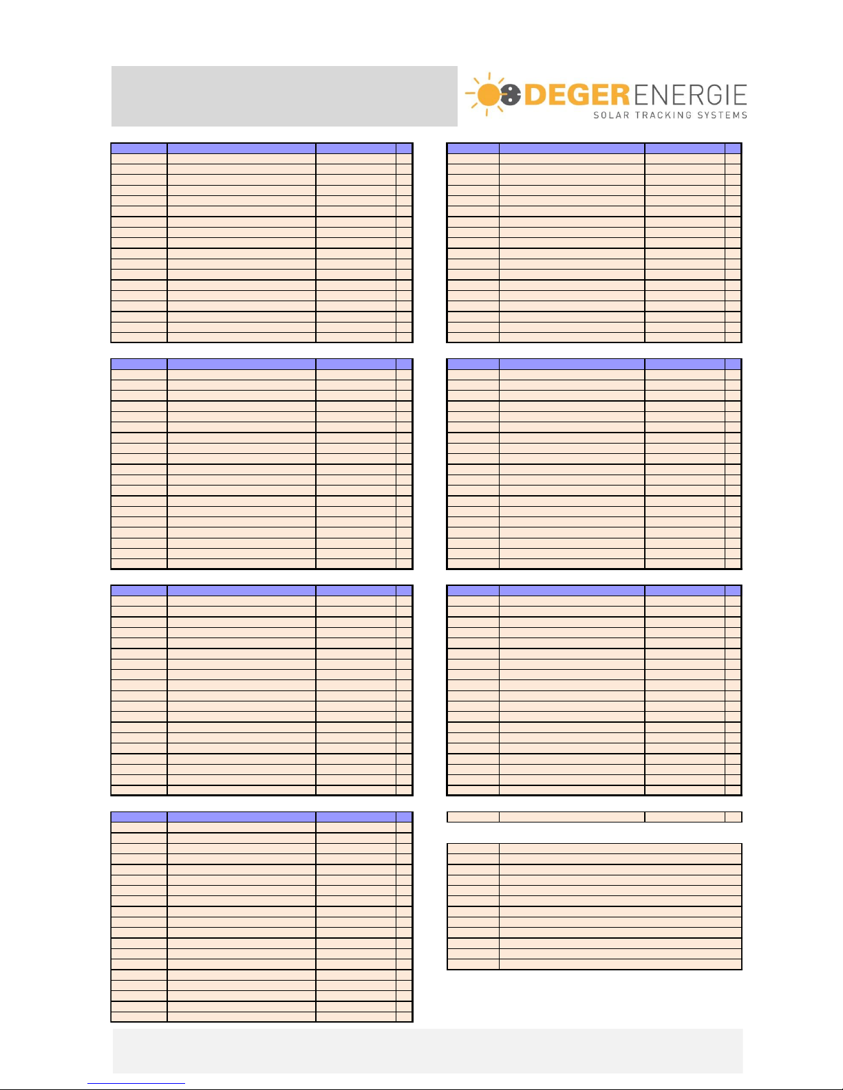
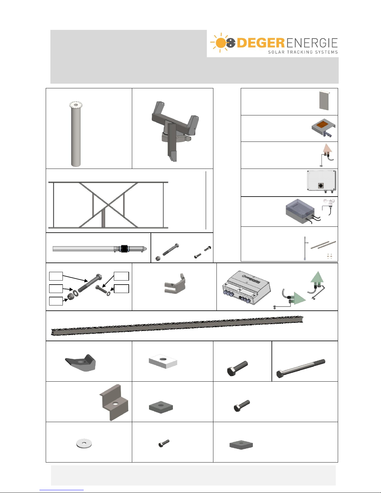
Scope of delivery
DEGERtraker
Assembly Instruction DEGERtraker 3000NT / 3000HD / 5000NT / 5000HD / 6000NT / 7000NT / 9000NT
2012-07-01
Page I-4
A-Nr. Name of item p
Pos.
A-Nr. Name of item p
* Mast 1 1* Mast 1
8100041 Rotating head 3000NT 1 28100048 Rotating head 3000HD 1
8100017 Base frame 3000NT 1 38100018 Base frame 3000HD 1
4100038 Elevation-motor EMO V 1 44100038 Elevation-motor EMO V 1
8100036 Boltpack rotating head 1 58100019 Boltpack rotating head 1
6800003 Tread locking fluid 5g 1 66800003 Tread locking fluid 5g 1
8100034 Boomerang II3000NT 1 78100031 Boomerang II3000HD 1
8910 Assembly instruction 1 88910 Assembly instruction 1
8100115 Energy converter 6 1 98100115 Energy converter 6 1
* Aluminiumprofiles F-Set-HD * 10 * Aluminiumprofiles F-Set-HD *
6900003 Sliding nut M10, 30x20x6
Alu/Base frame
*12 6900003 Sliding nut M10, 30x20x6
Alu/Base frame
*
6100005 Bolt M10x140
Alu/Base
*14 6100005 Bolt M10x140
Alu/Base
*
* End clamp Solar module * 15 * End clamp Solar module *
6900007 Sliding nut M8 20x20x5 Solar module * 16 6900007 Sliding nut M8 20x20x5 Solar module *
* Bolt M8 Solar module * 17 * Bolt M8 Solar module *
6900015 Clamp plate 25x6, 4x2 Solar module * 18 6900015 Clamp plate 25x6, 4x2 Solar module *
* Bolt M6 Solar module * 19 * Bolt M6 Solar module *
6900006 Sliding nut M6 20x20x5 Solar module * 20 6900006 Sliding nut M6 20x20x5 Solar module *
A-Nr. Name of item p
Pos.
A-Nr. Name of item pc
* Mast 1 1* Mast 1
8100005 Rotating head 5000NT 1 28100046 Rotating head 5000HD 1
8100003 Base frame 5000NT 1 38100027 Base frame 5000HD 1
4100038 Elevation-motor EMO V 1 44100055 Elevation-motor EMO 1
8100036 Boltpack rotating head 1 58100019 Boltpack rotating head 1
6800003 Tread locking fluid 5g 1 66800003 Tread locking fluid 5g 1
8100034 Boomerang II5000NT 1 78100032 Boomerang II5000HD 1
8910 Assembly instruction 1 88910 Assembly instruction 1
8100115 Energy converter 6 1 98100115 Energy converter 6 1
* Aluminiumprofiles F-Set-X * 10 * Aluminiumprofiles F-Set-HD *
6900011
Clamp MTHM10-vz. Nova-Grip
Alu/Base frame
*11 6900011
Clamp MTHM10-vz. Nova-Grip
Alu/Base frame
*
6900003 Sliding nut M10, 30x20x6
Alu/Base frame
*12 6900003 Sliding nut M10, 30x20x6
Alu/Base frame
*
6100020 Bolt M10x35
Alu/Base frame
*13 6100020 Bolt M10x35
Alu/Base frame
*
* End clamp Solar module * 15 * End clamp Solar module *
6900007 Sliding nut M8 20x20x5 Solar module * 16 6900007 Sliding nut M8 20x20x5 Solar module *
* Bolt M8 Solar module * 17 * Bolt M8 Solar module *
6900015 Clamp plate 25x6, 4x2 Solar module * 18 6900015 Clamp plate 25x6, 4x2 Solar module *
* Bolt M6 Solar module * 19 * Bolt M6 Solar module *
6900006 Sliding nut M6 20x20x5 Solar module * 20 6900006 Sliding nut M6 20x20x5 Solar module *
A-Nr. Name of item p
Pos.
A-Nr. Name of item p
* Mast 1 1* Mast 1
8100083 Rotating head 6000NT 1 28100006 Rotating head 7000NT 1
8100081 Base frame 6000NT 1 38100004 Base frame 7000NT 1
4100055 Elevation-motor EMO V HD 1 44100038 Elevation-motor EMO V 1
8100019 Boltpack rotating head 1 58100019 Boltpack rotating head 1
6800003 Tread locking fluid 5g 1 66800003 Tread locking fluid 5g 1
8100032 Boomerang II6000NT 1 78100031 Boomerang II7000NT 1
8910 Assembly instruction 1 88910 Assembly instruction 1
8100115 Energy converter 6 1 98100115 Energy converter 6 1
* Aluminiumprofiles F-Set-HD * 10 * Aluminiumprofiles F-Set-X *
6900011
Clamp MTHM10-vz. Nova-Grip
Alu/Base frame
*11 6900011
Clamp MTHM10-vz. Nova-Grip
Alu/Base frame
*
6900003 Sliding nut M10, 30x20x6
Alu/Base frame
*12 6900003 Sliding nut M10, 30x20x6
Alu/Base frame
*
6100020 Bolt M10x35
Alu/Base frame
*13 6100020 Bolt M10x35
Alu/Base frame
*
* End clamp Solar module * 15 * End clamp Solar module *
6900007 Sliding nut M8 20x20x5 Solar module * 16 6900007 Sliding nut M8 20x20x5 Solar module *
* Bolt M8 Solar module * 17 * Bolt M8 Solar module *
6900015 Clamp plate 25x6, 4x2 Solar module * 18 6900015 Clamp plate 25x6, 4x2 Solar module *
* Bolt M6 Solar module * 19 * Bolt M6 Solar module *
6900006 Sliding nut M6 20x20x5 Solar module * 20 6900006 Sliding nut M6 20x20x5 Solar module *
Pos. 4a:
A-Nr. Name of item p 4100064 Boltpack EMO 1
* Mast 1
8100077 Rotating head 9000NT 1 Optional :
8100074 Base frame 9000NT 1 1900003 Inverter holding plate 1200 mm
4100055 Elevation-motor EMO HD 1 1900004 Inverter holding plate 900 mm
8100019 Boltpack rotating head 1 1900005 Inverter holding plate 600 mm
6800003 Tread locking fluid 5g 1 1900010 Inverter holding plate1200mmwithsupport bracket
8100032 Boomerang II9000NT 1 1900011 Inverter holding plate 900mmwithsupport bracket
8910 Assembly instruction 1 1900012
Inverter holding plate 600mmwithsupport bracket
8100115 Energy converter 6 1 1900007 Snow sensor
* Aluminiumprofiles F-Set-HD * 5100032 Sunlight sensor
6900011
Clamp MTHM10-vz. Nova-Grip
Alu/Base frame
*1990001 CentralControlBox BASIC
6900003 Sliding nut M10, 30x20x6
Alu/Base frame
*1990004
6100020 Bolt M10x35
Alu/Base frame
*1990003
* End clamp Solar module * 1990008
6900007 Sliding nut M8 20x20x5 Solar module *
* Bolt M8 Solar module *
6900015 Clamp plate 25x6, 4x2 Solar module * * depending on amount and size of modules
* Bolt M6 Solar module * Theexcat number and dimensionsrefer to theenclosed packing list.
6900006 Sliding nut M6 20x20x5 Solar module *
Inthe packing list you also canfind thecorresponding itemnumber.
1700001 DEGERtraker 7000NT
1300001 DEGERtraker 3000NT
1310001 DEGERtraker 3000HD
1500001 DEGERtraker 5000NT
1510001 DEGERtraker 5000HD
1600001 DEGERtraker 6000NT
1900001 DEGERtraker 9000NT
CentralControlBox STANDARD
CentralControlBox ADVANCED
Pendulumkit for wind guard
Assembly Instruction
DEGERtraker
Part I - Basics
Scope of delivery
Assembly Instruction DEGERtraker 3000NT / 3000HD / 5000NT / 5000HD / 6000NT / 7000NT / 9000NT
2012-07-01
Page I-5
Pos.1 : Mast Pos.2 : Rotating head optional: Inverter holding plate
Snow Sensor
Sunlight Sensor
Pos.3 : Base frame CentralControlBox
for 9000NT
additional:
Wind guard
2x Thread rod BASIC
STANDARD
ADVANCED
Pendulum for Wind guard
Pos.4 :Elevation motor EMO Pos.4a: Bolt pack EMO
Pos. 5 : Bolt pack rotating head Pos. 7 Boomerang II Pos. 9 : Energy converter 6
Pos. 10 : Aluminum profiles
Pos. 11: Clamp MTH M10 Pos 12: Sliding nut M10 Pos. 13: Bolt Pos. 14: Bolt
M10x35 M10x140
Pos. 15: End Clamp Pos. 16: Sliding nut M8 Pos. 17: Bolt M8
Pos. 18: Clamp plate Pos. 19: Bolt M6 Pos. 20: Sliding nut M6
2x
4x
18x
18x
2x
Assembly Instruction
DEGERtraker
Part II –Foundation and mast
Assembley foundation
Assembly Instruction DEGERtraker 3000NT / 3000HD / 5000NT / 5000HD / 6000NT / 7000NT / 9000NT
2012-07-01
Page II-1
A qualified professional must be commissioned with creating the foundation.
We recommend having the foundation reinforcement approved by a qualified engineer or technician
before concreting.
The necessary bearing capacity of the subsoil is 200 kN/m². This value must be checked for
correctness and documented by the site manager in charge. A substratum expert is to be called in if
there is any uncertainty.
In regions and with soils at risk of frost, further measures must be taken to ensure frost protection,
e.g. frost-proof sub-base or lean-mixed concrete fill down to the frost line.
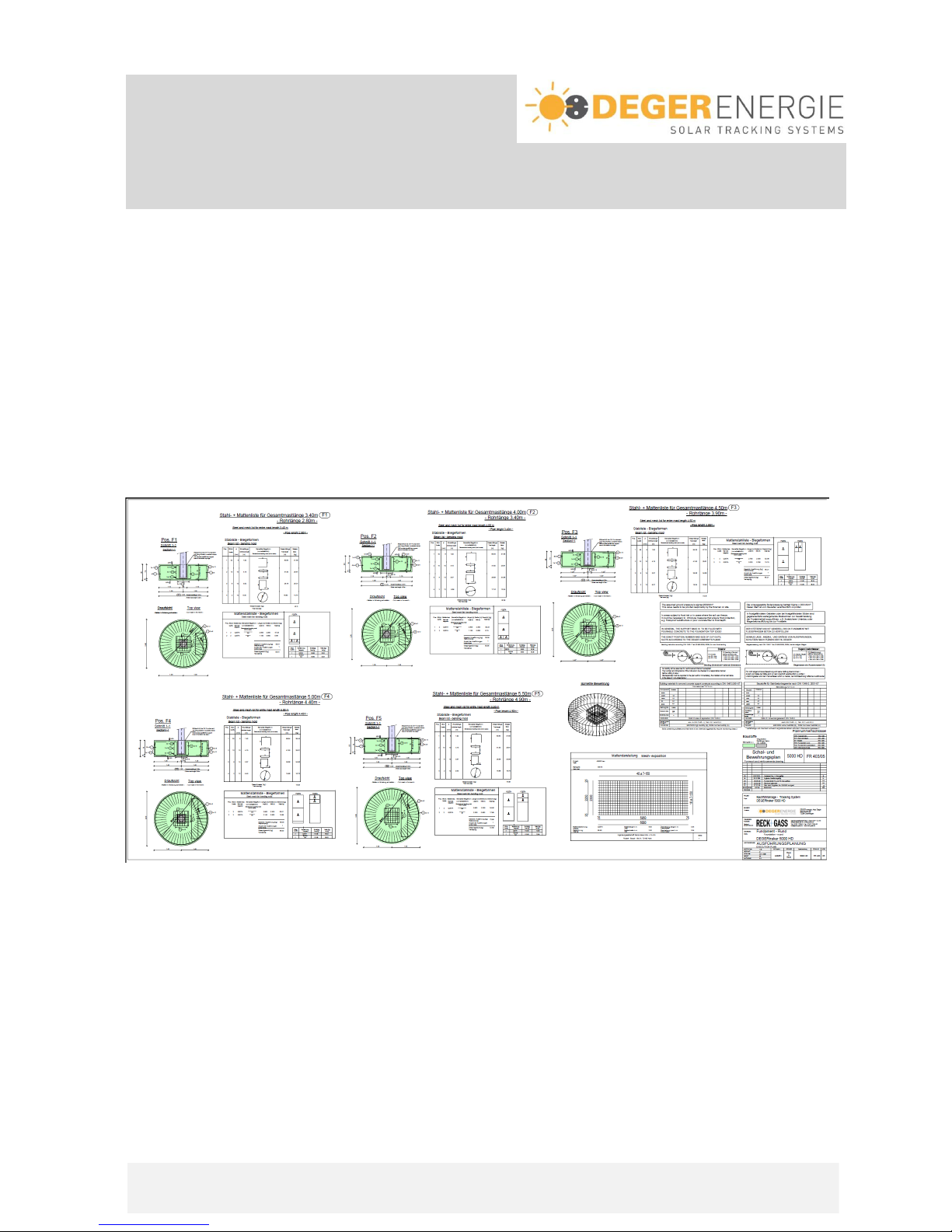
A formwork and reinforcement diagram for the particular foundation, as shown below, can be obtained for
each DEGERtraker on request –you must observe the instructions given in the diagrams! This diagram will
be sent with the order confirmation. The diagram shown is only intended as a sample drawing.
Creating foundation
1st Step:
- Excavate top soil
- Insert conduit for cable (not in picture)
- Install formwork (Foundation dimensions, see page II-4)
- Lay bottom layer of wire-mesh steel Q257A Item1 into the formwork (cut into the formwork)
- Insert a spacer to ensure minimum concrete coverage (5 cm).
Assembly Instruction
DEGERtraker
Part II –Foundation and mast
Assembley foundation
Assembly Instruction DEGERtraker 3000NT / 3000HD / 5000NT / 5000HD / 6000NT / 7000NT / 9000NT
2012-07-01
Page II-2
2nd Step:
- Insert mast mount centrally (height approx.10 cm).
- Install bent bar-steel into the center of the foundation.
ATTENTION: Conduit must be inside the mast
- Install bent bar-steel.
- Install top layer of wire-mesh steel Q257A (cut into the formwork).
3th Step:
- Create formwork for the receiving part.
- Attach foundation formwork.
- Affix foundation formwork in such a way that the formwork pressure generated by filling can be
absorbed.
- Pour out and compact the foundation (without receiving part) using C20/30 concrete.
4th Step:
- Affix mast with 2 reinforcement against rotation.
- Insert mast into the foundation receiving part.
You do not have to take account of the
location of the bores in the flange.
ATTENTION: Conduit must be inside the mast until min.
10 cm above foundation top edge
- Align mast vertically.
- Fill up receiving part and mast base up to the top edge
of the foundation using grout concrete C25/30 (flowable)
and compact the concrete.
The concrete should be allowed to harden for at least 2 days before any further installation work is
done!
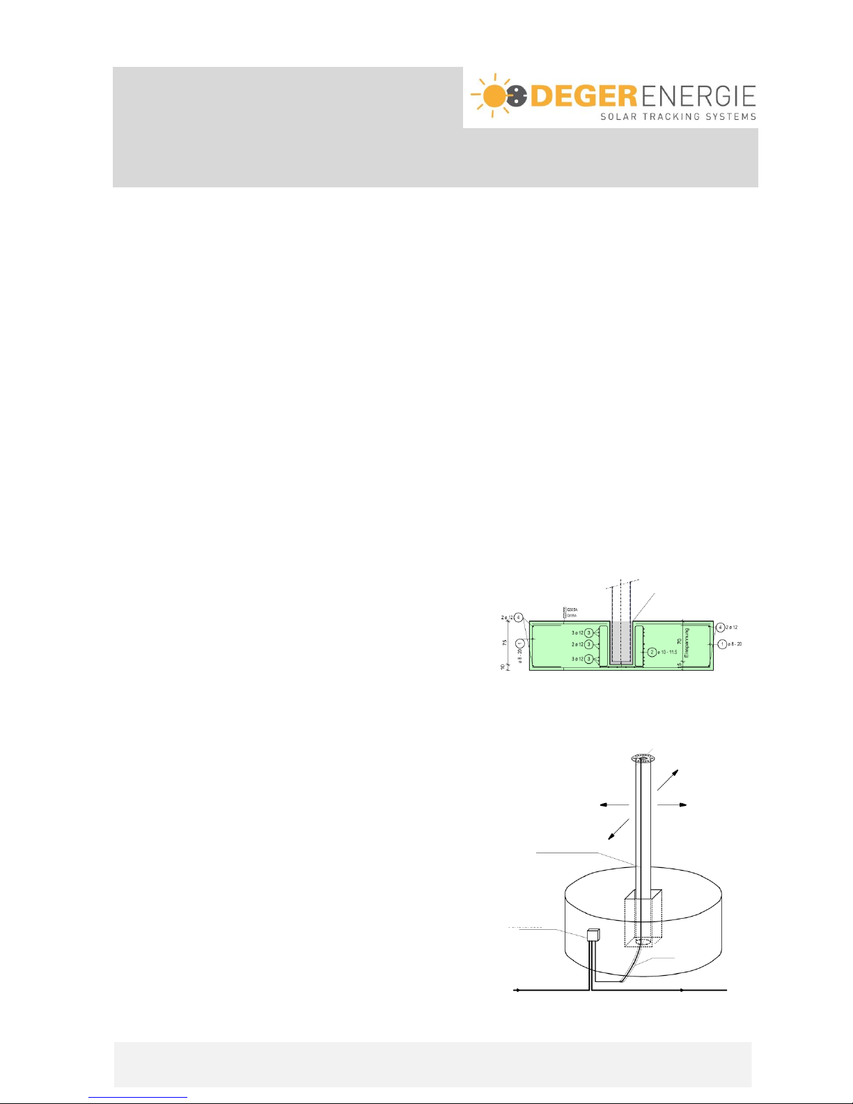
ATTENTION! Cable guide
We recommend you attach a junction box to the side of
the foundations, as shown in the adjacent drawing. The
cables from the junction box to the rotating head must be
designed as flexible rubber cables.
Conduit
Junction box
Flexible
rubber cables
Use concrete backfill
from mast base to
foundation top edge

Assembly Instruction
DEGERtraker
Part II –Foundation and mast
Assembly of the mast
Assembly Instruction DEGERtraker 3000NT / 3000HD / 5000NT / 5000HD / 6000NT / 7000NT / 9000NT
2012-07-01
Page II-3
Example for mounting on concrete wall C20/25:
Dimensions:
Free standing tracker: Tracker building integrated:
ATTENTION!
It is necessary to dimension the mounting for
every system separately according to the
conditions on site.
The calculations are to be assigned to a local
structural engineer who is responsible for the
present building!
Assembly Instruction
DEGERtraker
Part II –Foundation and mast
Dimensions
Assembly Instruction DEGERtraker 3000NT / 3000HD / 5000NT / 5000HD / 6000NT / 7000NT / 9000NT
2012-07-01
Page II-4
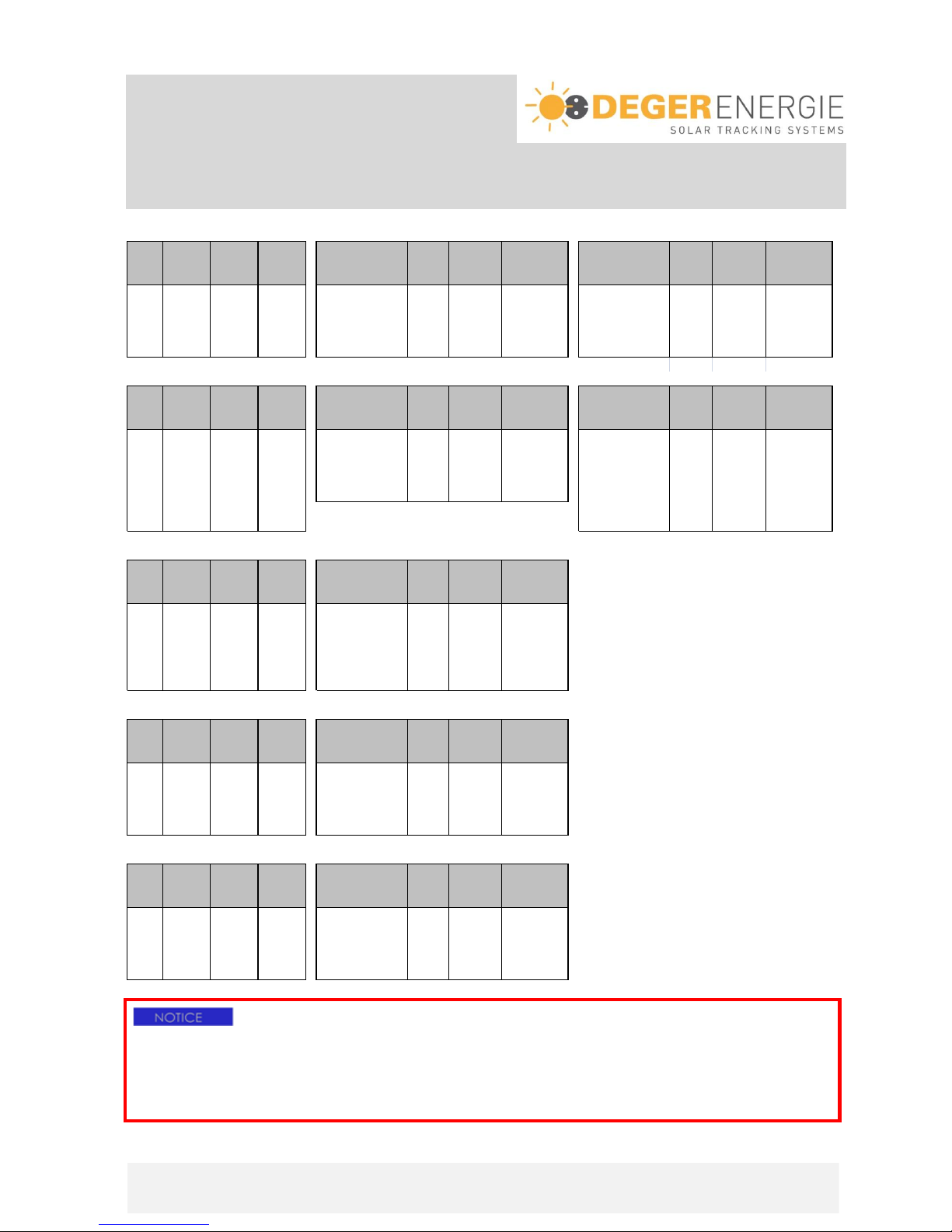
modul
total length
free length
length of mast cross section mast foundation foundation mast cross section mast foundation foundation
area
of the mast
of the mast
restraint Ø / w all thickness weight dimensions dimensions Ø / w all thickness weight dimensions dimensions
m² m m mmm kg cm cm mm kg cm cm
25 3,3 2,6 0,7 tube 219.1 x 7.1 113 Ø205x85 180x180x85 tube 323.9 x 8.8 212 Ø205x85 180x180x85
25 4,0 3,3 0,7 tube 219.1 x 8.0 160 Ø210x85 185x185x85 tube 323.9 x 8.8 263 Ø215x85 190x190x85
25 4,5 3,8 0,7 tube 219.1 x 8.8 198 Ø215x85 190x190x85 tube 323.9 x 8.8 299 Ø225x85 200x200x85
25 5,0 4,3 0,7 tube 219.1 x 10.0 251 Ø225x85 200x200x85 tube 323.9 x 8.8 316 Ø225x85 200x200x85
25 5,5 4,8 0,7 tube 219.1 x 11.0 303 Ø235x85 205x205x85 tube 323.9 x 8.8 350 Ø235x85 200x200x85
modul
total length
free length
length of mast cross section mast foundation foundation mast cross section mast foundation foundation
area
of the mast
of the mast
restraint Ø / w all thickness weight dimensions dimensions Ø / w all thickness weight dimensions dimensions
m² m m mmm kg cm cm mm kg cm cm
40 3,3 2,6 0,7 tube 219.1 x 7.1 113 Ø230x85 200x200x85 tube 323.9 x 8.8 212 Ø260x85 230x230x85
40 4,0 3,3 0,7 tube 219.1 x 8.0 160 Ø250x85 220x220x85 tube 323.9 x 8.8 263 Ø270x85 240x240x85
40 4,5 3,8 0,7 tube 219.1 x 8.8 198 Ø280x85 240x240x85 tube 323.9 x 8.8 299 Ø285x85 250x250x85
40 5,0 4,3 0,7 tube 219.1 x 10.0 251 Ø300x85 260x260x85 tube 323.9 x 8.8 316 Ø290x85 255x255x85
40 5,5 4,8 0,7 tube 219.1 x 11.0 303 Ø310x85 270x270x85 tube 323.9 x 8.8 350 Ø300x85 265x265x85
40 6,0 5,3 0,7 tube 323.9 x 10,0 434 Ø310x85 275x275x85
40 8,0 7,3 0,7 tube 323.9 x 17,5 989 Ø340x85 300x300x85
modul
total length
free length
length of mast cross section mast foundation foundation
area
of the mast
of the mast
restraint Ø / w all thickness weight dimensions dimensions
m² m m mmm kg cm cm
53 4,0 3,3 0,7 tube 323.9 x 7,1 205 Ø255x85 225x225x85
53 4,5 3,8 0,7 tube 323.9 x 7,1 233 Ø260x85 230x230x85
53 5,0 4,3 0,7 tube 323.9 x 8.0 292 Ø265x85 235x235x85
53 5,5 4,8 0,7 tube 323.9 x 8.8 356 Ø270x85 240x240x85
53 6,0 5,3 0,7 tube 323.9 x 8.8 387 Ø285x85 250x250x85
53 8,0 7,3 0,7 tube 323.9 x 14,2 817 Ø310x85 270x270x85
modul
total length
free length
length of mast cross section mast foundation foundation
area
of the mast
of the mast
restraint Ø / w all thickness weight dimensions dimensions
m² m m mmm kg cm cm
60 3,3 2,6 0,7 tube 323.9 x 7.1 166 Ø280x85 280x280x85
60 4,0 3,3 0,7 tube 323.9 x 7.1 205 Ø290x85 290x290x85
60 4,5 3,8 0,7 tube 323.9 x 8.0 259 Ø300x85 300x300x85
60 5,0 4,3 0,7 tube 323.9 x 10.0 356 Ø320x85 320x320x85
60 5,5 4,8 0,7 tube 323.9 x 11.0 430 Ø330x85 330x330x85
modul
total length
free length
length of mast cross section mast foundation foundation
area
of the mast
of the mast
restraint Ø / w all thickness weight dimensions dimensions
m² m m mmm kg cm cm
70 4,0 3,3 0,7 tube 323.9 x 7.1 205 Ø320x85 290x290x85
70 4,5 3,8 0,7 tube 323.9 x 8.0 259 Ø330x85 300x300x85
70 5,0 4,3 0,7 tube 323.9 x 10.0 356 Ø340x85 320x320x85
70 6,0 5,3 0,7 tube 323.9 x 16,0 672 Ø380x85 330x330x85
70 8,0 7,3 0,7 tube 323.9 x 20.0 1121 Ø420x85 365x365x85
NT
NT
DEGERtraker 6000
DEGERtraker 7000
DEGERtraker 9000
NT
HD
NT
HD
NT
DEGERtraker 3000
DEGERtraker 5000
ATTENTION!
The measurements and dimensions listed have been calculated according to DIN norms and should be
understood as a guide values. National norms, directives and materials must also be taken into
consideration. Special foundation plans (also for Canada and USA) can be made available on request!!
The total length of the mast 6,0m and 8,0m are only available in Europe!
Assembly Instruction
DEGERtraker
Part III - Structure
Assembly integrated motor east-west and boomerang
Assembly Instruction DEGERtraker 3000NT / 3000HD / 5000NT / 5000HD / 6000NT / 7000NT / 9000NT
2012-07-01
Page III-1
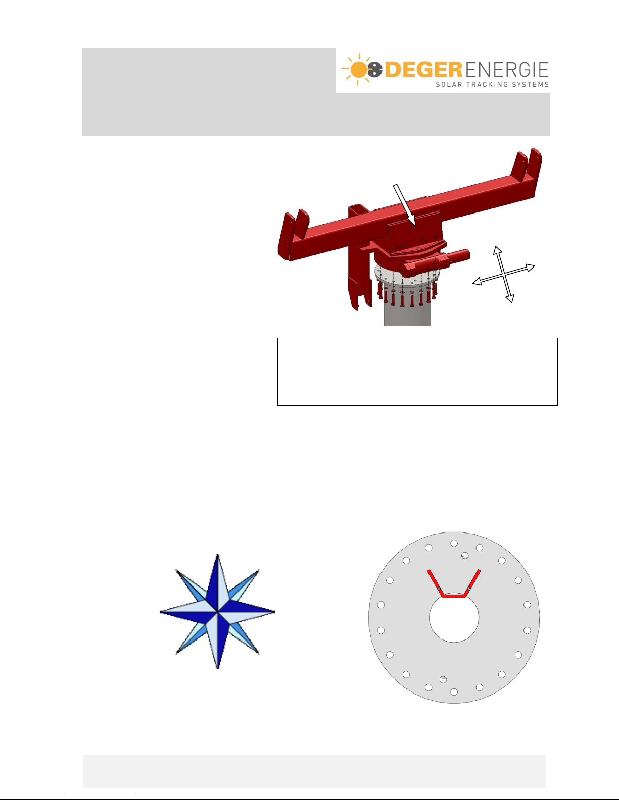
1st step:
Set rotating head carefully onto the flange southward
on the top of the mast. The gearbox should
not get hard knocks.
The drive unit should roughly point south
(+/- 30°) while being screwed tight.
2nd step:
Screw rotating head with the flange by
using bolts M16x75 and washers M16.
torque 200Nm
3rd step:
Mounting boomerang at the mast flange.
The tip of the “boomerang” must point in a southward direction (+/-3°). Use a GPS device or refer to the
surveyor’s plan of the property to determine the south position. A compass is not precise enough.
As the boomerang is operating the end-limit-switch and with this the final position of the east-west-axis is set,
an exact arrangement is necessary.
The position of the bore holes is irrelevant.
Weight of rotation head
DEGERtraker 3000NT, 5000NT 160kg
DEGERtraker 3000HD, 7000NT 240kg
DEGERtraker 5000HD, 6000NT, 9000NT 260kg
N
W
S
O
N
S
O
W

Assembly Instruction
DEGERtraker
Part III –Structure
Assembly boomerang and limit switch
Assembly Instruction DEGERtraker 3000NT / 3000HD / 5000NT / 5000HD / 6000NT / 7000NT / 9000NT
2012-07-01
Page III-2
Push the boomerang as shown at the mast flange and fix it with the screws M5x18.
torque 6.5Nm
4th Step:
Attach the limit switch setting azimuth in the free bore on the rotating head.
Make sure that the switch flag terminals make contact upon operation of the boomerang and that the rotation
movement is stopped.
Assembly instruction
DEGERtraker
Part III –Structure
Assembly base frame
Assembly Instruction DEGERtraker 3000NT / 3000HD / 5000NT / 5000HD / 6000NT / 7000NT / 9000NT
2012-07-01
Page III-3
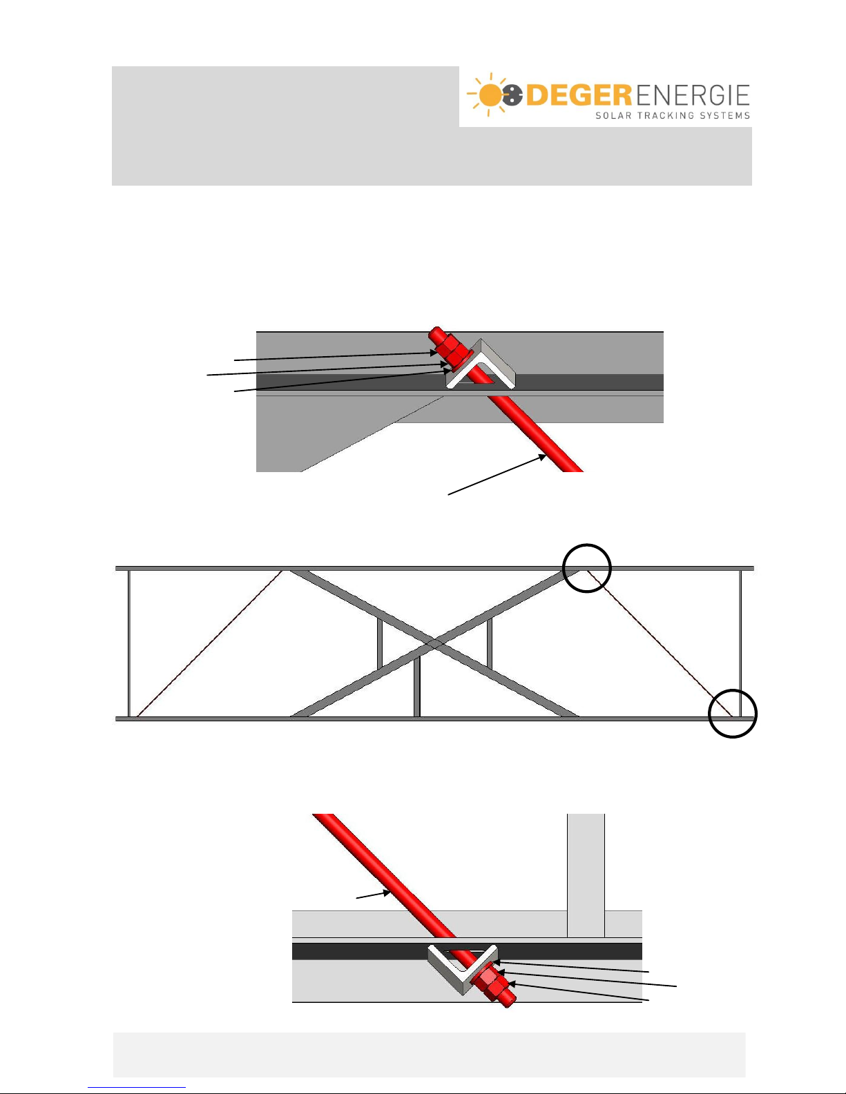
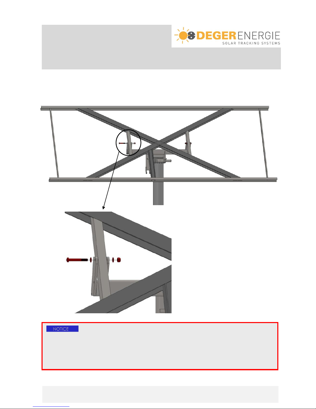
Only required for the DEGERtrakers 9000NT supporting frames:
The tension rods supplied must be installed before assembling the DEGERtrakers 9000NT base frame onto
the rotating head. To do this, push the tension rods through the longitudinal holes of the upper and lower
cross member and secure each with an Washer M12, an M12 nut and an M12 self-locking nut.
torque 15Nm
Detailed view from above:
(sectional view)
Lock nut M12
Nut M12
Washer M12
Tension rod with M12 thread on both sides
top
bottom
Detailed view from below:
(sectional view)
Tension rod with M12 thread on both sides
Washer M12
Nut M12
Lock nut M12

Assembly Instruction
DEGERtraker
Part III –Structure
Assembly base frame
Assembly Instruction DEGERtraker 3000NT / 3000HD / 5000NT / 5000HD / 6000NT / 7000NT / 9000NT
2012-07-01
Page III-4
Before installing the base frame, it is advisable to mark the positions of the aluminium profiles on the side of
the top cross brace and the bottom cross brace –according to the description Part IV.
Labelling must always be from the centre of the cross brace to the outside.
1st step:
Suspend the base frame by using a crane in such a way that the bore holes at the tip of rotation of the base
frame are at the top and the connection for the Elevation motor (EMO) is on the left.
5000NT / 5000HD / 6000NT / 7000NT / 9000NT:
3000NT / 3000HD:
Weight of base frame
DEGERtraker 3000NT 217 kg
DEGERtraker 3000HD 328 kg
DEGERtraker 5000NT 383 kg
DEGERtraker 5000HD 600 kg
DEGERtraker 6000NT 650 kg
DEGERtraker 7000NT 665 kg
DEGERtraker 9000NT 675 kg
Top
down
down
Marking line
Marking line
cross brace bottom
cross brace top
Assembly Instruction
DEGERtraker
Part III –Structure
Assembly base frame
Assembly Instruction DEGERtraker 3000NT / 3000HD / 5000NT / 5000HD / 6000NT / 7000NT / 9000NT
2012-07-01
Page III-5
2nd step:
Built in bolt M24x180 with washer M24 and self-looking nut M24. Do not screw the bolts with the nut too
tightly, to ensure that the shackles at the rotating head are not pressed together.
Detail:
ATTENTION!
Slide bearing bushings are installed at the rotation point of the base frame –these must be slightly
lubricated in the initial installation. Later on lubrication is possible at any time through a lubricating nipple
in the bolt M24x180. A list of suitable lubricants you find on page VII-3.
Mounting the modules on the base frame beforehand is not permitted!!

Assembly Instruction
DEGERtraker
Part III –Structure
Assembly Elevation-Motor (EMO)
Assembly Instruction DEGERtraker 3000NT / 3000HD / 5000NT / 5000HD / 6000NT / 7000NT / 9000NT
2012-07-01
Page III-6
1st step:
The EMO is delivered with preset limit switches so no set up work has to be done at all.
Fix Elevation motor at the rotation head by using the special screws EMO. Therefore the enclosed thread
locking fluid has to be used. Tighten the special screws. Torque: 35 Nm,
EMO HD: 50Nm
2nd step:
Fix Elevation motor (EMO) at the base frame by using Fix Elevation motor (EMO-HD) at the base frame by
bolt M14x80 and self-locking nut M14. The bolt should using bolt M20x80 and self-locking nut M20. The bolt
not turn during operation. should not turn during operation.
special-
screw
EMO
special-
screw
EMO
ATTENTION!
- Do not use any other screws except those included in the delivery!
- Apply max. one drop of the thread locking fluid to the internal thread of the EMO. Ensure that no locking
- fluid enters into the sliding bearing connector!
- The cable connections for the elevation motor must be at the bottom!
- In both holding fixture points the Elevation motor must be movable.

Assembly Instruction
DEGERtraker
Part III –Structure
Assembly Elevation-Motor (EMO)
Assembly Instruction DEGERtraker 3000NT / 3000HD / 5000NT / 5000HD / 6000NT / 7000NT / 9000NT
2012-07-01
Page III-7
Manual operation:
When electrical components fail the systems can be moved into the horizontal position by using a 12V or
24V batterie.
When all electrical components fail the systems can be moved into the horizontal position by using standard
tools. For this the Aluminium-Cover at the lower side of the elevation motor has to be removed. After this
apply a spanner wrench (size 17mm) at the hexagonal nut at the end of the elevation motor and turn slowly
(max. 30°/sec ==> 5 Upm) clockwise.
ATTENTION! IMPORTANT OPERATING INSTRUCTIONS!
The expansion bellows may not be pinched, blocked or compressed, since this can lead to
damage to the internal parts.
A mechanical blockage of the movement of the piston rods is to be avoided since this can lead
to damage to the drive system.
The linear actuator must come to a complete stop before changing the movement direction.
A fast reversal of the travel direction of the actuator (for example with the aid of the CCB) is not
permitted.
CHECKING OF THE MECHANICS
Extend and retract the complete way of the drive, to guarantee that the mechanics moves freely,
does not knock against anything and that the cables are long enoungh. Use a 12V or 24V batterie
(for ex. suitable for a batterie-driven drill) for the head of the drive.
ATTENTION!
Disconnect the Elevation-Motor from the Energy-Converter by loosen clamp 1 and 2 before
beginning with this work.
Assembly Instruction
DEGERtraker
Part IV –Module carry system
DEGERtraker 3000NT / 3000HD
Assembly Instruction DEGERtraker 3000NT / 3000HD / 5000NT / 5000HD / 6000NT / 7000NT / 9000NT
2012-07-01
Page IV-1
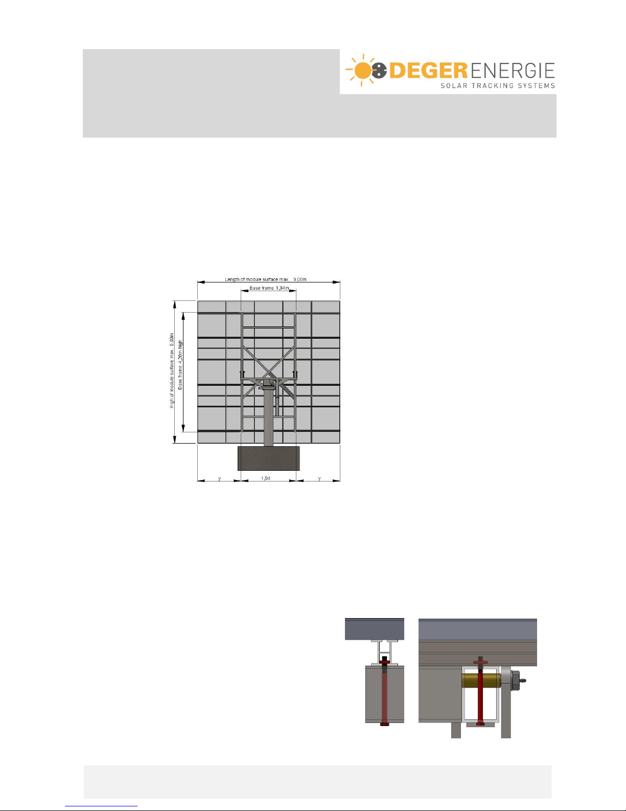
Module arrangement:
The following dimensions have to be abode and have to be reduced according to regional conditions if
necessary:
- Module surface: max. 25m²
- length of Module surface: max. 5.00m
- height of Module surface: max. 5.00m
The total module area is to be determined relative to the site with the aid of the DEGERenergie
dimensioning tool and may in no case be greater than 25m².
1st step: Arrangement of aluminium profiles:
Following points have to be attended:
- in both axis modules have to be arranged symmetrically to the center of gravity
- 2 aluminium profiles for each row of modules
- attend the connecting socket on the backside of the modules
Overhang of the aluminium profile: y= (length of aluminium profile –1.942m) / 2
2nd Step: Installation of aluminium profile F-SET-HD:
(only for DEGERtraker 3000NT and 3000HD)
Insert screw M10x140 through existing bores; slide,
align and fix Alu profile F-SET-X via the sliding nuts.
The two screws are to be tightened with a torque of 40NM.
Assembly Instruction
DEGERtraker
Part IV –Module carry system
DEGERtraker 5000NT / 5000HD
Assembly Instruction DEGERtraker 3000NT / 3000HD / 5000NT / 5000HD / 6000NT / 7000NT / 9000NT
2012-07-01
Page IV-2
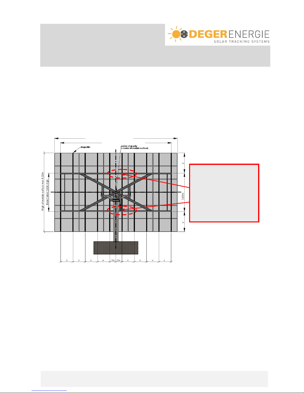
Base frame 7,20m(NT) 7,50m(HD)
Length of module surface max. 8,30m
Module arrangement:
The following dimensions have to be abode and have to be reduced according to regional conditions if
necessary:
- Module surface: max. 40m²
- length of Module surface: max. 8.30m
- height of Module surface: max. 5.30m
The total module area is to be determined relative to the site with the aid of the DEGERenergie
dimensioning tool and may in no case be greater than 40m².
1st step: Arrangement of aluminium profiles:
Distance between 2 aluminium profiles: x= width of module / 2
(attend the point of fastening from the modul manufacturer)
Overhang of the aluminium profile: y= (length of aluminium profile - 2.60m) / 2
Following points have to be attended:
- assemble aluminium profile from the middle to the outsite
- in both axis modules have to be arranged symmetrically to the center of gravity
- 2 aluminium profiles for each row of modules
- attend the connecting socket on the backside of the modules
2nd step: Assembly of aluminium profiles see Page IV-6!
In the range of the
suspension for the elevation
motor it is not possible to
assemble the MTH-clamps at
the outside of the base
frame. Here the MTH-clamps
have to be assembled at the
inside of the base frame.
Please pay attention to notes
in step 2!
This manual suits for next models
6
Table of contents
Popular Inverter manuals by other brands


Go Power
Go Power GPSW-2000 manual

Power Max
Power Max PMG4000iSR Operator's manual

Comfortaire
Comfortaire Century VFH-B Series Service manual

Sun Power
Sun Power SPR-2800 Series owner's manual

Tripp Lite
Tripp Lite PV100USB owner's manual

CanadianSolar
CanadianSolar CSI SERIES Installation and operation manual


