Sun Power SPR-2800 Series User manual

SunPower Solar
Inverter
Owner’s Manual
SPR-2800x
SPR-3300x
SPR-4000x
SPR-5000x


SunPower Solar Inverter
Owner’s Manual

Trademarks
SunPower Solar Inverter is a trademark of SunPower Corporation.
Other trademarks, registered trademarks, and product names are the property of their respective owners and are used
herein for identification purposes only.
Notice of Copyright
SunPower Solar Inverter Owner’s Manual © May 2007. All rights reserved.
Disclaimer
UNLESS SPECIFICALLY AGREED TO IN WRITING, SunPower Corporation:
(a) MAKES NO WARRANTY AS TO THE ACCURACY, SUFFICIENCY OR SUITABILITY OF ANY
TECHNICAL OR OTHER INFORMATION PROVIDED IN ITS MANUALS OR OTHER DOCUMENTATION.
(b) ASSUMES NO RESPONSIBILITY OR LIABILITY FOR LOSS OR DAMAGE, WHETHER DIRECT,
INDIRECT, CONSEQUENTIAL OR INCIDENTAL, WHICH MIGHT ARISE OUT OF THE USE OF SUCH
INFORMATION. THE USE OF ANY SUCH INFORMATION WILL BE ENTIRELY AT THE USER’S RISK.
Date and Revision
May 2007 Revision B
Manual Part Number
975-0335-01-01
SunPower Document Number
001-11872 Rev *B
Product Part Number
864-1012 (SPR-2800x), 864-1013 (SPR-3300x), 864-1014 (SPR-4000x), 864-1015 (SPR-5000x)
Contact Information
Telephone: 1 877 SUN 0123
Fax: (408) 877 1808
Email: information@sunpowercorp.com
Web: www.sunpowercorp.com

975-0335-01-01 iii
About This Manual
This Owner’s Manual provides explanations and procedures for installing,
operating, maintaining, and troubleshooting the SunPower Solar Inverter™.
Scope
The manual provides safety guidelines, detailed planning and setup information. It
provides procedures for installing the inverter and information about operating
and troubleshooting the unit. It does not provide details about particular brands of
photovoltaic (PV) panels. You need to consult individual PV manufacturers for
this information.
Audience
This manual does not provide sufficient information for anyone but a qualified
installer to install this product. Installers should be electricians or technicians fully
educated on the hazards of installing electrical equipment. The monitoring and
operation information in this manual is intended for anyone who needs to operate
a SunPower Inverter.
Organization
This manual is organized into 6 chapters and an appendix.
Chapter 1 contains information about the features and functions of the SunPower
Solar Inverter.
Chapter 2 provides information about installing the SunPower Solar Inverter. It
contains information on determining a suitable location for installation, PV array
requirements, and procedures for mounting the unit.
Chapter 3 provides information about DC and AC wiring, and grounding the
SunPower Solar Inverter and the PV array.
Chapter 4 contains information on starting up the SunPower Solar Inverter and
performing a functional test.
Chapter 5 contains information for understanding the LCD screens and the LED
indicators.
Chapter 6 contains information about how to provide general maintenance for the
SunPower Solar Inverter. It also provides information about troubleshooting the
unit.
Appendix A contains information about the specifications of the SunPower Solar
Inverter.

About This Manual
iv 975-0335-01-01
Conventions Used
The following conventions are used in this guide.
Abbreviations and Acronyms
WARNING
Warnings identify conditions that could result in personal injury or loss of life.
CAUTION
Cautions identify conditions or practices that could result in damage to the unit or other
equipment.
Important:
These notes describe things which are important for you to know, but not
as serious as a caution or warning.
CEC California Energy Commission
CSA Canadian Standards Association
GFDI Ground Fault Detector/Interrupter
LCD Liquid Crystal Display
LED Light Emitting Diode
MPPT Maximum Power Point Tracking
NEC US National Electrical Code NFPA-70
PV Photovoltaic
PVGFP PV Ground Fault Protection
STC Standard Test Condition
UL Underwriters Laboratories
Vac Volts AC
Vdc Volts DC
VMPP Voltage at Maximum Power
VOC Open Circuit Voltage

About This Manual
975-0335-01-01 v
Symbols Used
Related Information
You can find more information about SunPower Corporation at
www.sunpowercorp.com.
Ground
In this guide: Important information, warnings, or cautions.
On the product: Important information, warnings or cautions with further
explanation in the product guide.
Caution, risk of electric shock.
Hot surface—risk of burns.
Refer to the operating instructions.

vi

975-0335-01-01 vii
Important Safety Instructions
SAVE THESE INSTRUCTIONS—This manual contains important instructions that must be followed
during the installation and maintenance of the SunPower Solar Inverter.
1. Before installing and using the inverter, read all instructions and cautionary markings on the inverter,
wiring box, and all appropriate sections of this guide.
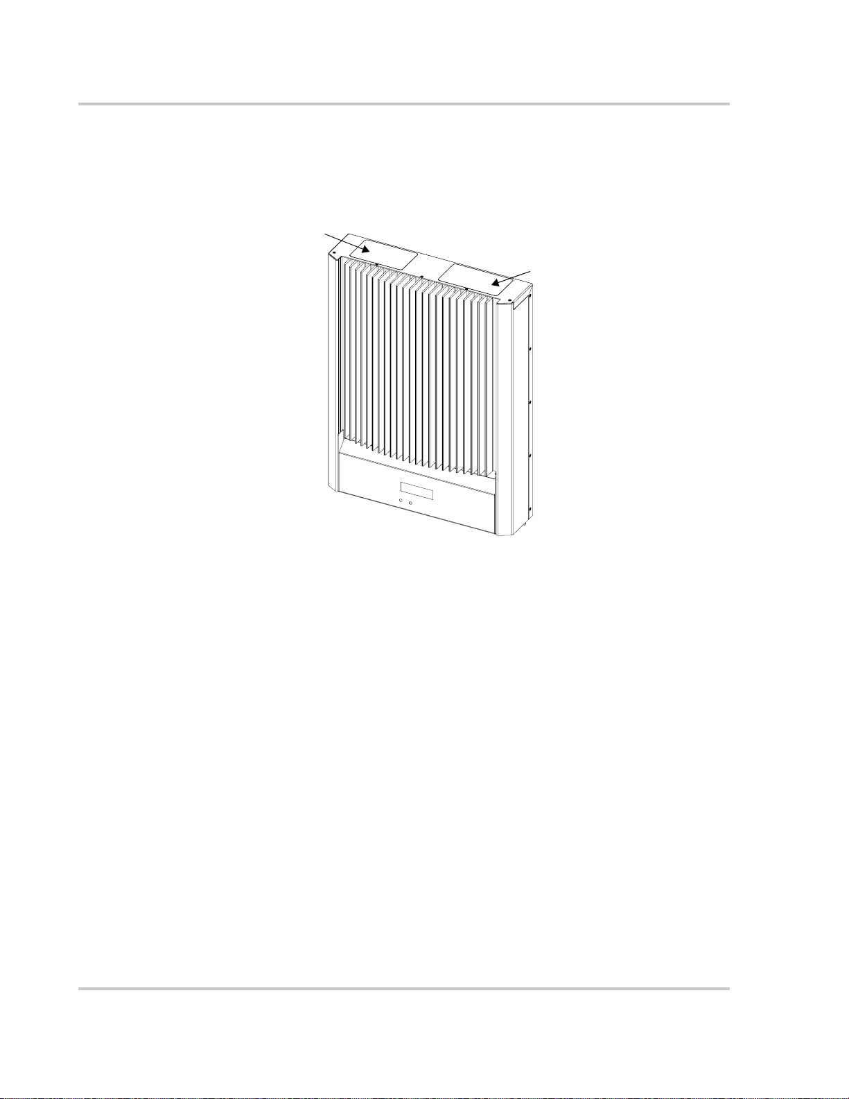
2. To reduce risk of fire hazard, do not cover or obstruct the heat sink.
3. Under some conditions, the inverter heat sink can reach temperatures hot enough to cause skin burns if
accidentally touched. Ensure that the inverter is located away from normal traffic areas.
4. Use only accessories recommended or sold by the manufacturer. Doing otherwise may result in a risk
of fire, electric shock, or injury to persons.
5. To avoid a risk of fire and electric shock, make sure that existing wiring is in good condition and that
wire is not undersized. Do not operate the inverter with damaged or substandard wiring.
6. Do not operate the inverter if it has received a sharp blow, been dropped, or otherwise damaged in any
way. If the inverter is damaged, consult your product warranty.
7. Do not disassemble the inverter. It contains no user-serviceable parts. See warranty for instructions on
obtaining service. Attempting to service the inverter yourself may result in a risk of electrical shock or
fire and will void the factory warranty.
8. Authorized service personnel should reduce the risk of electrical shock by disconnecting both AC and
DC power from the inverter before attempting any maintenance or cleaning or working on any circuits
connected to the inverter. Turning off controls will not reduce this risk. Internal capacitors remain
charged for 5 minutes after disconnecting all sources of power.
9. Normally grounded conductors may be ungrounded and energized when a ground fault is indicated.
10. The inverter must be connected to an AC equipment-grounding conductor directly and a DC
grounding electrode conductor to a single point ground.
11. The AC Neutral connection is for voltage sensing only and is not used as a current carrying conductor,
nor is it bonded to ground.
Observe the clearance recommendations as described on page 2–7. Do not install the inverter in a zero-
clearance or non-ventilated compartment. Overheating may result.
WARNING
The following warnings identify conditions or practices that could result in personal injury or loss of life.
CAUTION
The following caution identifies conditions or practices that could result in damage to the unit or other
equipment.

Safety
viii 975-0335-01-01
Location of Safety and Data Labels
The figure below shows the location of the safety label and the data label with model, serial number and
part number information.
FCC Information to the User
This equipment has been tested and found to comply with the limits for a Class B digital device, pursuant
to part 15 of the FCC Rules. These limits are designed to provide reasonable protection against harmful
interference in a residential installation. This equipment generates, uses and can radiate radio frequency
energy and, if not installed and used in accordance with the instructions, may cause harmful interference to
radio communications. However, there is no guarantee that interference will not occur in a particular
installation. If this equipment does cause harmful interference to radio or television reception, which can
be determined by turning the equipment off and on, the user is encouraged to try to correct the interference
by one or more of the following measures:
• Reorient or relocate the receiving antenna.
• Increase the separation between the equipment and the receiver.
• Connect the equipment into an outlet on a circuit different from that to which the receiver is connected.
• Consult the dealer or an experienced radio/TV technician for help.
Safety Label
Data Label

975-0335-01-01 ix
Important Safety Instructions - - - - - - - - - - - - - - - - - - - - - - - - - - - - - - - - vii
Location of Safety and Data Labels - - - - - - - - - - - - - - - - - - - - - - - - - - - - - - - - - - - - - - - - - - viii
FCC Information to the User - - - - - - - - - - - - - - - - - - - - - - - - - - - - - - - - - - - - - - - - - - - - - - - viii
1
Introduction
About the SunPower Solar Inverter - - - - - - - - - - - - - - - - - - - - - - - - - - - - - - - - - - - - - - - - - 1–1
Standard Features - - - - - - - - - - - - - - - - - - - - - - - - - - - - - - - - - - - - - - - - - - - - - - - - - - - - 1–2
Front Panel Features - - - - - - - - - - - - - - - - - - - - - - - - - - - - - - - - - - - - - - - - - - - - - - - - - - 1–3
Wiring/Disconnect Box - - - - - - - - - - - - - - - - - - - - - - - - - - - - - - - - - - - - - - - - - - - - - - - - 1–3
2
Installation
Installation Options - - - - - - - - - - - - - - - - - - - - - - - - - - - - - - - - - - - - - - - - - - - - - - - - - - - - 2–1
Planning the Installation - - - - - - - - - - - - - - - - - - - - - - - - - - - - - - - - - - - - - - - - - - - - - - - - - 2–1
Inverter Location - - - - - - - - - - - - - - - - - - - - - - - - - - - - - - - - - - - - - - - - - - - - - - - - - - - - 2–1
PV Array Voltage and MPPT Requirements - - - - - - - - - - - - - - - - - - - - - - - - - - - - - - - - - - 2–3
Mounting the Inverter - - - - - - - - - - - - - - - - - - - - - - - - - - - - - - - - - - - - - - - - - - - - - - - - - - 2–5
Dimensions and Knockout Locations - - - - - - - - - - - - - - - - - - - - - - - - - - - - - - - - - - - - - - 2–5
Installing the Mounting Bracket - - - - - - - - - - - - - - - - - - - - - - - - - - - - - - - - - - - - - - - - - - 2–6
Mounting the Inverter on the Bracket - - - - - - - - - - - - - - - - - - - - - - - - - - - - - - - - - - - - - - 2–8
3
Wiring the Inverter
Grounding Requirements - - - - - - - - - - - - - - - - - - - - - - - - - - - - - - - - - - - - - - - - - - - - - - - - 3–1
Ground Fault Fuse - - - - - - - - - - - - - - - - - - - - - - - - - - - - - - - - - - - - - - - - - - - - - - - - - - - 3–3
Wiring Requirements - - - - - - - - - - - - - - - - - - - - - - - - - - - - - - - - - - - - - - - - - - - - - - - - - - - 3–4
AC Circuit Breaker Requirements - - - - - - - - - - - - - - - - - - - - - - - - - - - - - - - - - - - - - - - - - 3–4
DC/AC Disconnect Switch - - - - - - - - - - - - - - - - - - - - - - - - - - - - - - - - - - - - - - - - - - - - - 3–4
Accessing the Wiring Terminals - - - - - - - - - - - - - - - - - - - - - - - - - - - - - - - - - - - - - - - - - - - 3–5
Connecting the DC Wiring - - - - - - - - - - - - - - - - - - - - - - - - - - - - - - - - - - - - - - - - - - - - - - - 3–7
DC Wiring for Multiple Inverters - - - - - - - - - - - - - - - - - - - - - - - - - - - - - - - - - - - - - - - - - 3–9
Connecting the AC Wiring - - - - - - - - - - - - - - - - - - - - - - - - - - - - - - - - - - - - - - - - - - - - - - - 3–10
DC and AC Wiring for Multiple Inverters - - - - - - - - - - - - - - - - - - - - - - - - - - - - - - - - - - - - - 3–11
Communications Wiring for Multiple Inverters - - - - - - - - - - - - - - - - - - - - - - - - - - - - - - - - - 3–12
Network Layout - - - - - - - - - - - - - - - - - - - - - - - - - - - - - - - - - - - - - - - - - - - - - - - - - - - - 3–12
Guidelines for Routing the Network Cables - - - - - - - - - - - - - - - - - - - - - - - - - - - - - - - - - 3–15
Connecting Network Cable Between Multiple Inverters - - - - - - - - - - - - - - - - - - - - - - - - - 3–15
Contents

Contents
x975-0335-01-01
4
Starting the Inverter
Startup Procedure- - - - - - - - - - - - - - - - - - - - - - - - - - - - - - - - - - - - - - - - - - - - - - - - - - - - - - 4–1
Checking the PV Array DC Voltage - - - - - - - - - - - - - - - - - - - - - - - - - - - - - - - - - - - - - - - 4–1
Checking the AC Utility Voltage - - - - - - - - - - - - - - - - - - - - - - - - - - - - - - - - - - - - - - - - - 4–2
Replacing the Wiring/Disconnect Box Cover - - - - - - - - - - - - - - - - - - - - - - - - - - - - - - - - - 4–3
Starting up the Inverter - - - - - - - - - - - - - - - - - - - - - - - - - - - - - - - - - - - - - - - - - - - - - - - 4–3
Commissioning Multiple Inverters - - - - - - - - - - - - - - - - - - - - - - - - - - - - - - - - - - - - - - - - - - 4–4
Disconnect Test - - - - - - - - - - - - - - - - - - - - - - - - - - - - - - - - - - - - - - - - - - - - - - - - - - - - - - - 4–6
Locating the Firmware Version Number- - - - - - - - - - - - - - - - - - - - - - - - - - - - - - - - - - - - - - - 4–6
5
Monitoring the Inverter
Monitoring the Front Panel Display- - - - - - - - - - - - - - - - - - - - - - - - - - - - - - - - - - - - - - - - - - 5–1
Front Panel Display Screens and What They Mean - - - - - - - - - - - - - - - - - - - - - - - - - - - - - - - 5–2
Startup Mode - - - - - - - - - - - - - - - - - - - - - - - - - - - - - - - - - - - - - - - - - - - - - - - - - - - - - - 5–2
Normal Operation Mode - - - - - - - - - - - - - - - - - - - - - - - - - - - - - - - - - - - - - - - - - - - - - - 5–4
Offline Mode - - - - - - - - - - - - - - - - - - - - - - - - - - - - - - - - - - - - - - - - - - - - - - - - - - - - - - 5–6
Fault Mode - - - - - - - - - - - - - - - - - - - - - - - - - - - - - - - - - - - - - - - - - - - - - - - - - - - - - - - - 5–8
Special Screens - - - - - - - - - - - - - - - - - - - - - - - - - - - - - - - - - - - - - - - - - - - - - - - - - - - - -5–10
Custom Screens - - - - - - - - - - - - - - - - - - - - - - - - - - - - - - - - - - - - - - - - - - - - - - - - - - - -5–10
Status Indicator Lights- - - - - - - - - - - - - - - - - - - - - - - - - - - - - - - - - - - - - - - - - - - - - - - - - - 5–11
6
Maintenance and Troubleshooting
Factors Affecting Inverter Performance - - - - - - - - - - - - - - - - - - - - - - - - - - - - - - - - - - - - - - - 6–1
PV Array Factors - - - - - - - - - - - - - - - - - - - - - - - - - - - - - - - - - - - - - - - - - - - - - - - - - - - 6–1
Other Factors - - - - - - - - - - - - - - - - - - - - - - - - - - - - - - - - - - - - - - - - - - - - - - - - - - - - - - 6–2
Performing General Maintenance - - - - - - - - - - - - - - - - - - - - - - - - - - - - - - - - - - - - - - - - - - - 6–3
Replacing Parts - - - - - - - - - - - - - - - - - - - - - - - - - - - - - - - - - - - - - - - - - - - - - - - - - - - - - - - 6–4
Replacing the Ground Fault Protection Fuse - - - - - - - - - - - - - - - - - - - - - - - - - - - - - - - - - 6–4
Replacing the Inverter - - - - - - - - - - - - - - - - - - - - - - - - - - - - - - - - - - - - - - - - - - - - - - - - 6–6
Identifying Error/Fault Conditions and Solutions- - - - - - - - - - - - - - - - - - - - - - - - - - - - - - - - - 6–9
A
Specifications
Electrical Specifications - - - - - - - - - - - - - - - - - - - - - - - - - - - - - - - - - - - - - - - - - - - - - - - - - A–2
SPR-5000x - - - - - - - - - - - - - - - - - - - - - - - - - - - - - - - - - - - - - - - - - - - - - - - - - - - - - - - - A–2
SPR-4000x - - - - - - - - - - - - - - - - - - - - - - - - - - - - - - - - - - - - - - - - - - - - - - - - - - - - - - - - A–4
SPR-3300x - - - - - - - - - - - - - - - - - - - - - - - - - - - - - - - - - - - - - - - - - - - - - - - - - - - - - - - - A–6
SPR-2800x - - - - - - - - - - - - - - - - - - - - - - - - - - - - - - - - - - - - - - - - - - - - - - - - - - - - - - - - A–8
Adjustable Voltage, Frequency and Reconnection Settings - - - - - - - - - - - - - - - - - - - - - - A–10
Output Power Versus Ambient Temperature- - - - - - - - - - - - - - - - - - - - - - - - - - - - - - - - - - - A–10
Environmental Specifications- - - - - - - - - - - - - - - - - - - - - - - - - - - - - - - - - - - - - - - - - - - - - A–11

Contents
975-0335-01-01 xi
User Display- - - - - - - - - - - - - - - - - - - - - - - - - - - - - - - - - - - - - - - - - - - - - - - - - - - - - - - - A–11
Display Accuracy - - - - - - - - - - - - - - - - - - - - - - - - - - - - - - - - - - - - - - - - - - - - - - - - - - -A–11
Mechanical Specifications - - - - - - - - - - - - - - - - - - - - - - - - - - - - - - - - - - - - - - - - - - - - - - A–11
Regulatory Approvals - - - - - - - - - - - - - - - - - - - - - - - - - - - - - - - - - - - - - - - - - - - - - - - - - A–12
Information About Your System - - - - - - - - - - - - - - - - - - - - - - - - - - - - - - - - - - - - - - - - - - A–13
Index- - - - - - - - - - - - - - - - - - - - - - - - - - - - - - - - - - - - - - - - - - - - - - - - - - -IX–1

xii

1Introduction
Chapter 1 contains information about the features and functions of the
SunPower Solar Inverter.
About the SunPower Solar Inverter
The SunPower Solar Inverter is designed to convert solar electric (photovoltaic or
PV) power into utility-grade electricity that can be used by the home or sold to the
local power company.
Installing the inverter consists of mounting it to the wall and connecting the DC
input to a PV array and the AC output to the utility. See Figure 1-1 for a simple
diagram of a typical installation.
In order to operate, the inverter must have grid power available and connected. It
will not provide backup power if the AC grid fails.
Figure 1-1
Basic System Overview
Harvested
solar energy
Photovoltaic
(PV) array
Utility grid
Utility meter
Surplus power
routed to utility grid
Power routed
to loads
Main utility
service panel
SunPower Inverter

Introduction
1–2 975-0335-01-01
PV compatibility The inverter is designed to take advantage of solar modules configured as high-
voltage PV string arrays—single crystalline, poly crystalline, or thin film—with
an input voltage Maximum Power Point range (depending on inverter model) of
195 to 550 Vdc, 240 to 550 Vdc, 240 to 480, or 200 to 400 Vdc. See “Electrical
Specifications” on page A–2 for more information.
Utility grid
compatibility The inverter can operate on either 240 V or 208 V nominal grid voltage. The
inverter senses the phase-to-phase voltage and automatically changes the power
limit value for each grid voltage. The disconnect thresholds (see “Adjustable
Voltage, Frequency and Reconnection Settings” on page A–10) remain the same
because both nominal voltages have the same 120 Vac phase-to-neutral
thresholds.
Maximum Power
Point Tracking
(MPPT)
The inverter uses a proprietary Maximum Power Point Tracking (MPPT)
technology to harvest the maximum amount of energy from the solar array. MPPT
learns your array’s specific characteristics, maximizing its output at all times.
High efficiency The high-frequency, solid-state design of the inverter is extremely efficient. See
Appendix A, “Specifications” for the efficiency ratings of each model.
Expandable Multiple inverters may be networked together for increased net metering capacity
or future system growth. The inverter has adjustable voltage and frequency
disconnect settings and can be aggregated above 30 kW on a single point-of-
common-coupling (PCC). See “Adjustable Voltage, Frequency and Reconnection
Settings” on page A–10.
Standard Features
The inverter has the following standard features:
• Sealed inverter section protecting power electronic components;
• Liquid Crystal Display (LCD) providing easy-to-read system status and daily
cumulative energy production information;
• Two LED indicator lights providing status and ground fault indication;
• Wiring/disconnect box providing protection for all AC and DC connections
and eliminating exposed “live” wiring if the inverter is removed.
The wiring/disconnect box has been designed to be physically mated to the
electronics section of the SunPower Inverter at the factory, but remains in
place as a non-serviceable item in the event that the inverter electronics
section is ever required to be removed. The inverter and wiring/disconnect
box together form an NEMA 3R enclosure to allow outdoor installation.

About the SunPower Solar Inverter
975-0335-01-01 1–3
Front Panel Features
Wiring/Disconnect Box
The wiring/disconnect box is standard for all North American models of the
inverter. The wiring/disconnect box provides a location for making AC, DC and
ground connections. It also contains the DC/AC (PV array/utility) disconnect
switch. When used with the inverter, the DC/AC disconnect switch is 600V AC
and DC rated and is identified on the outside by an illustration showing the open
and closed switch positions. The switch is lockable, and meets NEC Section 690
requirements as a means of disconnect.
WARNING: Shock hazard
The 600 volt DC/AC disconnect in the wiring/disconnect box meets NEC Article 690. It is
a non-serviceable component and shall remain in place. Separating the inverter and
wiring/disconnect box, or removing the wiring/disconnect box cover can expose
energized conductors. PV input circuits in the wiring box ahead of the switch remain
energized even when the switch is in the “off” position—hazardous voltage will still be
present on the DC input (PV) terminals under the clear plastic insulation barrier inside the
wiring/disconnect box.
Figure 1-2
Front Panel Features
LED Indicators
DC/AC Disconnect Switch
Mounting Slots
Heat Sink
LCD
Wiring/Disconnect Box

In jurisdictions where the local utility requires that the AC disconnect be capable
of being locked in the open position by its service personnel, this disconnect
switch can also serve as a lockable isolating device.
Important:
In North America and other locations the wiring/disconnect box is an
electrical code requirement. Regulatory approval is based on the wiring/disconnect box
always being attached to the inverter during operation. Any attempt to remove this box
will invalidate the approvals and create an electrical hazard.

2Installation
Chapter 2 provides information about installing the SunPower Solar
Inverter. It contains information on determining a suitable location for
installation, PV array requirements, and procedures for mounting the unit.
Installation Options
The inverter may be installed as a single inverter for a single PV array of one to
three PV strings. Only SPR-5000x models can accept three PV strings. An
external fuse box may be required when three PV strings are connected.
The inverter can also be installed in a multiple inverter configuration. If multiple
inverters are used, each inverter must be wired to an independent PV array.
Communications between inverters can be enabled by installing network cabling
to the inverter RJ-45 ports. See “Connecting Network Cable Between Multiple
Inverters” on page 3–15.
Planning the Installation
Ensure that you have obtained all permits required by local authorities or utilities
before beginning installation.
Inverter Location
WARNING: Burn hazard
Do not install in a location where people can accidentally come into contact with the front
of the inverter. High temperatures can be present on the face of the inverter, causing a
potential burn hazard.
In extreme conditions, the inverter chassis can reach temperatures over 70° C (158° F),
which can cause skin burns if accidentally touched. Ensure that the inverter is located
away from normal traffic areas.

Installation
2–2 975-0335-01-01
Inverter failure due to improper installation will void the inverter warranty.
Consider the following when determining where to install the inverter.
Indoor/
Outdoor • The inverter uses a Type 3R-rated enclosure (vertical mount only) that
can be mounted indoors or outdoors. (Type 3R enclosures are intended
for outdoor use primarily to provide a degree of protection against
falling rain; and to be undamaged by the formation of ice on the
enclosure.)
• While the 3R-rated enclosure protects the inverter from moisture,
outdoor installations should be located away from lawn sprinklers and
other sources of spray.
• A sun shade is recommended for outdoor installations. In bright sun
conditions, when the inverter is at or near full output with an ambient
temperature above 40 °C (104 °F), shading the unit will help increase
inverter performance. A sun shade can also protect the inverter from
dust, debris, and birds. The sun shade should be made from an opaque
material to provide shade for the heat sink. It should be large enough
and positioned so that it shades the heat sink when the inverter is
operating at full power—usually a four-hour time period centered
around noon. Ensure that the shade is installed according to the
minimum clearances specified on page 2–7.
Orientation • The inverter must be mounted vertically on a wall or pole.
• Do not mount the inverter horizontally.
• If mounting the inverter indoors on a south-facing wall, ensure the wall
is insulated to reduce the amount of heat absorbed by the inverter.
Unless walls are properly insulated, avoid mounting the inverter
indoors on any wall that is directly exposed to the sun.
Temperature • Ensure that the inverter is mounted in a location where the ambient
temperature range is -25 to +65 °C (-13 to +149 °F).
• Above 40 °C (104 °F), the inverter may derate power output.
See“Output Power vs. Ambient Temperature” on page A–3 and
“Environmental Specifications” on page A–4.
• At extreme cold temperatures, the front panel LCD may not function
normally.
Ground
Clearance • Outdoors, the inverter requires at least 100 cm (39 inches) of clearance
between the bottom of the unit and the ground.
Distance • To minimize resistance and resulting power loss, ensure that wire
lengths between the PV array and the inverter and between the inverter
and the main utility service panel are kept to a minimum.
• Maximum distances will depend on wire gauges used and PV array
output voltages.
Debris free • Excessive debris (such as dust, leaves, and cobwebs) can accumulate
on the unit, interfering with wiring connections and ventilation. Do not
install in a location where debris can accumulate (under a tree, for
example).
This manual suits for next models
3
Table of contents
Other Sun Power Inverter manuals
Popular Inverter manuals by other brands

LG
LG N1T-V Series installation manual

Champion Global Power Equipment
Champion Global Power Equipment 200953 Operator's manual

World Friendship
World Friendship WF-600T Series user manual

Fujitsu
Fujitsu Comfort Series Service manual

Magnum Energy
Magnum Energy RD Series owner's manual

SolarMax
SolarMax MT Series instruction manual

Cloos
Cloos GLW 222 AC/DC Operating instructions and spare parts

DieHard
DieHard DH139 Operator's manual

Mitsubishi Electric
Mitsubishi Electric FR-A7AL instruction manual

ABB
ABB ACS880-107 Hardware manual

Technaxx
Technaxx TE23 user manual

Generac Power Systems
Generac Power Systems Guardian Elite 005259-0 owner's manual