DEGREE C Rooster Sensor 100 User manual
Rooster™Sensor100 USER MANUAL
Rooster TM Sensor100 USER MANUAL 62320MN000-A04 1
This is proprietary information of Degree Controls Inc., contents are protected under US copyright laws © Degree Controls, Inc. 2021
High Performance Air Velocity and
Temperature Sensor
with Full-Color Touch Screen Display
Complete Kit includes:
oSensor Display Panel
oSensor Probe and Mounting Clamp
oPower Supply
1.06

Rooster™Sensor100 USER MANUAL
Rooster TM Sensor100 USER MANUAL 62320MN000-A04 2
Contents
Product Overview .................................................................................................................................................................................3
Hard Button Overview....................................................................................................................................................................3
Soft Buttons and Home Screen....................................................................................................................................................4
Feature Overview .............................................................................................................................................................................4
Rear Panel Layout for Advanced Connections.......................................................................................................................6
Technical Specifications.....................................................................................................................................................................7
Connection and Wiring Information.............................................................................................................................................7
Night Setback Input.........................................................................................................................................................................8
Alarm Output.....................................................................................................................................................................................8
Installation...............................................................................................................................................................................................8
Back Plate Mounting Options - Alarm Module .....................................................................................................................8
Installation Procedure.....................................................................................................................................................................9
Probe Sensor ................................................................................................................................................................................... 10
Boot Up Procedure ........................................................................................................................................................................... 12
Access Tier Privileges: USER, EH&S & CERTIFIER ................................................................................................................ 12
Set/Change Passwords.................................................................................................................................................................... 13
Alarm Threshold Configuration ................................................................................................................................................... 13
Alarm Troubleshooting ............................................................................................................................................................... 14
Alarm Controls.................................................................................................................................................................................... 14
Night Setback ................................................................................................................................................................................. 15
Alarm Ringback ............................................................................................................................................................................. 15
Alarm Delay .................................................................................................................................................................................... 16
Startup Delay.................................................................................................................................................................................. 16
Latch Alarm..................................................................................................................................................................................... 16
Alarm Tone Settings..................................................................................................................................................................... 17
Backlight Dimming............................................................................................................................................................................ 17
Airflow Settings .................................................................................................................................................................................. 18
Airflow Sensitivity.......................................................................................................................................................................... 18
Airflow Resolution......................................................................................................................................................................... 18
Volumetric Flow Settings............................................................................................................................................................ 18
Analog Output.................................................................................................................................................................................... 19
I/O Polarity........................................................................................................................................................................................... 20
Import/Export ..................................................................................................................................................................................... 20
EEPROM............................................................................................................................................................................................ 20
Event Log.......................................................................................................................................................................................... 20
USB Field Upgrade Procedure...................................................................................................................................................... 21
Soft Reboot from Info Screen .................................................................................................................................................... 22
Power Cycle Procedure................................................................................................................................................................ 22
Factory Reset Procedure................................................................................................................................................................. 23
GUI Map ................................................................................................................................................................................................ 24
Warranty................................................................................................................................................................................................ 25
Rooster™Sensor100 USER MANUAL
Rooster TM Sensor100 USER MANUAL 62320MN000-A04 3
Product Overview
Congratulations on your purchase of the RoosterTM Sensor100, the next-generation air velocity
and temperature sensor, a monitoring and alarm system for critical HVAC and process control
applications where airflow is required to be viewed, monitored, alarmed, and even
communicated to building and laboratory systems.
Degree Controls Inc. designed the RoosterTM Sensor100 to meet the demand for high
performance air velocity and temperature sensing applications and uses an intuitive, glove-
friendly, color touchscreen interface, and best-in-class air velocity sensing. This product is design
with a probe style sensor to reach into ducted flows in building, process, datacenter and HVAC
applications. An instrumentation class sensor is used to eliminate trouble alarms and provide
best accuracy across wide temperature ranges. The RoosterTM Sensor100 comes calibrated with
NIST certificate, from 0.15 –20.0 m/s [30 –4000 fpm]. Different calibration ranges can be
ordered, for more information, contact Degree Controls, Inc.
The RoosterTM Sensor100 uses a bright, backlit display and contains many simple-to-use
features, and configuration capabilities, built into an intuitive user interface that requires little to
no training to learn. Password-protected access tiers ensure greater safety in a range of
environments by limiting access to critical functions and system settings for specific, authorized
users. The RoosterTM Sensor100 is the first airflow sensor with USB-based plug and play firmware
upgrades, to keep your product current and operating to the latest standards.
This manual will guide you through installation, firmware upgrades, alarm control settings, and
the full range of features for the RoosterTM Sensor100.
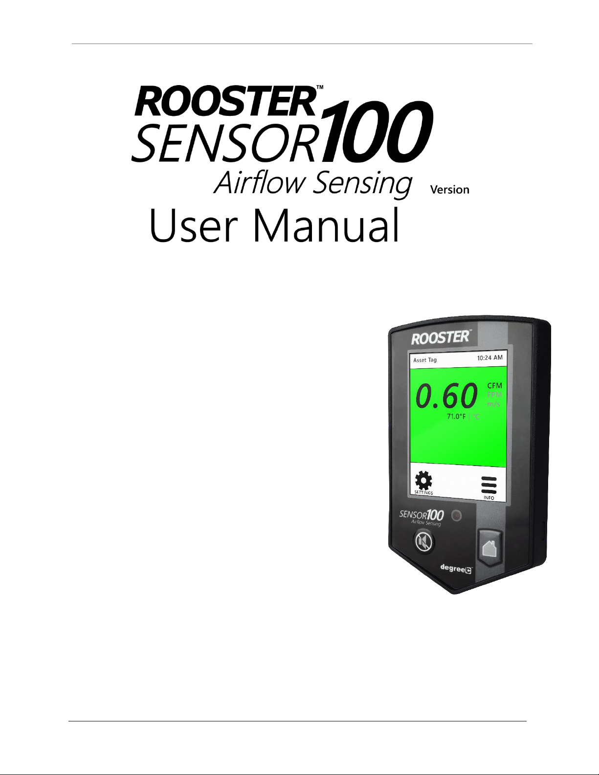
Hard Button Overview
MUTE
Mutes the audible alarm, any time it is sounding. When the alarm has
been muted, a mute icon [ ] will appear in the top center portion of
the home screen. Just like a snooze button, the audible alarm will re-
sound, when the configurable time-out is reached if ringback has been
enabled.
HOME
Returns the user to the home screen when pushed from any menu or
info screen. *Cannot be used to abort some critical system functions.*
LED
This red LED will flash while an airflow alarm is active. The red LED will
also flash if Night Setback alarm is active. In all other cases, this LED will
remain off.
Rooster™Sensor100 USER MANUAL
Rooster TM Sensor100 USER MANUAL 62320MN000-A04 4
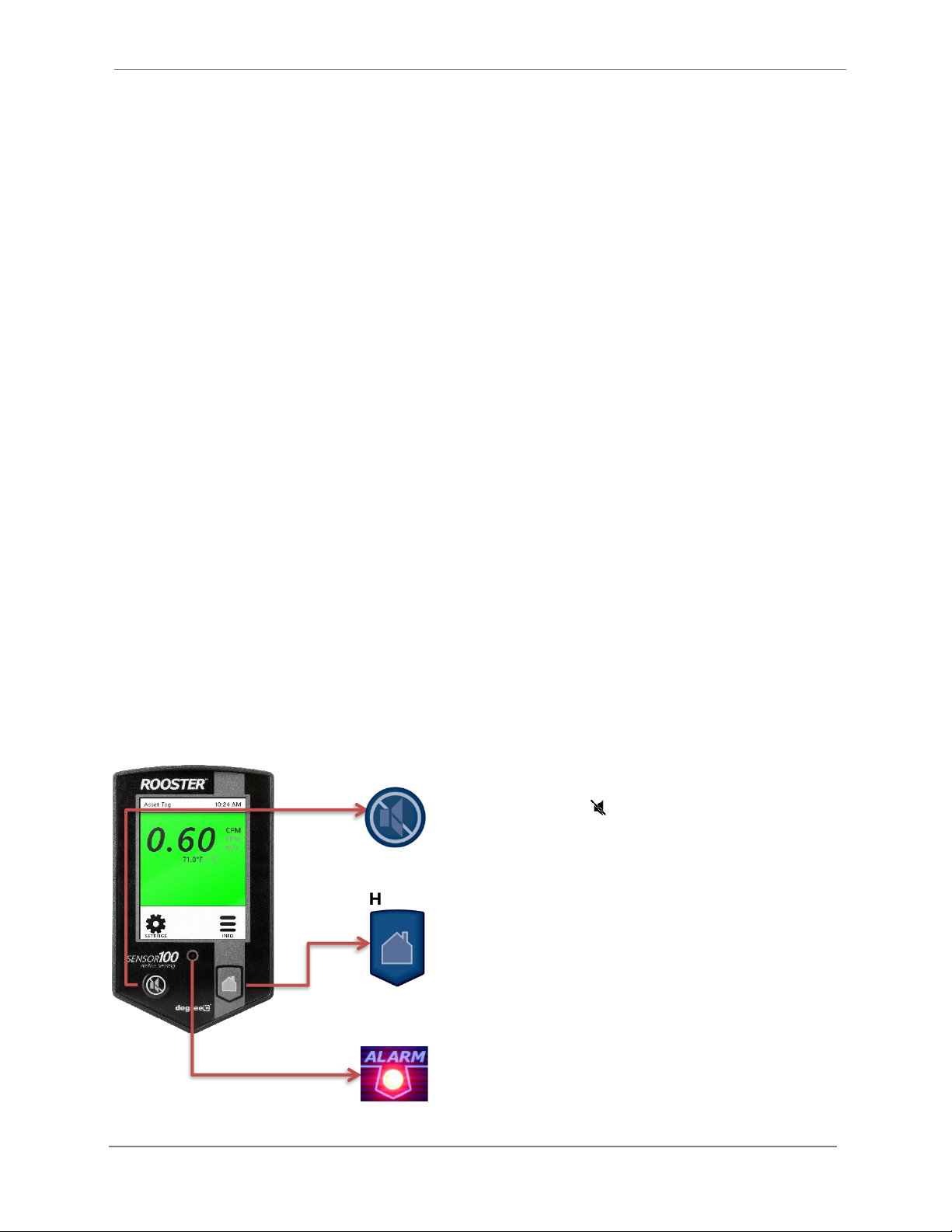
Soft Buttons and Home Screen
Feature Overview
CUSTOM ASSET TAG
Users logged in as EH&S can change default “Asset Tag” to a custom tag. This is useful for
naming the sensor in larger distributed systems, or to denote a company asset number. The user
may set a 12-digit numeric asset tag with the provided on-screen keypad OR plug in a USB
interface keyboard to enter a 12-character alphanumeric tag.
Home>Settings>System>Advanced>Configure Asset Tag
CLOCK
Users logged in as EH&S or Certifier can set time, date and change clock to display in 12 or 24
hour format.
Home>Settings>System>Time>Date and Time Settings
KEYPAD SOUNDS
Users may toggle keypad beep sounds on and off.
Home>Settings>System>Alarms/Sound>Key Beep
ALARM VOLUME
Users can toggle through low, medium, or high alarm volumes. If logged in as an EH&S or
Certifier, a global minimum volume threshold can be set. This restricts a standard user from
setting an alarm volume too low for particular facility safety requirements.
Home>Settings>System>Alarms/Sound>Device Volume
Asset Tag
Air Velocity
(touch to toggle units)
Air Temperature
(touch to toggle units)
Settings Menu
USB input for keyboard
and firmware upgrades
Time of Day
Alert Banner
Quick access to current
configuration settings including
alarm thresholds, calibration date,
and firmware version
Status Color (Green, Yellow or Red)
Startup Delay Indicator,
Night Setback/Mute Indicator

Rooster™Sensor100 USER MANUAL
Rooster TM Sensor100 USER MANUAL 62320MN000-A04 5
ON-SCREEN ALERT BANNERS
A yellow banner will appear beneath on-screen velocity readings to alert users of the following
scenarios: 1) Uncalibrated Sensor 2) Sensor Failure 3) Low Airflow. Alarm latched status will also
display here.
Home
TOGGLE VELOCITY UNIT TYPE
Instantly toggle displayed velocity units between m/s, fpm, or cfm by pressing on the displayed
velocity reading on the home screen.
Home
TOGGLE TEMPERATURE TYPE
Instantly toggle displayed temperature units from Fahrenheit to Celsius or vice versa by pressing
on the displayed temperature reading on the home screen.
Home
PASSWORD-PROTECTED ACCESS TIERS: CERTIFIER & EH&S
Password protected access tiers enable advanced configuration options and features.
Home>Settings>System>Advanced>Change Passwords
USB INTERFACE FOR FIELD UPGRADE PROCEDURE AND DATA IMPORT/EXPORT
Firmware upgrades can be installed on-site via USB flash drive. See the USB Field Upgrade
section for more information. Users may also import/export Rooster™ settings and export the
event log through the USB interface.
CUSTOMIZABLE BOOT SCREEN
Our engineers can configure your unit with a custom image or logo file (240x320) in portable
network graphic (.png) format to display on bootup. Contact our sales team to get started:
sales@degreec.com
NIGHT SETBACK
EH&S or Certifier users can configure three convenient modes (Audible, Muted, or Off) of
operation. The RoosterTM Sensor100 is a normally open (NO) device, to trigger audible or muted
night setback, the dry contact relay must be closed. See the “Alarm Threshold Configuration”
section for instructions on how to setup night setback alarm thresholds.
Home>Settings>System>Alarms/Sound>Alarm Controls>Night Setback
ALARM LATCHING
EH&S or Certifier users can setup latched alarms to indicate that a low airflow state has occurred
in the “Alarm Controls” menu. The user must then enter EH&S or Certifier passcode to unlatch
Table of contents


