DEHAS Quality Mix High Flow User manual


Table of Contents
1. Explanation of the key abbreviations............................................................................ 2
2. Safety information –Warnings, precautions and identification
information.............................................................................................................................. 2
3. Contents of delivery; Inspection upon receipt .......................................................... 4
4. Intended usage...................................................................................................................... 5
5. Before initial usage .............................................................................................................. 5
6. Technical specifications ...................................................................................................... 7
7. Pressure drop in the system............................................................................................. 8
8. Transportation and storage conditions......................................................................... 9
9. Dryness and composition of the supply gases .......................................................... 9
10. Illustrations and identification of components .......................................................... 9
11. Installation ............................................................................................................................ 12
12. Alarm test .............................................................................................................................. 12
13. Initial use ............................................................................................................................... 13
14. Cleaning / disinfection ...................................................................................................... 14
15. Maintenance.......................................................................................................................... 15
16. Product returns.................................................................................................................... 16
17. Disposal .................................................................................................................................. 16
18. Troubleshooting................................................................................................................... 17
19. Warranty conditions........................................................................................................... 18
20. Part numbers........................................................................................................................ 19
Status: 03/2022

2
1. Explanation of the key abbreviations
FIO2
Fractional concentration of inspiratory oxygen
DISS
Diameter Index Safety System
NIST
Non-Interchangeable Screw Thread
Bar
Measurement unit for pressure
l/min
litre per minute
2. Safety information –Warnings, precautions and
identification information
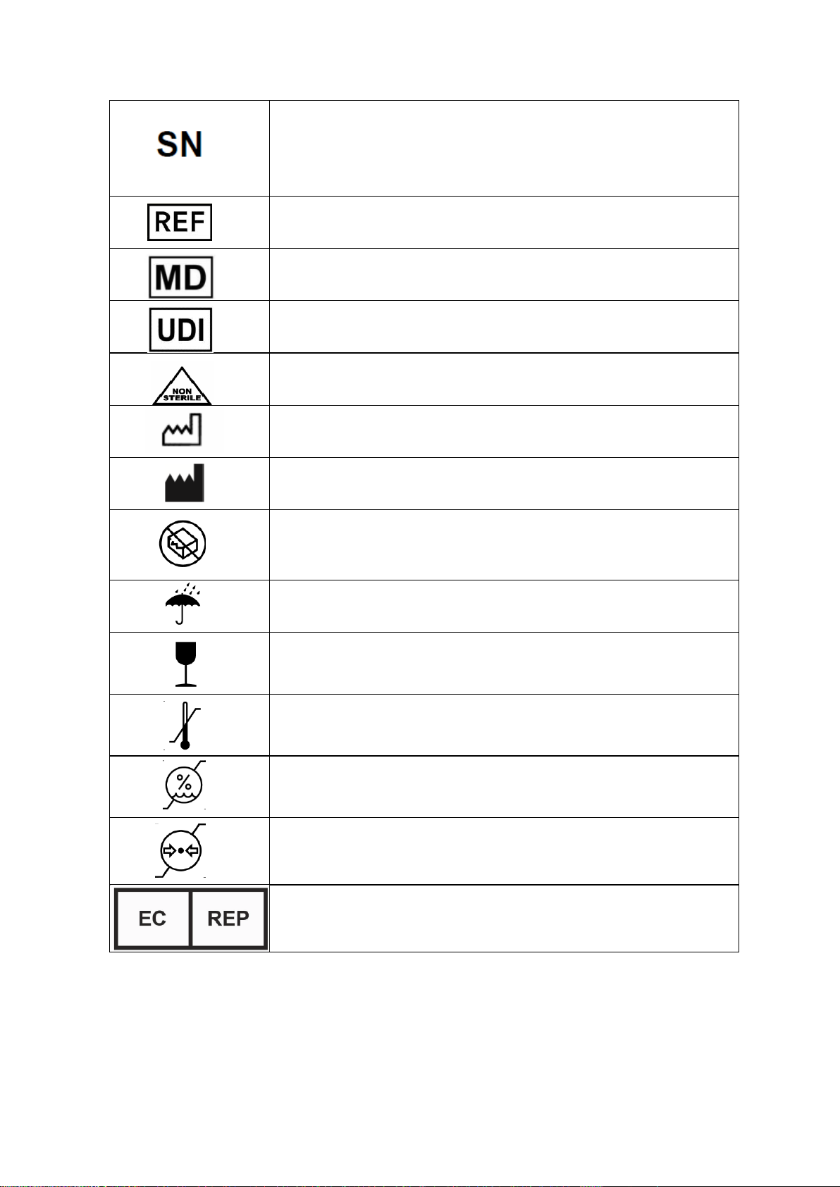
Symbol
Description
This symbol indicates that the device complies with the
regulation 93/42/EEC concerning medical devices and all
applicable international standards.
WARNING
Indicates a potentially hazardous situation which, if not
avoided, could result in death or serious injury.
CAUTION
CAUTION is used to indicate a potentially hazardous
situation which, if not avoided, may result in property
damage.
or
Refers the user to the necessity of consulting the
operating instructions.
Follow the instructions!
DO NOT USE OIL
3
Shows the serial number of the manufacturer so that a
certain medical product can be identified.
Shows the order number of the manufacturer so that
the medical product can be identified.
Medical device
UDI Barcode
Non-sterile
Date of manufacture
Show the manufacturer of the medical product according
to the EU guidelines 90/385/EEC, 93/42/EEC and
98/79/EC.
Shows a medical product that should not be used if the
packaging is damaged or opened
Describes a medical product that must be protected
against humidity.
Describes a medical product which can break or be
damaged if not handled with care.
Describes the temperature limit values that the medical
product can be safely exposed to.
Describes the humidity range that the medical product
can be safely exposed to.
Describes the atmospheric pressure range that the
medical product can be safely exposed to.
EU Authorised Representative

4
3. Contents of delivery; Inspection upon receipt
Contents of the delivery: 1 Base mixer along with any additional components
specified for your order
1 Operating instructions
Inspection: Take the device out of its packaging and inspect it for
damage. Do NOT use the device if you find any
damage. Contact your retailer.
5
4. Intended usage
The air-oxygen mixer Quality Mix is used to administer a continuous, precise mix
of medical air and medical oxygen –through its outlet ports –to infants, children
and adults. The exact fractional inspiratory oxygen concentration (FIO2)
corresponds to the selected FIO2setting on the control knob (dial).
Indication: This device should be used for patients who find it difficult to get
sufficient oxygen from the ambient air.
Contraindications: This device should not be used for patients who cannot breathe
on their own. Do not use for life support or life saving
procedures.
5. Before initial usage
Read all instructions before use!
These operating instructions are intended to show trained professionals how to
install and operate the Quality Mix. They promote safety and protect your device
from damage. If you do not understand information or instructions in this
document, do not use the device and contact your supplier.
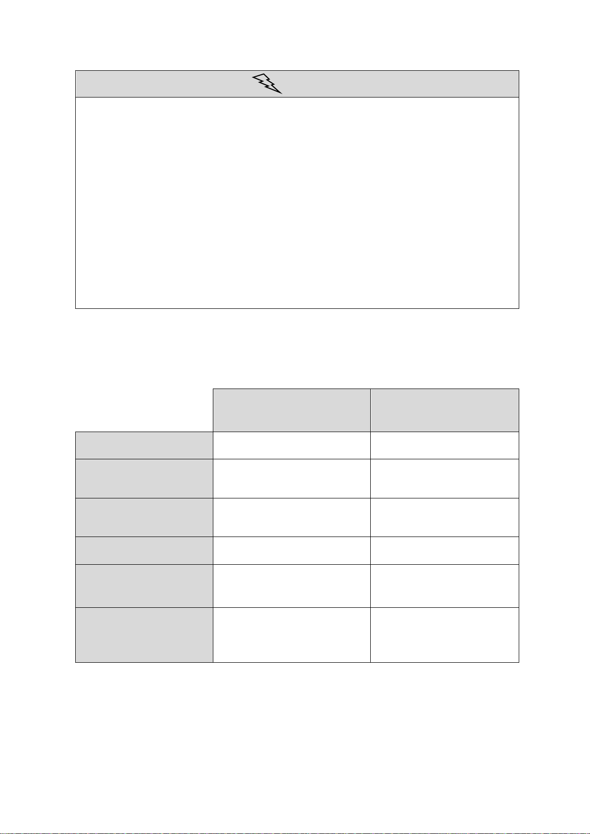
DANGER
This product is not intended for use as a life-sustaining or life-supporting device.

6
WARNING
The air-oxygen mixer should only be operated by trained medical
professionals under the direct supervision of a licensed physician.
Use this air-oxygen mixer only for the purpose described in these
instructions.
Check the prescribed dose before administering to patients. Monitor the
flow frequently.
The air-oxygen mixer may only be serviced by a qualified service
technician.
Always follow the EN and DIN standards pertaining to medical gas
products, flow meters and oxygen handling.
The oxygen concentrations can optionally be confirmed using an oxygen
analyser/monitor.
The accuracy of the oxygen concentration can be affected if the bleed
flow is not activated at flow settings below 15 l/min for High Flow mixers,
and at 3 l/min for Low Flow mixers.
Do NOT interfere with or disable the alarm.
Do not use the mixer when the alarm sounds.
Do NOT use oil in or near the mixer.
Do NOT obstruct or block the bleed port at the auxiliary outlet of the
mixer.
Do NOT use the mixer near flames, flammable/explosive substances,
vapours or gases.
NEVER smoke in an area where oxygen is being used.
The rotary dial for the oxygen concentration cannot be rotated 360
degrees. Turning the dial to less than 21% or more than 100% oxygen
will damage the mixer.
CAUTION
Close the gas supply line whenever the air-oxygen mixer is not being used.
Store the air-oxygen mixer in a clean, dry place when it is not in use.
The air-oxygen mixer contains NO magnetic, ferrous materials; it can be
used with MRIs (max. 3 Tesla). A distance of 2 metres must be adhered to.
The O2 monitor cannot be used with MRIs as an accessory part.
7
CAUTION
Make sure that all connections are secure and tight.
Avoid excessive pressure surges of more than 6.5 bar whenever the
mixer's inlets are pressurized.
Do NOT sterilise.
Do NOT immerse in liquids.
Do NOT sterilise with Ethylene Oxide (EtO).
Do NOT use if dirt or contaminants are found on or near the mixer or its
connectors.
Do NOT clean with aromatic hydrocarbons.
The supply's inlet pressure must correspond to the value specified on the
mixer.
When using bottled gas or a high-pressure gas source, always use a
pressure reducer to maintain the pressure range between 3.2 and 6.5 bar.
6. Technical specifications
High Flow with high flow
capacity
Low Flow with low flow
capacity
Main outlet of flow
15 –120 l/min
3 –30 l/min
Auxiliary outlet of flow
with bleed
0 –105 l/min
0 –27 l/min
Auxiliary outlet of flow
without bleed
15 –120 l/min
3 –30 l/min
Bleed flow
≤ 13 l/min at 3.4 bar
≤ 3 l/min at 3.4 bar
Maximum combined
flow (of all outlets)
≥ 120 l/min
≥ 30 l/min
Emergency flow
(malfunction of air or
oxygen supply)
> 85 l/min
> 15 l/min

8
Applies to both High Flow and Low Flow
Alarm sounds when
supply pressure drops
Alarm on at a pressure difference between both gasses of
0.9 –1.8 bar.
Alarm off at a pressure difference between both gasses of > 0.3 bar.
E.g.: Inlet pressure 4.2 bar. Alarm on at 3.3 –2.4 bar. Alarm off at
max. 3.9 bar.
Alarm volume
≥ 80 dB at a distance of 30 cm
Setting range of the
oxygen concentration
21 –100%
Gas inlet pressure
3.2 –6.5 bar: air and oxygen pressure differential should be
within max. 0.7 bar
Accuracy of the mixed
gases (FIO2)*
± 3% oxygen
Connection types
DISS outlets for mixed gases and NIST inlets for air and
oxygen
Dimensions (LxWxH)
13 x 16.5 x 12.2 cm
Weight
1600 g
Operating temperature
+5°C to +50°C
* The accuracy of the oxygen concentration can be affected if the bleed is not activated in accordance
with the specifications.
This air-oxygen mixer has been degreased before it was delivered to prepare it for
use with oxygen. The reverse gas flow of the air-oxygen mixer corresponds to
clause 9 of the ISO 11195 standard. The oxygen-analysis device being used must
comply with the ISO 80601-2-55 standard and the CE regulations.
7. Pressure drop in the system
Low Flow
≤ 0.14 bar at inlet pressures from 3.2 to 6.5 bar,
with a flow rate of 10 l/min at 60% FIO2
High Flow
≤ 0.21 bar at inlet pressures from 3.2 to 6.5 bar,
with a flow rate of 30 l/min at 60% FIO2

9
8. Transportation and storage conditions
Temperature range
-20°C to 50°C
Humidity
Max. 95% non-condensing air humidity
9. Dryness and composition of the supply gases
Air:
The medical air supply must meet the requirements of the national standards.
Oxygen:
The oxygen being used must meet all requirements for medical oxygen according
to the European Pharmacopoeia.
10. Illustrations and identification of components
CAUTION
The labelling on the device will not come off if you follow the preparation
instructions properly. Contact the manufacturer or your local representative if
the labelling becomes unreadable.
These images show the Quality Mix Low Flow

10
Left side, without bleed valve Right side
Rear view

11
Components
Description
Rotary dial for oxygen
concentration
A rotary dial for setting oxygen concentration levels
between 21% –100%. The FIO2scale is used for
reference purposes only. This dial cannot be turned
360°. It starts at 21% and can turn to 100%.
Main outlet without
bleed
A DISS fitting with external (male) thread and a
check valve. This provides the gas flow when
connected to a control mechanism such as a flow
meter.
Auxiliary outlet with
bleed valve (optional)
A DISS oxygen fitting with external (male) thread
and a check valve. This provides the gas flow when
connected to a control mechanism such as a flow
meter.
The outlet can be fitted with a bleed valve that allows
the user to activate (ON) or deactivate (OFF) the
bleed function. If the bleed is activated (ON), this
outlet ensures an accurate oxygen concentration at
the following flow rates:
Model Flow range
High Flow 0 –105 l/min
Low Flow 0 –27 l/min
Adjustment collar on the
bleed valve
This collar is used to activate or deactivate the bleed
(venting) function. This bleeding ventilation is
necessary to maintain an accurate FIO2concentration
at flows below 15 l/min (for the HF mixer) or below 3
l/min (for the LF mixer). To activate the bleed
function, turn the knurled collar ring until the ON
position is reached.
Medical oxygen port
A NIST oxygen connection with internal thread and
one-way valve: for connecting an oxygen supply
hose.
Medical air port
A NIST air connection with external thread and one-
way valve: for connecting an air supply hose.
Alarm
An audible alarm that sounds when an excessive
pressure drop or stoppage is detected on the air or
oxygen supply lines.

12
11. Installation
WARNING
Read the operating instructions carefully before you install or use this
device.
CAUTION
Check the Quality Mix for visible damage before use. Do not use it if it is
damaged.
Note: Carry out the following tests before you use the device for the first
time:
Alarm test (see the following section 12)
Preparation for the alarm test
1. Mount the air-oxygen mixer on a rail or support rod in an upright position.
2. Connect the air and oxygen supply lines to the appropriate inlet ports on
the bottom of the mixer.
3. Connect a flow meter or other metering device to one of the outlet ports.
Flow capacity of the main outlets:
HF mixer: 15 –120 l/min
LF mixer: 3 –30 l/min
Bleed outlet:
Some of the air-oxygen mixture is vented at this outlet to maintain an
accurate concentration at a low flow setting.
• HF mixer: 15 l/min or less
• LF mixer: 3 l/min or less
4. Connect a supply line to the outlet port of the flow meter.
12. Alarm test
1. Connect the air-oxygen mixer to the air and oxygen sources. Put the mixer
under pressure and open the flow meter in the direction of the tapered
arrow.
2. Set the oxygen concentration dial to 60% (FIO2).

13
3. Disconnect or turn off the air supply to the air-oxygen mixer. A loud
whistling noise should be emitted from the mixer as an alarm. This
whistling noise indicates that the alarm is working properly.
4. Re-connect the air supply to the mixer and activate; the whistling should
stop.
5. Disconnect or turn off the oxygen supply to the mixer. This whistling noise
indicates that the alarm is working properly.
6. Re-connect the oxygen supply to the mixer and open the line; the whistling
should stop.
7. DO NOT USE the device when the alarm is not functioning properly.
13. Initial use
CAUTION
Check the Quality Mix air-oxygen mixer for visible damage before use. Do not
use it if it is damaged.
1. Mount the mixer to the rail or to a stand holder.
2. Connect the air and oxygen supply lines to the mixer and the supply.
3. Connect the flow meter(s) to each outlet on the mixer.
The flow meter must be connected to the bleed side for flow rates up to
15 l/min for High Flow and 3 l/min for Low Flow!
On mixers with the optional built-in bleed shut-off (optional), this must be
turned on. Turn the knurled collar ring until it engages in the ON position.
For flow rates above 15 l/min for High Flow and 3 l/min for Low Flow mixers,
this can be deactivated if the devices are fitted with bleed shut-off.
Turn the knurled collar ring until it engages in the OFF position.
4. Set the oxygen concentration dial to the prescribed value.
5. Check the flow of air/oxygen mixture to the patient.
6. Use an oxygen analyser/monitor to check the air-oxygen concentration.
7. If the air-oxygen mixer is not used any more, close the gas supply and
disconnect the device from the gas supply.

14
14. Cleaning / disinfection
CAUTION
NOT suitable for sterilisation.
NEVER immerse the air-oxygen mixer in liquids.
Do NOT use strong solvents or abrasives.
Do NOT clean with aromatic hydrocarbons.
The exterior of the device should be disinfected at regular intervals. At a
minimum, it should be disinfected after each patient according to the
applicable hygiene standards.
1. Disconnect all gas connections and equipment before cleaning.
2. Wipe down the outer surfaces using a cloth moistened with a non-oxidizing
disinfectant and water.
3. Wipe dry with a dry cloth.
The manufacturer recommends the use of the disinfectant Dismozon
plus®, from Bode Chemie GmbH & Co.

15
15. Maintenance
The following maintenance and inspection tasks must be carried out:
•The user must test the alarm once per month.
•The safety technical inspection must be carried out each year by a trained
operator or a medical technician.
•Have the device serviced at least once every 2 years by a trained professional.
The test of the reverse gas flow is part of the service and must therefore be
carried out every 2 years.
Test of the reverse gas flow
1. Set the oxygen concentration of the air-oxygen mixer to 60%.
2. Connect the air connecting tube to the mixer and to the gas supply. Then
turn on the gas supply.
Measure the flow at the oxygen inlet using a suitable measuring instrument.
The flow must not exceed 10 ml/h.
If the flow is greater than 10 ml/h, the duckbill valve in the oxygen inlet
must be replaced in accordance with service instructions and the
measurement must be repeated.
3. Connect the connecting tube for oxygen with the mixer and the gas supply
and open the supply.
Measure the flow at the air inlet with a suitable measuring instrument.
The flow must not exceed 10 ml/h.
If the flow is greater than 10 ml/h, the duckbill valve in the air inlet must
be replaced in accordance with service instructions and the measurement
must be repeated.

16
16. Product returns
Please contact your retailer concerning this. They will help to coordinate the
return. It is important that you provide a description of the error or malfunction so
that the return can be processed effectively. All returns must be shipped in sealed
containers to prevent damage. The specialist retailer is not responsible for any
devices that are damaged during transport.
17. Disposal
This device and its packaging contain no hazardous materials. No special
precautions are required when disposing of the device and its packaging.
Please recycle.

17
18. Troubleshooting
Consult the following section in the event that the air-oxygen mixer malfunctions.
If this information does not help to solve the problem, please contact DEHAS or
your nearest retailer.
Problem
Possible cause
Remedy
Discrepancy between
the oxygen
concentration setting at
the mixer and the
concentration at the
analyser/monitor
(of more than 3%)
1.
Flow requirements
for high-flow model:
less than 15 l/min.
Flow requirements
for low-flow model:
less than 3 l/min.
1.
Use the bleed outlet and
activate the vent (bleed)
function
2.
The analyser/monitor
is not registering or
measuring precisely
2.
Re-calibrate the monitor
or check using another
analyser/monitor.
3.
The bleed outlet is
blocked at low flow.
3.
Remove the blockage.
4.
The gas supply line is
contaminated.
4.
Check the gas supply
using a calibrated oxygen
analyser/monitor to
ensure that the oxygen
content is 100% and the
air content is 21%.
5.
Downstream device
causing back flow or
restricted flow
5.
Disconnect the mixer.
Check the oxygen
concentration at the
outlets of the mixer.
No flow at the mixer's
outlets
1.
The gas supply is
switched off.
1.
Switch on the gas supply.
2.
The gas supply is not
connected.
2.
Connect the gas supply.

18
Problem
Possible cause
Remedy
The alarm sounds
1.
The difference
between the oxygen
pressure and air
supply pressure is
greater than
specified.
1.
Adjust this pressure
differential until the
air/oxygen pressures
meet the specifications
19. Warranty conditions
The supplier guarantees that the mixer will be free of material defects or
workmanship errors for the following period:
One (1) year from delivery
If, within the applicable period, a device defect should occur, then the dealer shall
–after written notification thereof and substantiation that the device has been
stored, installed, maintained and operated in accordance with the instructions of
the dealer and in accordance with standard industry practice, and that no
modifications, substitutions or changes were made to the product –correct such a
defect by suitable repair or replacement at its own expense.
ORAL STATEMENTS DO NOT CONSTITUTE A WARRANTY.
The retailer is not authorised to make oral warranties about the merchandise
described in this contract. Any such statements are not binding and not part of the
sales contract. Thus, this written second statement is a final, complete and
exclusive statement of the contractual terms.
The current version of the retailer's Terms and Conditions and German law are
valid.

19
20. Part numbers
Designation
Part number
QualityMix High Flow Blender DISS Connection
D-B-G-HF-DISS
QualityMix High Flow Blender NIST Connection
D-B-G-HF-NIST
QualityMix Low Flow Blender DISS Connection
D-B-G-LF-DISS
QualityMix Low Flow Blender NIST Connection
D-B-G-LF-NIST
QualityMix flow meter 0-3L
D-B-FL-3
QualityMix flow meter 0-6L
D-B-FL-6
QualityMix flow meter 0-15L
D-B-FL-15
QualityMix flow meter 0-16L
D-B-FL-16
QualityMix flow meter 3,2-32L
D-B-FL-32
QualityMix flow meter 8,5-85L
D-B-FL-85
QuylityMix O2 Module –Oxygen monitor for direct mouting on the
blender
D-B-O2-M
QualityMix pressure reducer module DISS
D-B-PR-DISS
QualityMix pressure reducer module NIST
D-B-PR-NIST
QualityMix rail clamp
D-B-SH
QualityMix rail clamp
D-B-SH-MKIII
QualityMix rail clamp version with safety-pin
D-B-SH-SP
Transport bracket for gas blender - consisting of fastening claw and
mounting plate
D-B-G-TH
QualityMix membrane kit, Service
D-EM019294
This manual suits for next models
1
Table of contents
Popular Medical Equipment manuals by other brands


Mangar
Mangar Camel quick start guide

Mediana
Mediana P10 Operator's manual

SCHILLER MEDICAL SAS
SCHILLER MEDICAL SAS FRED easy user guide

St. Croix Sensory
St. Croix Sensory Nasal Ranger Operation manual

Hydas
Hydas LH-885XL instruction manual

Cantel Medical
Cantel Medical MEDIVATORS renatron II 100 Series instruction manual


