DEHN + SÖHNE DEHNrecord DRC MCM XT User manual

Operating Manual
DEHNrecord DRC MCM XT
DEHN + SÖHNE
Issued by: DEHN + SÖHNE GmbH + Co.KG.
BA 1669 / V 1.006 – Update 03/10 / Id.-No. 056286
© 2010 DEHN + SÖHNE / protected by ISO 16016

DEHN + SÖHNE Operating manual DEHNrecord DRC MCM XT
protected by ISO 16016 Page 2 of 49 Date of issue: 08.03.10
Index:
1. Terms and definitions .......................................................................................3
2. Literature / References......................................................................................4
3. Application.........................................................................................................5
4. LifeCheck®.........................................................................................................5
5. Equipment specifications.................................................................................6
6. Design/Arrangement .......................................................................................11
6.1 Single application ................................................................................................................... 11
6.2 Multiple application................................................................................................................. 12
7. Connections.....................................................................................................13
7.1 Power supply........................................................................................................................... 13
7.2 Remote signalling contacts ................................................................................................... 13
7.3 RS485 Bus interface ............................................................................................................... 14
8. Configuration...................................................................................................15
8.1 Number of protective devices to be monitored ................................................................... 15
8.2 Bus address/Group No........................................................................................................... 15
8.3 Interface termination impedance........................................................................................... 16
9. Programming the protective devices.............................................................18
9.1 Online programming by PC and DRC MCM XT monitoring device.................................... 18
9.2 Offline programming by hand-held reader DRC LC M3+.................................................... 21
10. Starting operation of DRC MCM XT................................................................24
11. Monitoring status.............................................................................................26
12. “Replace SPD” monitoring status – Service measures ...............................27
12.1 On site determination via show button ................................................................................ 27
12.2 Offline determination via DRC LC M3/M3+ hand-held reading device .............................. 28
12.3 Online determination via Status Display + Service Console PC software........................ 31
13. Functional extensions for the DRC MCM XT.................................................33
13.1 Extenson of functional scope in the "show" display mode ............................................... 33
13.1.1 Programming of SPDs with LifeCheck ............................................................................. 33
13.1.2 Acknowledgement of the remote signalling contact....................................................... 35
13.2 Stopping a running test procedure....................................................................................... 36
13.3 Testing for the existence of non-configurated Blitzductors............................................... 36
14. Technical data..................................................................................................37
15. Projection/Notes on application.....................................................................39
16. Warnings..........................................................................................................42
17. Maintenance and care.....................................................................................43
17.1 Software update...................................................................................................................... 43
17.2 Cleaning................................................................................................................................... 44
17.3 Transport and storage............................................................................................................ 44
18. Problems / Possible solutions........................................................................45
18.1 Service mode........................................................................................................................... 48
Note:
The information provided in the present document may be modified without advance
notice. DEHN + SÖHNE GmbH + Co.KG cannot be held liable for any changes made.

DEHN + SÖHNE Operating manual DEHNrecord DRC MCM XT
protected by ISO 16016 Page 3 of 49 Date of issue: 08.03.10
1. Terms and definitions
Blitzductor
®
Surge protection module manufactured by DEHN + SÖHNE
DEHNrecord DRC LC M3+
DEHNrecord DRC LC M3+ is a compact hand-held reading device with integrated
RFID technology for non-contact testing of surge protection modules (Blitzductors
®
).
DEHNrecord DRC MCM XT
DEHNrecord DRC MCM XT is a compact monitoring device with integrated RFID
technology for stationary testing of surge protection modules (Blitzductors
®
).
HW
Hardware
SW
Software
LifeCheck
®
Test for correct functioning which allows to check surge protection modules during
operation of the installation without removing them.
RFID
Radio Frequency Idendification – Identification procedure by radio technology which
allows for non-contact reading and saving of data.
SPD
Surge Protective Device (surge protection module)
RS485
Differential serial data interface
BA
Individual Bus Address of every user (device) at the serial RS-485 data connection
(Bus).
Remote signalling contact
Floating remote signalling contact; make contact 13, 14 (no), break contact 21, 22 (nc)
USB
Universal Serial Bus – Bus system for connecting external devices

DEHN + SÖHNE Operating manual DEHNrecord DRC MCM XT
protected by ISO 16016 Page 4 of 49 Date of issue: 08.03.10
2. Literature / References
/1/
Operating manual DEHNrecord DRC LC M3+
Issued by DEHN + SÖHNE
/2/
Operating manual DEHNrecord DRC Software Update
Issued by DEHN + SÖHNE
/4/
Operating manual PC Software Status Display + Service Console
Issued by DEHN + SÖHNE

DEHN + SÖHNE Operating manual DEHNrecord DRC MCM XT
protected by ISO 16016 Page 5 of 49 Date of issue: 08.03.10
3. Application
DEHNrecord DRC MCM XT is a compact monitoring device in an XT enclosure with
integrated RFID technology for non-contact stationary monitoring of surge protection
modules (SPDs).
These SPDs and the monitoring device are marked with the LifeCheck
symbol.
LifeCheck
®
symbol
Up to 10 surge protection modules (type Blitzductor
®
with integrated LifeCheck
®
function) can be assigned to one DRC MCM XT device for monitoring.
The following surge protection modules are supplied with LifeCheck
®
technology:
-Blitzductor
®
CT; Types BCT MLC ...
-Blitzductor
®
XT; Types BXT ML...
-Blitzductor
®
XT; Types BXT...EX...
The DEHNrecord DRC MCM XT monitoring device performs a permanent and non-
contact checking of this “group” of protection modules, showing the result by an
integrated LED indicator and providing remote signalling via the floating switch
contacts. Both the LED indicator and the remote signalling contact display the total
information about the operating state of all protection modules assigned to the
monitoring device:
-All protection modules of the group are alright
-Replacing of at least one protection module is required
A detailed fault diagnosis can be obtained by
-the LED after applying the button or
-the RS485 interface of the device or
-manual testing of the individual SPDs with DEHNrecord DRC LC M3+ reading
device
4. LifeCheck
®
Protection modules with LifeCheck
®
symbol are equipped with an RFID-based
combined transmission and monitoring unit. Thermal and electrical overloads of the
surge protective device will be detected reliably.
With DEHNrecord DRC MCM XT stationary monitoring device, the operating state of
these surge protection modules (type Blitzductor
®
) can be monitored permanently and
reported by remote signalling to a superordinated control centre.

DEHN + SÖHNE Operating manual DEHNrecord DRC MCM XT
protected by ISO 16016 Page 6 of 49 Date of issue: 08.03.10
5. Equipment specifications
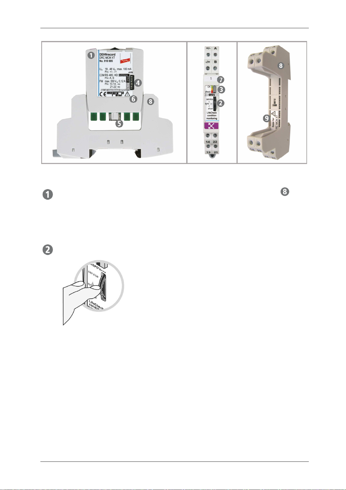
DEHNrecord DRC MCM XT stationary monitoring device consists of
-a special base part for DIN rail
mounting and wiring
-a BXT plug-in module including
the condition monitoring unit
Apart from a quick guide
1)
, delivery includes the
BS BA1 BA15 BXT labelling system.
The current version of
-detailed instructions for use concerning DRC MCM XT (Publication No. 1669)
-the DRC MCM XT device software
-an installation packet for the PC software Status Display + Service Console for
visualising and accessing the device via RS485 interface including operating
manual
/3/
-an installation packet for the Software DRC SW Update PC software for updating
the DRC LC M3+ reader and DRC MCM XT monitoring device via interface
including operating manual
/2/
-an operating manual for hand-held reader DRC LC M3+
/1/
-a device software for hand-held reader DRC LC M3+
/1/
can be downloaded from www.dehn.de/download/ or can be ordered as CD-ROM
version for a nominal fee.
1) Publication No. 1666, see also www.dehn.de
DEHN + SÖHNE Operating manual DEHNrecord DRC MCM XT
protected by ISO 16016 Page 7 of 49 Date of issue: 08.03.10
DRC MCM XT plug-in module for plugging/snapping into the base part ;
Monitoring device for stationary permanent LifeCheck
®
of up to 10
BLITZDUCTOR
®
XT (or CT) modules.
3-way button for controlling DRC MCM XT with the following functions:
service activates and/or deactivates the Service mode
(extended interface functions)
sync changes from Slave mode to Master mode
and back again, i.e. it starts and/or stops the
monitoring process, which also includes the
synchronisation of several devices connected
with each other via the bus
show starts and/or cycles the detailed LED
operating state indication
The button is to be operated by pressing (sync)or by switching it without
pressure up (service)or down (show).
The button has to be applied for min. 2 seconds or until the corresponding
function can be read from the LED indication.
During the test procedure (LED, permanent orange light) no application of the
button will be accepted.
Checking (LED, permanent orange light) can be
interrupted by any button actuation, see also "Added/new functions for the DRC
MCM XT" in chapter 13.
DEHN + SÖHNE Operating manual DEHNrecord DRC MCM XT
protected by ISO 16016 Page 8 of 49 Date of issue: 08.03.10
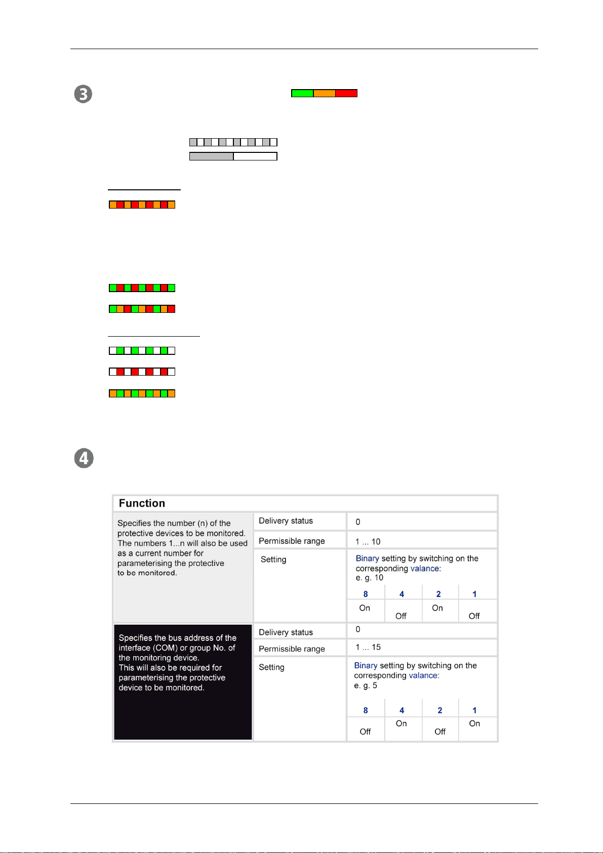
Indicator element (3-colour LED) for indicating the monitoring and
device status. The blinking LED indicates the operating state.
Irrespective of the colour,
- fast blinking stands for device in Master mode
- slow blinking stands for device in Slave mode
Device status, irrespective of the blinking frequency, means
Starting sequence: - Master is checking for other master at the
bus
- Slave is waiting for synchronisation by
master.
Service mode: Access to service information via bus
Device status, failure/ wrong configuration (DIP switch)
Monitoring status, irrespective of the blinking frequency,
means that all monitored protective devices are alright
means that at least 1 of the monitored SPDs has to be replaced
means that status "Replace SPD“ was acknowledged for remote
signalling contact.
8-way DIP switch for configuring the monitoring device, divided in 2 functional
groups;
Settings may only be performed after removing the plug-in unit.

DEHN + SÖHNE Operating manual DEHNrecord DRC MCM XT
protected by ISO 16016 Page 9 of 49 Date of issue: 08.03.10
Slider switch/jumper for activating (On) and/or deactivating (Off) the 120 Ω
termination impedance (R
T
) at the connections (A and B) of the serial 2-wire
RS485 interface (COM) during half-duplex operation (HD).
Configuration by slider switch:
R
T
deactivated R
T
activated
(as-delivered state)
Configuration by jumper:
R
T
deactivated R
T
activated
(as-delivered state)
Switching/jumping may only be done after removing the plug-in unit.
Warning, observe installation instructions!
Adhesive label of the labelling system included in delivery, for marking
DRC MCM XT with the bus address (BA1...BA15) set at the DIP switch. This
bus address or group No. is required for programming the protective devices for
stationary monitoring and/or for localising faulty protective devices and
providing replacement devices.

DEHN + SÖHNE Operating manual DEHNrecord DRC MCM XT
protected by ISO 16016 Page 10 of 49 Date of issue: 08.03.10
Special base part for DIN rail mounting with terminal screws, for supporting the
plug-in module
.
Warning: Base part designed for DRC MCM XT plug-in module only; observe
the installation instructions!

DEHN + SÖHNE Operating manual DEHNrecord DRC MCM XT
protected by ISO 16016 Page 11 of 49 Date of issue: 08.03.10
6. Design/Arrangement
With DRC MCM XT monitoring device, 1 to 10 BLITZDUCTOR
®
XT or CT modules
with LifeCheck
®
function can be permanently monitored.
Monitoring of BXT...EX...urgently requires the installation of separators TW DRC MCM
EX in order to have a separation distance between intrinsically safe and not
intrinsically safe circuits! The separator requires a space of min 14 cm (e.g. distance
to cable ducts at least 14 cm and DIN rail in centred arrangement to the cable ducts).
The protective devices should be assigned to the monitoring devices as equally as
possible. The DRC MCM XT device, however, has to be arranged as centrally as
possible between the assigned SPDs. Reserve slots shall be positioned on the outer
sides. In case of a mixed monitoring of BLITZDUCTOR
®
XT and CT modules, they
have to be arranged according type and each type on one side.
Potential sources of interference, e.g. switched-mode power supplies having a pulse
frequency similar to the RFID operational frequency, should be installed in the
minimum distance specified.
6.1 Single application
A minimum distance of 25 cm (radius) between the DRC MCM XT devices has to be
kept in order to exclude mutual interference and thus incorrect measurements.
Apart from the number of protective devices to be monitored, also the bus
address/group No. (any No., 1 ... 15) has to be set at each DRC MCM XT device.
Assigned protective devices have to be parameterised according to the bus address
set.
Apart from connecting the remote signalling contacts, the DRC MCM XT only needs
the d.c. supply voltage.
DEHN + SÖHNE Operating manual DEHNrecord DRC MCM XT
protected by ISO 16016 Page 12 of 49 Date of issue: 08.03.10
The termination impedance (R
T
) at the RS-485 interface should remain active or
should be activated for noise immunity.
2)
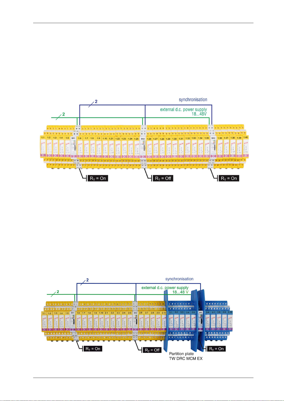
6.2 Multiple application
The minimum distance has not to be kept, if, apart from being connected to the
external d.c. power supply,the devices are additionally connected/synchronised in
parallel via interface (Pins A and B).
The individual DRC MCM XT devices have to be marked with different group Nos. and
the protective devices have to be parameterised accordingly.
At the start and end of the bus connection, the bus termination impedances remain
activated (On) per switch/jumper or have to be activated at the devices. At the devices
in between, they must be deactivated (Off).
2)
Monitoring of BXT...EX...arrester modules also here requires the application of
partitions to separate intrinsically safe and not safe circuits! The space requirement of
at least 14 cm (e.g. distance from cable ducts in case of centred arrangement of DIN
rail) has to be minded.
2) See 8.3 Interface termination impedance

DEHN + SÖHNE Operating manual DEHNrecord DRC MCM XT
protected by ISO 16016 Page 13 of 49 Date of issue: 08.03.10
7. Connections
Installation wiring at the base and removed plug-in module.
Illustration of remote signalling contacts: Functional principle! Contacts are integrated
in the monitoring module!
Note:
Conductors of intrinsically safe and non-intrinsically safe circuits which are routed in
same conductor bundle or cable duct, have to be isolated by means of an insulating
layer or an earthed metal intermediate layer in accordance with EN 60079-14.
Isolation is not required if coated or shielded conductors are used in intrinsically safe
or non-intrinsically safe circuits.
7.1 Power supply
The d.c. power supply of the device has to be provided via +/- and -/+ terminals.
Polarity: optional
Nominal voltage (range): 24 (18...48) V
d.c.
Max. current input: 80 (100...60) mA
Smoothing and residual ripple of the power supply have to be within the nominal
voltage range!
If a totally insulated power supply unit is used ( ), the termination impedance (R
T
)
of the RS-485 interface has to be activated (On) for single application!
2)
7.2 Remote signalling contacts
Remote signalling of the monitoring status of each group can be effected via
electrically isolated break and make contacts integrated into the DRC MCM XT device.
A collective signal for the complete assembly will not be generated, if several devices
are synchronised.
Thus, either a linked or separate (for potential different priorities) remote signal can be
sent to a superordinated control level.
Without power supply, the remote signalling contacts change to “Replace SPD” status
until the next LifeCheck
®
is performed. The “Replace SPD” status can be quit via the
extended functions of the DRC MCM XT. See also Chapter 13.
2) See 8.3 Interface termination impedance

DEHN + SÖHNE Operating manual DEHNrecord DRC MCM XT
protected by ISO 16016 Page 14 of 49 Date of issue: 08.03.10
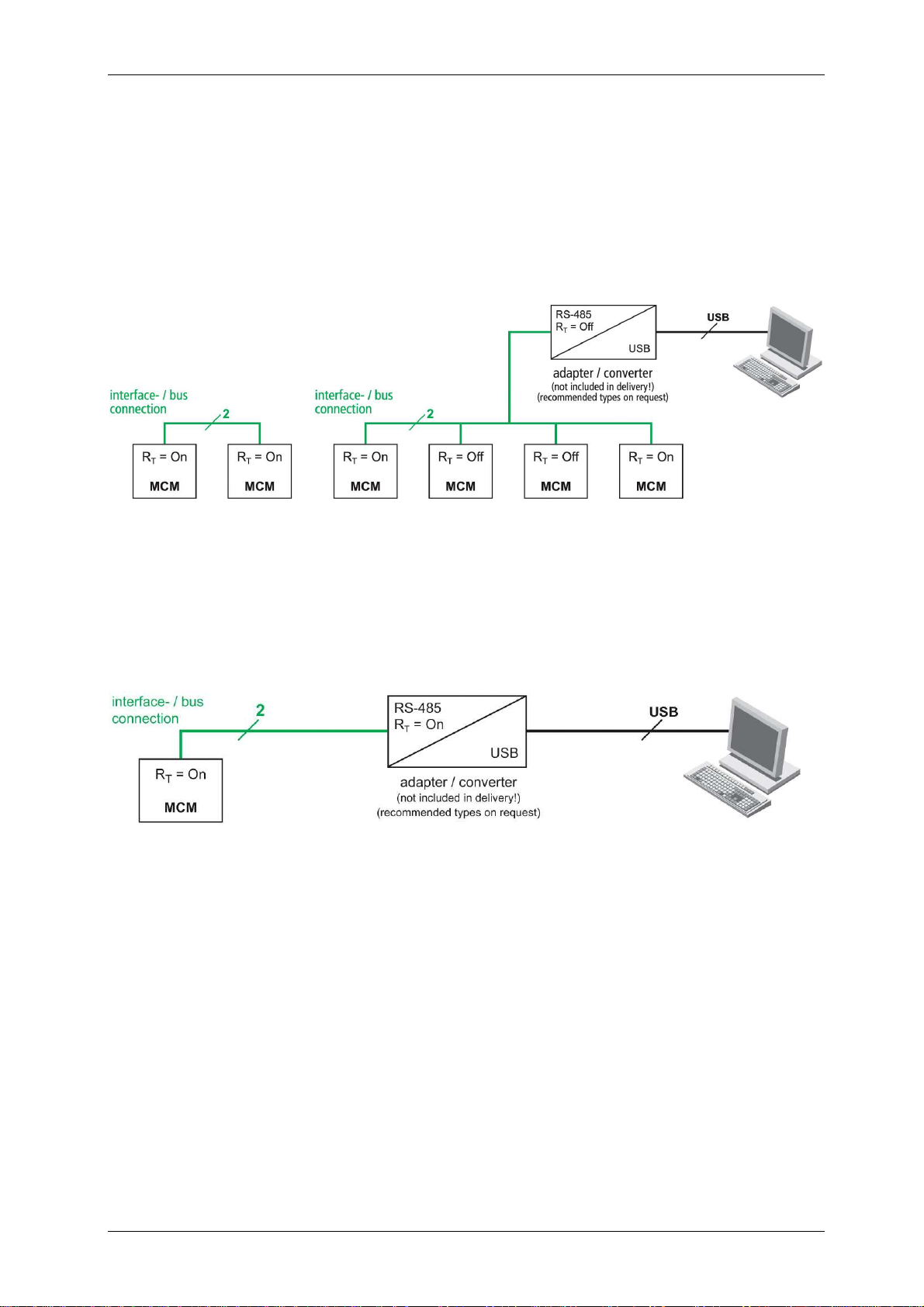
7.3 RS485 Bus interface
The bus is connected to the device and/or between several devices via the Aand B
terminals.
The individual devices have then to be connected with each other in parallel (A to A
and B to B).
A twisted two-wire line is generally recommended as bus connection. A shielded type
should be used for cables longer than 3 m and for lengths up to 1.2 km, both the surge
impedance of 120 Ωand a conductor cross-section of >0.5 mm² has to be considered.
Conductors crossing between buildings also require a separate surge protection.
The state of the termination impedance (R
T
activated or deactivated) has to be
observed!
2)
2) See 8.3 Interface termination impedance

DEHN + SÖHNE Operating manual DEHNrecord DRC MCM XT
protected by ISO 16016 Page 15 of 49 Date of issue: 08.03.10
8. Configuration
Settings/Modifications of the device configuration can/must only be implemented at
the removed plug-in unit.
When delivered, all DIP switches are set to OFF. When starting operation, this causes
a fault indication (inadmissible configuration).
8.1 Number of protective devices to be monitored
The number of protective devices to be monitored by the device has to be set via 4
DIP switches on the side. Settings to 0 or > 10 lead to a fault indication via LED when
starting operation.
8.2 Bus address/Group No.
The bus address of the serial RS485 interface integrated into the device, which is also
set by 4 DIP switches on the side, will be used at the same time as a group No. for the
protective devices assigned. If 0 is set, a fault is indicated via LED when starting
operation.
For synchronising several devices, these have to be configured with different bus
addresses, which have to correspond to the programming of the SPDs assigned.
DEHN + SÖHNE Operating manual DEHNrecord DRC MCM XT
protected by ISO 16016 Page 16 of 49 Date of issue: 08.03.10
8.3 Interface termination impedance
The device has a serial RS485 interface for half-duplex operation (HD, 2-wire
connection). In order to ensure a safe data transmission on this differential bus, it is
necessary to activate a 120 Ωtermination impedance (R
T
) at each of the both terminal
points of the bus system within the devices.
It is advisable to activate the termination impedance of DRC MCM XT even for a
single application due to interference immunity (e.g. if a totally insulated power supply
unit is used) and to ensure that the module does not have to be removed in case of
extension or access by PC for maintenance purposes and/or to ensure that there are
no transmission problems.

DEHN + SÖHNE Operating manual DEHNrecord DRC MCM XT
protected by ISO 16016 Page 17 of 49 Date of issue: 08.03.10
The termination impedance (R
T
) can be activated and/or deactivated on the bottom
side of the plug-in module after removing it by positioning the slider switch/jumper.
The corresponding position can also be taken from the rating plate.
The position can usually be set by means of tweezers.
In as-delivered state, the termination impedance is activated.
Configuration by slider switch:
R
T
deactivated R
T
activated
Configuration by jumper:
R
T
deactivated R
T
activated

DEHN + SÖHNE Operating manual DEHNrecord DRC MCM XT
protected by ISO 16016 Page 18 of 49 Date of issue: 08.03.10
9. Programming the protective devices
In as-delivered state, Blitzductors
®
XT and CT cannot be used with a DRC MCM XT at
the same time yet. The protective devices can be assigned to the respective
DRC MCM XT monitoring device only by correspondingly programming of the RFID
transponders which are integrated into the protective devices.
When programming the protective devices, a definite password for each transponder
is generated and stored in the transponder, containing the bus address/group No. of
the assigned monitoring device as well as current number of the respective
Blitzductor
®
within the group.
During operation, the transponder then reacts only upon enquiries containing its
password.
There are three possibilities for programming the devices:
-Online programming via PC and DRC MCM XT monitoring device
-Offline programming via DRC LC M3+ reading device
-Direct programming at the DRC MCM XT monitoring device (see extended
functions in Chapter 13)
9.1 Online programming by PC and DRC MCM XT monitoring device
Conditions:
A PC with connected and installed USB/RS485 converter is connected to
DRC MCM XT via interface (observe configuration of the termination impedances (R
T
)
of the bus!).
2)
All DRC MCM XT devices connected to the bus are set to slave mode
(eeeeeeeeeeee slow blinking).
The DRC MCM XT device to be used for programming, has to be set to service mode
to ensure that it can be addressed by the software
/3/
.
Unprogrammed SPDs must not be within the range of DRC MCM XT. The figure
shows the initial situation for installation.
2) See 8.3 Interface termination impedance

DEHN + SÖHNE Operating manual DEHNrecord DRC MCM XT
protected by ISO 16016 Page 19 of 49 Date of issue: 08.03.10
On the PC the service function Service Console is started in the Status Display +
Service Console software and the bus address corresponding to the DRC MCM XT
device is set.
3)
Important:
-Make sure that only 1 unprogrammed SPD is situated within the range (25 cm) of
the DRC MCM XT device to be used for programming!
-Program the respective SPD only at its final plug-in position!
-Do not click in the SPD to be programmed but plug it in only to the first mech.
resistance!
-Label the programmed SPDs immediately! By using only their current numbers (1,
2, ..., 9, 10) or, even better, by using them in connection with the group No. of the
DRC MCM XT device (if the group No. is BA 3, for example, then use 3.1, ... 3.9,
3.10)! And/or note down the individual passwords in the documentation!
-Click in the programmed SPDs completely!
-The command "program all SPDs of a DRC MCM XT" allows the user to carry out
the programming procedure shown in the following step by step. Instruction for
further proceeding will be displayed.
3)
3) See also operating manual for Status Display + Service Console /3/.

DEHN + SÖHNE Operating manual DEHNrecord DRC MCM XT
protected by ISO 16016 Page 20 of 49 Date of issue: 08.03.10
Procedure:
Items 1–4 have to be performed one after another and for each individual SPD to be
programmed!
1.
Insert the SPD to be programmed into its
plug-in position, but do not click it in!
For installation, proceed from the left to the right
For service purposes, proceed directly at the
plug-in position.
2. In the service function Service Console, select
the “Program individual SPD for DRC MCM
XT” command and enter the corresponding
current SPD No..
Select command (#1), then the SPD No. (#2)
and Send command (#3).
The programming result will be indicated by
the result display of the Service Console.
3)
If the programming fails repeatedly, the status
of the SPD has to be checked with
DRC LC M3+ reading device.
3. Label the successfully programmed SPD.
4. Click in the SPD completely.
#3
#1 #2
Table of contents
Other DEHN + SÖHNE Measuring Instrument manuals


