Dehutech DT-3500 User manual


© 2016 DehuTech AB - Subject to change without notice DT-3500 - 2
EC-declaration of conformity
Dehutech AB
Mätslingan 22
SE-187 66 TÄBY
Sweden
declare under own responsibility that the product:
Dehumidifier DehuTech 3500 (type DA-3500 in Swedish market) from unit no 141 1601
which is detailed in this declaration complies to the following harmonized European standards and
technical specifications:
SS-EN 60335-1/A13 Electrical domestic appliances - general requirements
SS-EN 60335-2-40 issue 4.2 Specified requirements for electrical heat pumps, air
conditioning units and dehumidifiers.
SS-EN 60335-2-40 C1 Specified requirements for electrical heat pumps, air
conditioning units and dehumidifiers.
amendments SS-EN 60335-1 T1:2, T2, T3, T4, T5
according to conditions in directive:
2006/95/EC Low voltage directive
2004/108/EC EMC Directive (Standard units)
Täby 2016-01-04
________________________
Ulf Rahle, Managing Director

© 2016 DehuTech AB - Subject to change without notice DT-3500 - 3
Table of contents
GENERAL SAFETY INFORMATION......................................................................................................................................4
APPLICATIONS ..................................................................................................................................................................5
METHOD OF OPERATION ..................................................................................................................................................5
PRODUCT DESCRIPTION....................................................................................................................................................6
CASING ...................................................................................................................................................................................6
ROTOR ....................................................................................................................................................................................6
FILTERS ...................................................................................................................................................................................6
FANS FOR PROCESS-AND REACTIVATION AIR ...................................................................................................................................6
HEATER FOR REACTIVATION AIR....................................................................................................................................................6
ELECTRICAL PANEL .....................................................................................................................................................................6
OPERATION OPTIONS .................................................................................................................................................................6
INSTALLATION ..................................................................................................................................................................7
INSTALLATION AND SERVICE ACCESS...............................................................................................................................................7
DUCT CONNECTION FOR PERMANENT INSTALLATION.........................................................................................................................7
ELECTRICAL INSTALLATION...........................................................................................................................................................7
COMMISSIONING .............................................................................................................................................................8
MAINTENANCE .................................................................................................................................................................9
FILTERS ...................................................................................................................................................................................9
ROTOR ....................................................................................................................................................................................9
ELECTRICAL MOTORS..................................................................................................................................................................9
HEATER ...................................................................................................................................................................................9
ROTOR DRIVE BELT.....................................................................................................................................................................9
ROTOR SEALINGS.......................................................................................................................................................................9
GENERAL SUMMARY OF MAINTENANCE INTERVALS.........................................................................................................................10
TRANSPORTATION.......................................................................................................................................................... 10
FAULT FINDING...............................................................................................................................................................11
TECHNICAL DATA............................................................................................................................................................ 12
DIMENSIONS ..........................................................................................................................................................................12
TECHNICAL DATA.....................................................................................................................................................................12
PERFORMANCE CHART &DRY AIR FLOW DIAGRAM .........................................................................................................................13
SPARE PARTS LIST...........................................................................................................................................................13
COMPONENT DATA ........................................................................................................................................................15
MISCELLANEOUS / NOTES...............................................................................................................................................17
APPENDIX 1 – ELECTRICAL WIRING ................................................................................................................................. 18

© 2016 DehuTech AB - Subject to change without notice DT-3500 - 4
General safety information
•Anyone operating the DehuTech
dehumidifier should have access to this
manual, and should be aware of the safety
information.
•Only personnel with adequate knowledge
of the dehumidifier should be allowed to
operate and service it.
•Only personnel with authorization for
electrical installations are allowed to make
repair of electrical components.
•Repair of electrical components should be
carried out by suitable qualified
personnel.
•The dehumidifier must not be installed in
areas where explosion proof equipment is
required.
•Disconnect the dehumidifier from the
mains prior to opening any service panel.
•Prior to servicing the dehumidifier must
be left to cool down for at least 15
minutes after operation.
•The service panel should remain closed
except when servicing is carried out.
•The dehumidifier can only be used for
dehumidification of air at atmospheric
pressure.
•Never use the dehumidifier without the
filters as the desiccant rotor can become
contaminated and lose capacity.
•Signs and instructions on the dehumidifier
should not be removed or altered.
•This manual should always be accessible
and kept close to the dehumidifier.
•All maintenance and control of the
dehumidifier should be as per the
specified schedule.
•Use only genuine spare parts.
•Written permission must be obtained from
DehuTech AB prior to making any alteration
or modification.

© 2016 DehuTech AB - Subject to change without notice DT-3500 - 5
Applications
The DehuTech Dehumidifier is of the solid
desiccant wheel type designed to dry air of
atmospheric pressure. The dehumidifier can be
used for drying air of up to 100 % relative
humidity (RH) with temperatures from -30°C to
+40°C.
The applications are numerous and wide
spread. Below are some examples:
•Controlling humidity levels in production
processes.
•Drying of temperature sensitive products.
•Maintaining correct humidity in storage
areas.
•Protection of equipment sensitive to
corrosion.
•Controlling humidity levels in museums
and archives.
•Drying after water damage and drying of
buildings during construction.
•Climatic improvements in damp areas.
Method of operation
The dehumidifier operates with two air
streams. A larger air stream to be dehumidified,
and a smaller air stream to exhaust the
moisture out of the desiccant rotor.
Two fans inside the dehumidifier create air
streams which travel through the desiccant
rotor in opposite directions.
The larger air volume, the process air, passes
through the slowly rotating silica gel rotor.
Silica gel is a hygroscopic material adsorbing
water vapour direct from the air. When passing
through the rotor the humidity of the air is
reduced, whilst the moisture content of the
rotor material increases. On exiting the rotor
the dried air is introduced into the area, or the
process to be dehumidified. The adsorption
process works in temperatures from -30°C to
+40°C.
The smaller air volume, the reactivation air,
adsorbs the moisture from the silica gel rotor.
This reactivation air is heated by an internal
heater to a temperature of approximately
+120°C. As the reactivation air passes through
the rotor, in an opposite direction to the dry air,
it will decrease the moisture content of the
rotor material. The reactivation air will leave
the dehumidifier as warm, moist air, which is
then exhausted out from the building.

© 2016 DehuTech AB - Subject to change without notice DT-3500 - 6
Product description
The dehumidifier is designed to meet the
requirements of IEC protective class IP 44.
Casing
The casing is fabricated from stainless steel and
is insulated including inner panels. The top of
the dehumidifier has a panel that can be
removed for service access. All duct
connections to the dehumidifier are designed
for connections to standard size spiral ducts.
Rotor
The dehumidifier has a drying rotor fabricated
from a desiccant material. The rotor has a
matrix of corrugated and flat heat resistant
sheets which houses the Silica Gel desiccant
agent. This matrix creates a large number of
axial flutes through the rotor, which together
builds up an immense surface area for moisture
adsorption in a small volume. The rotor is
manufactured and processed to be able to
withstand moisture saturated air without being
damaged. This means the rotor can be used in
conjunction with a pre- cooling coil.
Furthermore the rotor will not be damaged
even if the fan or the heater for reactivation
should fail during operation. The rotor is
incombustible and non-flammable.
Rotor sealings
The rotor has two pheriperical sealings.
Rotor drive system
The slow rotation of the rotor is achieved by an
electrical gear motor and a belt drive. The belt
sits on the outer rim of the rotor and is driven
by a pulley on the drive motor. A belt tension
device keeps the belt in place and maintains
tension to prevent belt slip. Correct operation
of the drive system, and direction of rotation
can be checked by opening the front panel.
The centre hub of the rotor is equipped with
ball bearings. The rotor shaft is made from
stainless steel.
Filters
The dehumidifier has two separate filters. One
in the process air inlet and one in the
reactivation air inlet.
Fans for process- and reactivation air
The fans are direct driven radial fans with a
three phase EC motor for the process air fan
and a single phase EC motor for the
reactivation air fan, class IP 54, ISO F. The fans
are accessible for service behind the panels.
Heater for reactivation air
The reactivation heater is of the PTC-type
(Positive Temperature Control), which cannot
be overheated, and gives the possibility of a
stepless control for 50 - 100 % of the
dehumidification capacity. This is achieved by
controlling the reactivation air volume.
Electrical panel
The electrical panel is located in a separate
compartment at the top of the dehumidifier.
Switches and indications for operation are
mounted at the front of the dehumidifier.
Operation options
Using the operation switch on the dehumidifier,
different running options can be selected:
0 Dehumidifier not in operation.
MAN Dehumidifier in continuous
operation.
AUTO Automatic operation by remote
humidistat, or other external
start/stop signal.
In the electrical compartment, there is a switch
marked S3, which allows continuous operation
of the dry air fan.
For dehumidifiers with PLC, the operation
is described in the PLC controller manual.

© 2016 DehuTech AB - Subject to change without notice DT-3500 - 7
Installation
Installation and service access
The DehuTech Dehumidifier is designed for
indoor installation, and must be installed in an
upright position, preferably bolted to the floor.
Ensure a space of 1000 mm above the
dehumidifier for inspection and service.
Duct connection for permanent installation
The dehumidifier can be installed in the room
that should to be dehumidified or in a separate
room.
To obtain the best performance the outlets from
the fans should be equipped with diffusors.
Wet air duct out from dehumidifier
The wet air from the dehumidifier should be
exhausted to the outside. The duct should be as
short as possible to minimize the chance of
condensation of the wet air. This duct should
slope down slightly to stop any condensed water
from flowing back into the dehumidifier.
If the wet air duct is extremely long, or must be
installed sloping upwards from the dehumidifier,
it should be insulated and have a drainage point
(2-4 mm) drilled at its lowest position.
The exhaust opening should have a coarse wire
net.
Reactivation air into the dehumidifier
The reactivation air duct into the dehumidifier
should be as short as possible. The intake
opening of the duct should have a coarse wire
net, to stop foreign objects from entering the
dehumidifier. No insulation is needed and the
duct can slope up- or downwards. In some
installations, as an alternative, the reactivation
air can be taken from the installation room. For
this alternative no duct connection is needed.
A damper should be installed in the reactivation
air duct to enable correct setting of the
reactivation air volume during commissioning.
Process- and dry air with the dehumidifier
installed in the dehumidified room
When the dehumidifier is installed in the
dehumidified room space it would normally
take the process air direct from the room
without any duct system, with only a protection
net for the inlet required. The dry air outlet
would normally have a duct system designed
for distribution of the dry air in the building.
Process- and dry air with the dehumidifier
installed outside the dehumidified room
When the dehumidifier is installed in a separate
plant room all inlet and outlet openings are
usually ducted.
The dehumidifier takes the process air as
ambient air, or as pre-treated air
(cooled/heated), or alternatively as return air
from the dehumidified room. The dry air from
the dehumidifier can be connected for post
treatment or ducted back to the dehumidified
room.
A damper can be installed in the process air duct,
enabling correct commissioning of the dry air
volume.
Electrical installation
See the electrical wiring diagram in appendix 1.

© 2016 DehuTech AB - Subject to change without notice DT-3500 - 8
Commissioning
On initial start-up, the following steps should be
taken in this order:
1. Ensure that the external isolation switch
is isolating the unit from the mains, and
that the main switch on the
dehumidifier is set in the OFF position.
2. Open the service panel of the
dehumidifier and ensure that no foreign
objects are left inside the unit or in the
electrical compartment
3. Ensure that the process and reactivation
air dampers are open, and that ducts are
clean and free of blockages.
4. Check that air filters are installed and
clean.
5. Rotate the fan impellers by hand and
make sure they can move freely.
6. Ensure that the mains supply fuse is
suitably rated.
7. Compare set values for motor circuit
breakers with correct values in electrical
wiring diagram in appendix 1.
8. Connect the dehumidifier to the main
electrical supply by turning the isolation
switch to ON, and check all three phases
are live. Terminal L1, L2, L3 in the
dehumidifier.
9. Check to see that the lamp called STAND
BY is lighting up, but that the machine
doesn’t start.
10. Start the dehumidifier for a short
moment (3-4 seconds) by turning the
main switch to the MAN position. While
in operation, check that the rotor is
slowly turning in the right direction, and
the green operation lamp lights up.
Stop the dehumidifier by turning the
main switch to 0, and check the
direction of rotation for the fans.
11. Mount the service panels and ensure
they seal properly to the casing.
12. The dehumidifier is now ready for
operation.
13. Start the dehumidifier and check that
the unit is operating at the correct air
volumes by taking measurements in the
ducts. Always check the airflows on the
overpressure side of the dehumidifier
(dry air duct and wet air duct).
14. If requested check the dehumidification
performance by measuring humidity in
the dry air outlet from the dehumidifier.
Compare the result with the
performance chart on page 13.

© 2016 DehuTech AB - Subject to change without notice DT-3500 - 9
Maintenance
NOTE! With all maintenance and service of the
dehumidifier:
•Switch off the dehumidifier
approximately 15 minutes prior to
opening any service panel, allowing the
heater to cool down.
•Disconnect the dehumidifier from main
electrical supply by turning the external
switch to the off position.
The maintenance intervals for the dehumidifier
depend on the surrounding environment and
installation site. Recommended maintenance
intervals could therefore differ from one
installation to another. Incorrect maintenance
and service may result in reduced
dehumidification capacity.
Filters
The dehumidifier is equipped with two separate
filter banks, one for the process air and the other
for the reactivation air. The filters are positioned
at the respective inlets and will clean the air prior
to entering the dehumidifier.
Intervals for cleaning or replacement of the
filters will be determined by the amount of dust
and particles in the air at the installation site.
We recommend that the filters are checked at
least once a month.
The unit can be equipped with differential
pressure measurement for checking the
pressure drop over the filters.
Never operate the dehumidifier without the
filters, as the rotor can be damaged by dust.
Rotor
The rotor is maintenance free. However should
it be necessary to clean the rotor the first choice
should be careful use of compressed air. With
severe contamination the rotor can be washed
with water.
Cleaning with water is no routine matter, please
contact DehuTech AB or local distributor prior to
this procedure.
Check the rotor bearing and the rotor surface
once a year.
Electrical motors
The electrical motors are equipped with ball
bearings. The bearings are designed to last
the life of the motor and therefore no
maintenance is required.
Check the motors once a year for any
abnormal sound.
Heater
The reactivation electric heater does not need
maintenance, but should be checked twice a
year for any mechanical damage to the heating
elements.
Rotor drive belt
Check the belt tensioning at regular
intervals. The tensioning is maintained
constantly by the belt tension device, and
should not need to be adjusted during
normal operation.
Rotor sealings
Check that the sealings are in the right
position and not damage.

© 2016 DehuTech AB - Subject to change without notice DT-3500 - 10
General summary of maintenance intervals
Filter
Rotor bearing
Motors
Rotor drive
Heater
Sealings
On demand
√
Every 6th month
√
√
√
Every 12
th
month
√
√
Transportation
Observe the following for transport or
handling of the dehumidifier:
•Check the dehumidifier on
delivery for any transport damage.
•The dehumidifier should be
protected from rain and snow.
•The dehumidifier should always
stand upright on its feet.
•Never put other goods on top of
the dehumidifier.
•Transport and lift the dehumidifier
by fork lift. Ensure that the forks
go all the way to the back of the
dehumidifier before lifting.

© 2016 DehuTech AB - Subject to change without notice DT-3500 - 11
Fault finding
Malfunction
Possible cause of trouble
Corrective action
None, or reduced
dehumidification capacity
Filter clogged
Electrical heater faulty
Airflow reduced
No rotation of rotor
Internal leakage in unit
Altered air volumes
Altered reactivation temperature
Air leakage
Clean or replace filters
Check fuses
Check openings and dampers
Check belt tensioning
Check sealings and springs
Measure and check air volumes
Check reactivation heater
Check panels and check seals
Circuit breaker or fuse faulty
Fan faulty
Too large air volume
Rotor does not rotate
Reactivation heater faulty
Check fans and motors
Check air volumes and dampers
Check drive motor and drive belt
Check reactivation heater
Dehumidifier does not start
No control circuit
Faulty control signal
Phase fault
Fuse for controls faulty
Check control fuses
Check external start/stop signal
Check main fuses and phase sequence
Check electrical components
Rotor does not rotate
Drive belt is slipping
Drive belt broken or worn
Rotor jammed
Drive motor faulty
Check belt tensioning
Replace drive belt
Check centre shaft, rim of rotor
Replace complete gear motor
No dry- or wet air volume
Filter clogged
Fan faulty
Phase fault
Ducts blocked
Clean or replace filters
Check fan, motor and impeller
Check main fuses and phase sequence
Check dampers and ducts

© 2016 DehuTech AB - Subject to change without notice DT-3500 - 12
Technical data
Dimensions
Technical data
Dehumidification capacity 19,2 kg/h (at +20°C and 60 % RH
See performance chart for other data)
Process air flow 3 500 m3/h (at 170 Pa available pressure)
Wet air flow 850 m3/h (at 260 Pa available pressure)
Power supply 28,7 kW (3 x 400 V, 50 Hz)
Weight 210 kg
Noise level 71 dB(A)
Note: Valid only for standard units, with standard air-flows.

© 2016 DehuTech AB - Subject to change without notice DT-3500 - 13
Performance chart & dry air flow diagram
© 2016 DehuTech AB - Subject to change without notice DT-3500 - 14
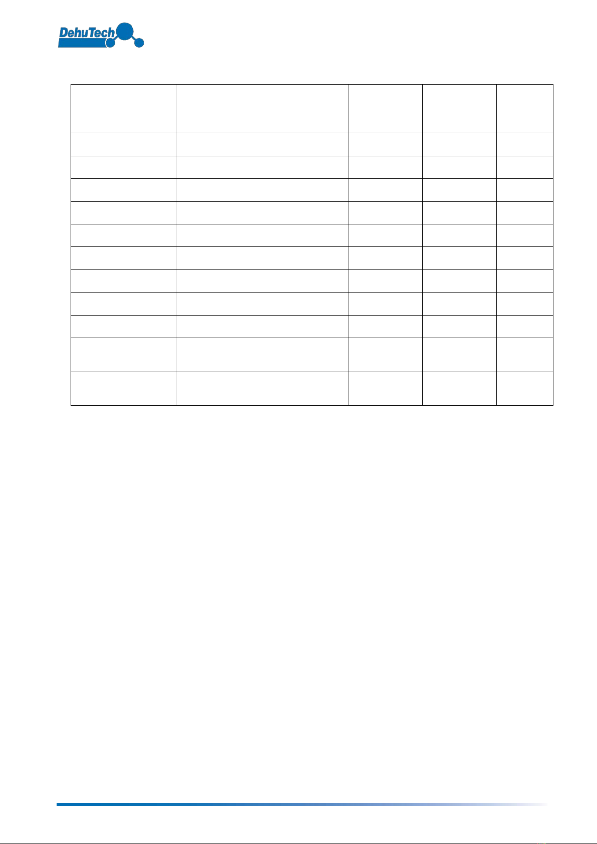
Spare parts list
Part
Technical specification
No installed
No of
recommended
spare parts
Comment
Drive motor
SMG65/30-4, 230-240V 50Hz 3 rpm
1
1
Capacitor
0,5 µF 700 V
1
Belt pulley
12 L 050-6F
1
Drive belt
855 L ( width 12 mm)
1
Belt tensioner
Rosta SE11 + R11
1
Process air fan
GR31C-ZID.DC.1K (400V)
1
React. air fan
K3G 250-RR01-H2 (230V)
1
Heater PTC
HRKK 42/22 - 400V
1
1
Rotor
Rotor 3500
1
Process air filter
Panel filter
715 x 494 x 45 mm
1
2
Reactivation air filter
Panel filter
310 x 450 x 25 mm
1
2
© 2016 DehuTech AB - Subject to change without notice DT-3500 - 15
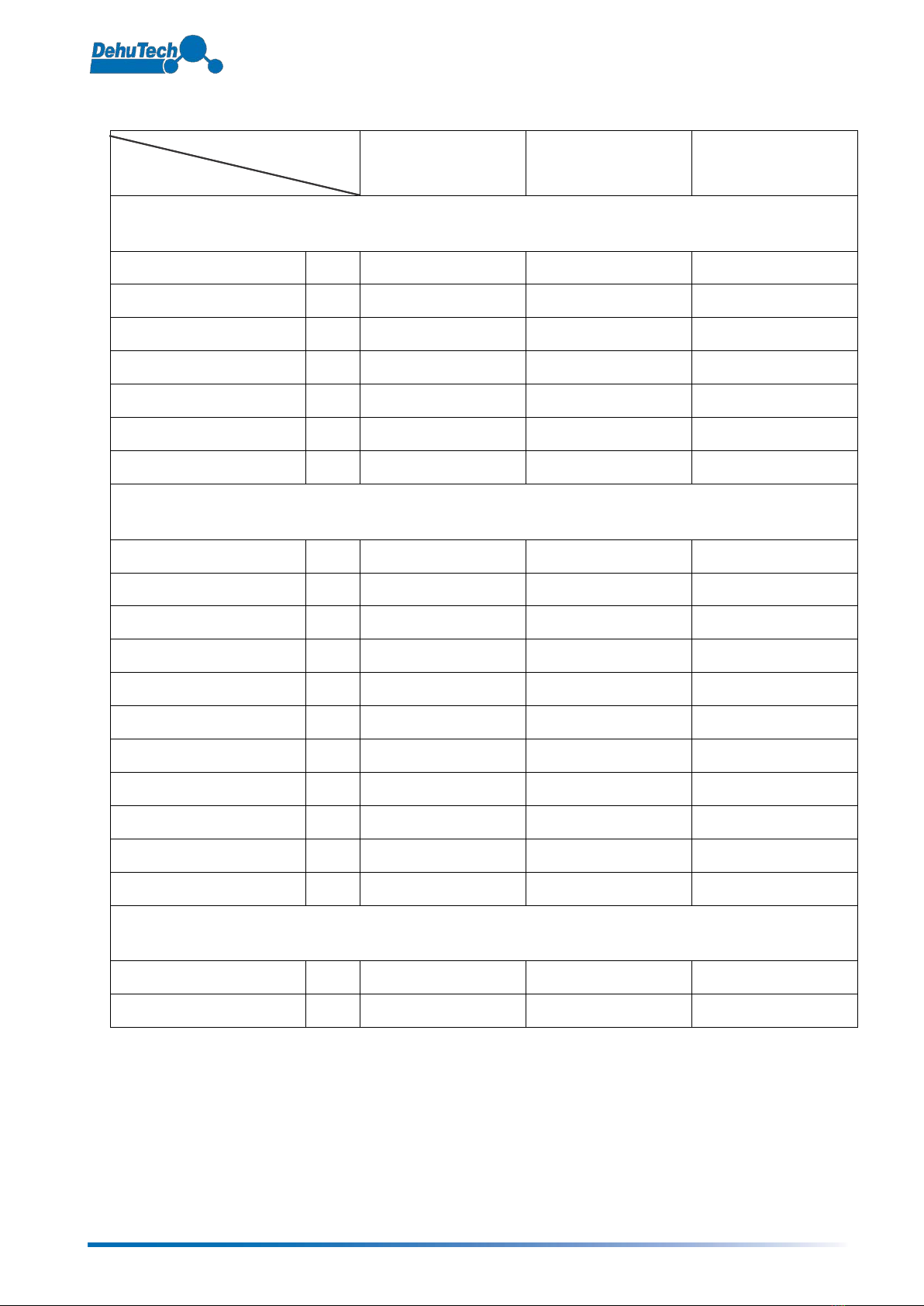
Component data
Unit part:
Components:
Process air side
(Dry air side)
Reactivation air side
(Wet air side)
Rotor
FANS
Manufacturer
ZIEHL-ABEGG
ebmpapst
Fan type
GR31C-ZID-DC.1K
K3G 250-RR01-H2
Speed
rpm
3 550
3 740
Model
RH31C-ZID.DC.1R
R3G 250-RR01-H1
Air flow
m3/h
3 500
850
Head pressure
Pa
External pressure available
Pa
170
260
MOTORS
Manufacturer
ZIEHL-ABEGG
ebmpapst
Rotek
Model
-
M3G 084-DF
SGM65/30-4
Speed
rpm
3 550
3 740
3,0
Power
kW
2,2
0,5
7,8 W
Voltage
V
3 x 400
230
230
Frequency
Hz
50/60
50/60
50/60
Amps
A
3,6
2,2
60 mA
Power factor
cos
ϕ
-
-
Protection class
IP
54
54
Insulation class
ISO
F
F
Specialties
ROTOR
Type
Rotor 3500
Rotor speed
rph
11
Continued on next page.
© 2016 DehuTech AB - Subject to change without notice DT-3500 - 16
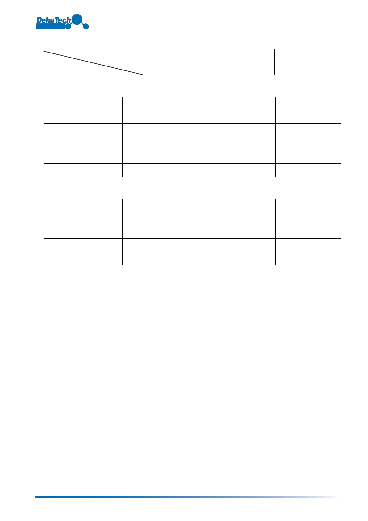
Continued from previous page.
Unit part:
Components:
Process air side
(Dry air side)
Reactivation air
(Wet air side)
Rotor
FILTERS
Type
Panel filter
Panel filter
Filter class
EU-4
EU-4
Filter media
Glass fibre
Glass fibre
Dimensions
mm
1p. 715 x 494 x 45
1p. 310 x 450 x 25
Pressure drop, clean filter
Pa
40
40
Pressure drop, dirty filter
Pa
140
140
HEATER, REACTIVATION AIR
Power
kW
24
Type
PTC
Voltage
V
400
Number of elements
Type of elements
Resistance PTC

© 2016 DehuTech AB - Subject to change without notice DT-3500 - 17
Miscellaneous / Notes
DehuTech AB
Mätslingan 22
SE-187 66 TÄBY
Sweden
Tel: +46 8 792 04 08
Fax: +46 8 792 55 59
E-mail: info@dehutech.com
Website: www.dehutech.com

© 2016 DehuTech AB - Subject to change without notice DT-3500 - 18
Appendix 1 – Electrical wiring
Table of contents
Other Dehutech Dehumidifier manuals


Popular Dehumidifier manuals by other brands

Seaira Global
Seaira Global WatchDog NXT60 How to Change the Control Board

KUL
KUL KU34393 user manual

Ingersoll-Rand
Ingersoll-Rand HRD Series Operator's instruction manual

Breville
Breville All Climate LAD250 Instruction book

Sinclair
Sinclair CFO-20N Service manual

Meritor Wabco
Meritor Wabco System Saver Series Maintenance manual


