Meritor Wabco System Saver Series User manual

Service Notes
1
Service Notes
Before You Begin
This manual provides instructions for Meritor
WABCO’s System Saver Series single cartridge air
dryers. Before you begin procedures:
1. Read and understand all instructions and
procedures before you begin to service
components.
2. Read and observe all Caution and Warning
safety alerts that precede instructions or
procedures you will perform. These alerts help
to avoid damage to components, serious
personal injury, or both.
3. Follow your company’s maintenance and
service, installation, and diagnostics
guidelines.
4. Use special tools when required to help avoid
serious personal injury and damage to
components.
Safety Alerts, Torque Symbol
and Notes
Access Product and Service
Information on our Web Site
Enter meritorwabco.com in your browser’s
address box for quick access to our web site. At
our home page, click on literature to access our
publications.
meritorwabco.com
To Order Information by Phone
Call ArvinMeritor’s Customer Service Center at
800-535-5560 to order the following item.
O
Drivetrain Plus
TM
by ArvinMeritor Technical
Electronic Library on CD. Features product
and service information on most Meritor,
ZF Meritor and Meritor WABCO products.
$20. Order TP-9853.
WARNING
A Warning alerts you to an
instruction or procedure
that you must follow
exactly to avoid serious
personal injury.
CAUTION
A Caution alerts you to an
instruction or procedure
that you must follow
exactly to avoid damage to
components.
A torque symbol alerts you
to tighten fasteners to a
specified torque value.
NOTE
A Note provides
information or suggestions
that help you correctly
service a component.

Table of Contents
Section 1: Introduction
System Overview . . . . . . . . . . . . . . . . . . . . . . . . . . . . . . . . . . . . . . . . . . . . . . . . . . . . . . . . . . . . . . . . . . . . . .1
Air Dryer Documentation
Air Dryer Identification
How the Air Dryer Works . . . . . . . . . . . . . . . . . . . . . . . . . . . . . . . . . . . . . . . . . . . . . . . . . . . . . . . . . . . . . . .2
Air Dryer Cycle . . . . . . . . . . . . . . . . . . . . . . . . . . . . . . . . . . . . . . . . . . . . . . . . . . . . . . . . . . . . . . . . . . . . . . . .3
Air Dryer Components . . . . . . . . . . . . . . . . . . . . . . . . . . . . . . . . . . . . . . . . . . . . . . . . . . . . . . . . . . . . . . . . .4
Dryer Identification . . . . . . . . . . . . . . . . . . . . . . . . . . . . . . . . . . . . . . . . . . . . . . . . . . . . . . . . . . . . . . . . . . . .5
Description of Components
Section 2: Troubleshooting & Testing
Routine Maintenance . . . . . . . . . . . . . . . . . . . . . . . . . . . . . . . . . . . . . . . . . . . . . . . . . . . . . . . . . . . . . . . . . . .9
Maintenance Tips
Troubleshooting . . . . . . . . . . . . . . . . . . . . . . . . . . . . . . . . . . . . . . . . . . . . . . . . . . . . . . . . . . . . . . . . . . . . . .10
System Tests . . . . . . . . . . . . . . . . . . . . . . . . . . . . . . . . . . . . . . . . . . . . . . . . . . . . . . . . . . . . . . . . . . . . . . . .13
Heater Resistance
Leak Test
Air Pressure Checks
Operational Test for System Saver Series Air Dryers — Regeneration and Purge Style
Pressure-Controlled Check Valve Test — Regeneration Style Only . . . . . . . . . . . . . . . . . . . . . . . . . . . .14
Section 3: Installing Replacement Parts
Replacement Requirements . . . . . . . . . . . . . . . . . . . . . . . . . . . . . . . . . . . . . . . . . . . . . . . . . . . . . . . . . . . .15
Component Replacement . . . . . . . . . . . . . . . . . . . . . . . . . . . . . . . . . . . . . . . . . . . . . . . . . . . . . . . . . . . . . .16
Desiccant Cartridge
Outlet Check Valve Assembly . . . . . . . . . . . . . . . . . . . . . . . . . . . . . . . . . . . . . . . . . . . . . . . . . . . . . . . . . . .17
Heater Assembly
Turbo Cut-Off Valve Assembly . . . . . . . . . . . . . . . . . . . . . . . . . . . . . . . . . . . . . . . . . . . . . . . . . . . . . . . . . .18
Regeneration Valve Assembly . . . . . . . . . . . . . . . . . . . . . . . . . . . . . . . . . . . . . . . . . . . . . . . . . . . . . . . . . .19
Purge Valve Assembly . . . . . . . . . . . . . . . . . . . . . . . . . . . . . . . . . . . . . . . . . . . . . . . . . . . . . . . . . . . . . . . . .20
Pressure-Controlled Check Valve (PCCV) . . . . . . . . . . . . . . . . . . . . . . . . . . . . . . . . . . . . . . . . . . . . . . . . . .21
Bypass Valve
Pressure Relief Valve . . . . . . . . . . . . . . . . . . . . . . . . . . . . . . . . . . . . . . . . . . . . . . . . . . . . . . . . . . . . . . . . . .22
Purge Silencer (Muffler) . . . . . . . . . . . . . . . . . . . . . . . . . . . . . . . . . . . . . . . . . . . . . . . . . . . . . . . . . . . . . . .23
Air Dryer Assembly
Testing the Meritor WABCO System Saver Series Air Dryer . . . . . . . . . . . . . . . . . . . . . . . . . . . . . . . . . .24
Appendix I: Glossary
Basic Air System/Air Dryer Terms . . . . . . . . . . . . . . . . . . . . . . . . . . . . . . . . . . . . . . . . . . . . . . . . . . . . . . .25
Appendix II: Application Information
General Requirements . . . . . . . . . . . . . . . . . . . . . . . . . . . . . . . . . . . . . . . . . . . . . . . . . . . . . . . . . . . . . . . . .26
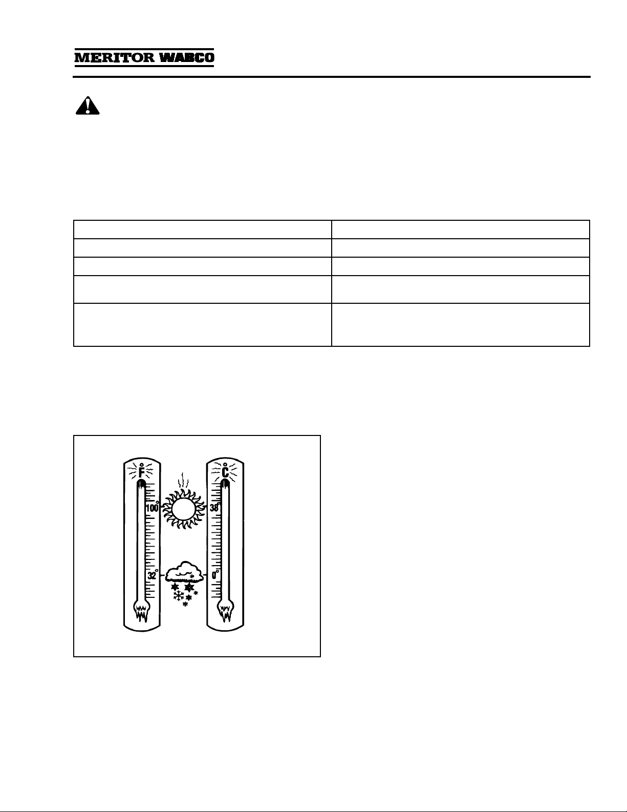
Operating Environment Requirements
System Saver Series Installation Criteria . . . . . . . . . . . . . . . . . . . . . . . . . . . . . . . . . . . . . . . . . . . . . . . . .27
Appendix III: Special Applications
Holset E-Type Compressor Systems . . . . . . . . . . . . . . . . . . . . . . . . . . . . . . . . . . . . . . . . . . . . . . . . . . . . .28
ECON Valve . . . . . . . . . . . . . . . . . . . . . . . . . . . . . . . . . . . . . . . . . . . . . . . . . . . . . . . . . . . . . . . . . . . . . . . . .29
Alcohol Evaporator . . . . . . . . . . . . . . . . . . . . . . . . . . . . . . . . . . . . . . . . . . . . . . . . . . . . . . . . . . . . . . . . . . .31
Combo Tank Installation for Regeneration-Style Air Dryers . . . . . . . . . . . . . . . . . . . . . . . . . . . . . . . . . .32
Combo Tank Installation for Regeneration-Style Air Dryers . . . . . . . . . . . . . . . . . . . . . . . . . . . . . . . . . .33
Meritor WABCO System Saver Series Single Cartridge Air Dryer
Component Replacement Guide — Dedicated Purge . . . . . . . . . . . . . . . . . . . . . . . . . . . . . . . . . . .34
Meritor WABCO System Saver Series Single Cartridge Air Dryer
Component Replacement Guide . . . . . . . . . . . . . . . . . . . . . . . . . . . . . . . . . . . . . . . . . . . . . . . . . . . .35

Section 1
Introduction
MM-34
Revised 11-02 Page 1
Section 1Introduction
System Overview
Maintenance Manual 34 contains troubleshooting
steps and service information for the Meritor
WABCO System Saver Series (1000, 1200 and
1800) single cartridge air dryers.
NOTE:
If you have a System Saver TWIN air dryer,
use Maintenance Manual 35.
Air Dryer Documentation
TP-92116, Installing the Meritor WABCO System
Saver Series Air Dryer, provides complete
installation instructions.
PB-96134 contains a complete listing of air dryer
replacement parts.
TP-97101 is a troubleshooting guide. There is also
a poster-sized troubleshooting guide, TP-9772,
available.
TP-9672, Air Dryer Application Guide, provides
an in-depth look at System Saver Series air
dryer applications.
T-20102V, Air System Troubleshooting video
Stopping With Air and T-97105V, System Saver
1200 videotapes are also available.
To order literature, contact ArvinMeritor’s
Customer Service Center, 800-535-5560.
Air Dryer Identification
Alphabetical designations of the System Saver
Series family of air dryers have specific meanings:
P Indicates an external purge tank is used for
desiccant regeneration
U Indicates discharge line — unloaded
compressor
E Indicates a Holset style compressor function
G Indicates integral governor for air compressor
control
UP Indicates discharge line — unloaded
compressor (with external purge tank)
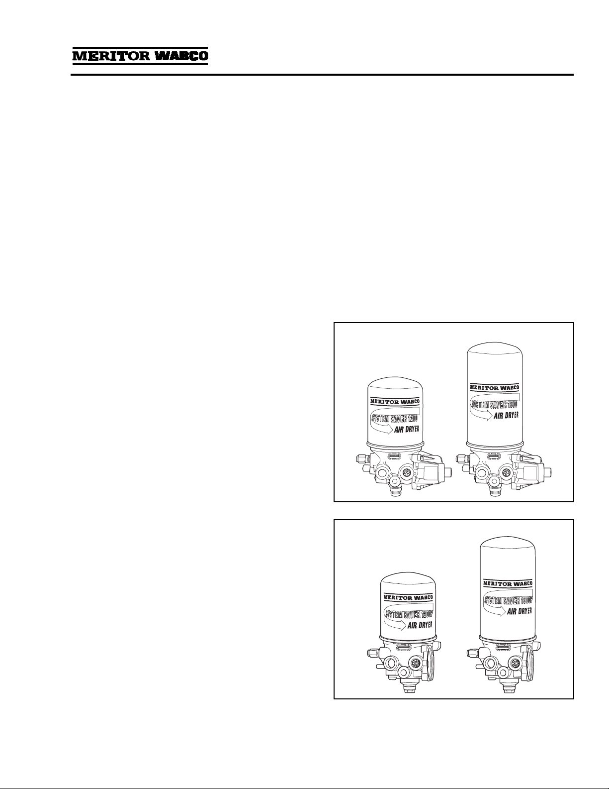
System Saver 1200/1800:
System regeneration
valve assembly on side of dryer
System Saver 1200E:
Tubing and banjo fitting at
front of dryer
System Saver 1200P/1800P:
Uses dedicated purge
tank. Port 22 drilled and tapped
System Saver 1200U/1800U:
Small regeneration
hole visible in back of Port 1 when fitting is
removed. No spring in turbo cut-off valve
assembly.
System Saver 1200UP/1800UP:
Port 22 drilled and
tapped. Small regeneration hole visible at back of
Port 1 when fitting is removed. No spring in turbo
cut-off valve assembly. Dedicated purge tank.
The air dryer base is the same for both the 1200
and 1800 Series air dryers, however the 1800
Series canister is 3.2 inches taller than the 1200.
This larger canister contains 50% more desiccant,
which makes the 1800 ideal for applications calling
for frequent starts, stops and long compressor
cycles. System Saver 1200 and System Saver 1800
Series air dryers are illustrated in
Figure 1.1
.
System Saver 1200P and System Saver 1800P,
which are used with a dedicated purge tank, are
illustrated in
Figure 1.2
.
Figure 1.1
Figure 1.2

Section 1
Introduction
MM-34
Page 2 Revised 11-02
How the Air Dryer Works
During system pressure build-up, compressed air
passes into the air dryer where the filter system
removes contaminants and passes the air into the
drying stage.
Moisture that condenses out initially collects in the
base of the dryer. Moisture-laden air passes
through the desiccant bed in the air dryer
cartridge and is dried. When the compressor
unloads, the water is expelled and dried air flows
back through the dryer, drying the desiccant for
the next cycle.
A typical Meritor WABCO System Saver 1200 or
1800 Series air dryer installation is illustrated in
Figure 1.3
. Illustrations for Combo Tank
installations appear in Appendix III, Special
Applications.
Figure 1.3
1002141c
PURGE
VALVE
(EXHAUST)
COMPRESSOR
DISCHARGE
LINE
COMPRESSOR
CONTROL
(PURGE) PORT
COMPRESSOR
INTAKE LINE
PRESSURE-
CONTROLLED
CHECK VALVE
SUPPLY
TANK
SYSTEM
RESERVOIRS
ONE-WAY
CHECK
VALVE
DRYER
OUTLET
PORT
SYSTEM SAVER SERIES
REGENERATION
STYLE AIR DRYER
DRYER
INLET
PORT
UNLOADER
LINE
RESERVOIR
TO GOVERNOR
LINE
1800
1200
SUPPLY
LINE
PURGE
TANK
PURGE
VALVE
(EXHAUST)
P Series with dedicated
purge tank.
Bottom view
of air dryer.
REGENERATION
VALVE
GOVERNOR
UNLOADER
PORT

Section 1
Introduction
MM-34
Revised 11-02 Page 3
Air Dryer Cycle
A single cartridge air dryer cycle is illustrated below.
The governor turns the compressor on when
supply tank pressure drops below cut-in pressure
(approximately 100 psi).
Compressed air passes into the air dryer at the
inlet port:
O
Moisture-laden air and contaminants pass
through the desiccant.
O
Moisture is retained by desiccant; moisture also
collects in the base of the dryer.
The governor turns the compressor off when
system reaches cut-out pressure (approximately
120 psi).
When the compressor unloads, the purge valve
opens:
O
Dryer purges, expels water collected in dryer
base.
O
Regeneration valve opens:
— Dry system air flows back through the dryer.
10 psi taken from supply and secondary
tanks.
— Back flow dries desiccant, preparing it for
the next cycle.
1002142a
CONTROL
“WET” AIR
“DRY” AIR
CONTROL/DRY
LINES
ENGINE TURBO
BOOST PRESSURE
1002143a
1002145a
CONTROL
“WET” AIR
“DRY” AIR
CONTROL/DRY
LINES
ENGINE TURBO
BOOST PRESSURE
1002144a
Section 1
Introduction
MM-34
Page 4 Revised 11-02
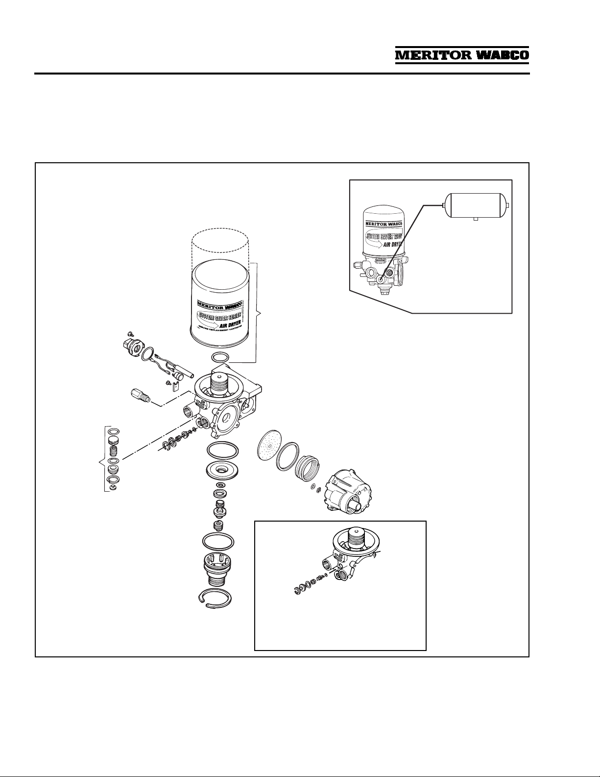
Air Dryer Components
Meritor WABCO single cartridge air dryers contain
replaceable component parts. Air dryer
components are illustrated in
Figure 1.4
. Refer to
Section 3 for instructions.
NOTE:
For information about System Saver E air
dryers and components, refer to Appendix I and
Appendix II. For special applications, refer to
Appendix III.
Figure 1.4
1002146b
SYSTEM SAVER 1200 OR 1800
DESICCANT CARTRIDGE
PRESSURE
RELIEF
VALVE
PURGE
VALVE
ASSEMBLY
REGENERATION VALVE ASSEMBLY
(FOR REGENERATION STYLE AIR
DRYERS)
O-RING
12- OR 24-VOLT
HEATER ASSEMBLY
1200
1800
PURGE
TANK
Port 22 drilled
and tapped for
dedicated purge
style.
BYPASS VALVE
ASSEMBLY
Bypass valve is used on dryers with
date codes earlier than 0894.
1200 Series air dryers do not use
bypass valve.
TURBO
CUT-OFF
VALVE
ASSEMBLY
OUTLET
CHECK
VALVE
ASSEMBLY

Section 1
Introduction
MM-34
Revised 11-02 Page 5
Dryer Identification
The identification tag on the face of the dryer provides important information about the air
dryer — information you will need when servicing or replacing components.
Figure 1.5
.
Description of Components
Replacement components for single canister air dryers are described below.
Figure 1.5
1696
1002147b
SYSTEM
SAVER
1000/1200/1200U
DATE CODE
FIRST 2 DIGITS = BUILD WEEK
LAST 2 DIGITS = BUILD YEAR
MANUFACTURING
LOCATION CODE
SYSTEM
SAVER
1800/1800U
SYSTEM
SAVER
1200E
PART
NUMBER
SYSTEM
SAVER
1200P/1200UP
OR
1800P/1800UP
Figure 1.6
Desiccant Cartridge:
A cylindrical steel housing
containing the filter elements and desiccant
needed to filter and dry system air.
Spin-on/spin-off design allows quick and easy
maintenance. The System Saver 1800 Series
cartridge is 3.2-inches taller than the 1200 Series
cartridge.
Figure 1.6
.
1002148b
1800
1200

Section 1
Introduction
MM-34
Page 6 Revised 11-02
Figure 1.7
Heater:
Located in the air dryer base, the heater
prevents water that collects in the air dryer from
freezing. It consists of a cylindrical resistive-type
heating element and a small circular thermostat.
Heater is available for 12- and 24-volt air dryers.
Figure 1.7
.
1002149a
HEATER MAY BE STAINLESS
STEEL CLAD OR CERAMIC
Figure 1.8
For 1000 Series dryers with date code 0894 or earlier.
Bypass Valve:
A valve located between the inlet
and outlet ports of the dryer. It allows air to flow
into the dryer and go directly to the outlet port,
bypassing the desiccant cartridge. The 1200,
1200E Series and 1000 Series with date codes
later than 0894 do not use a bypass valve.
Figure 1.8
.
1002150a
Figure 1.9
Outlet Check Valve:
A valve located in the outlet
port (port 21) of the air dryer. It prevents air from
flowing back through the air dryer and escaping
out the purge valve during a compressor unload
cycle.
Figure 1.9
.
1002151a
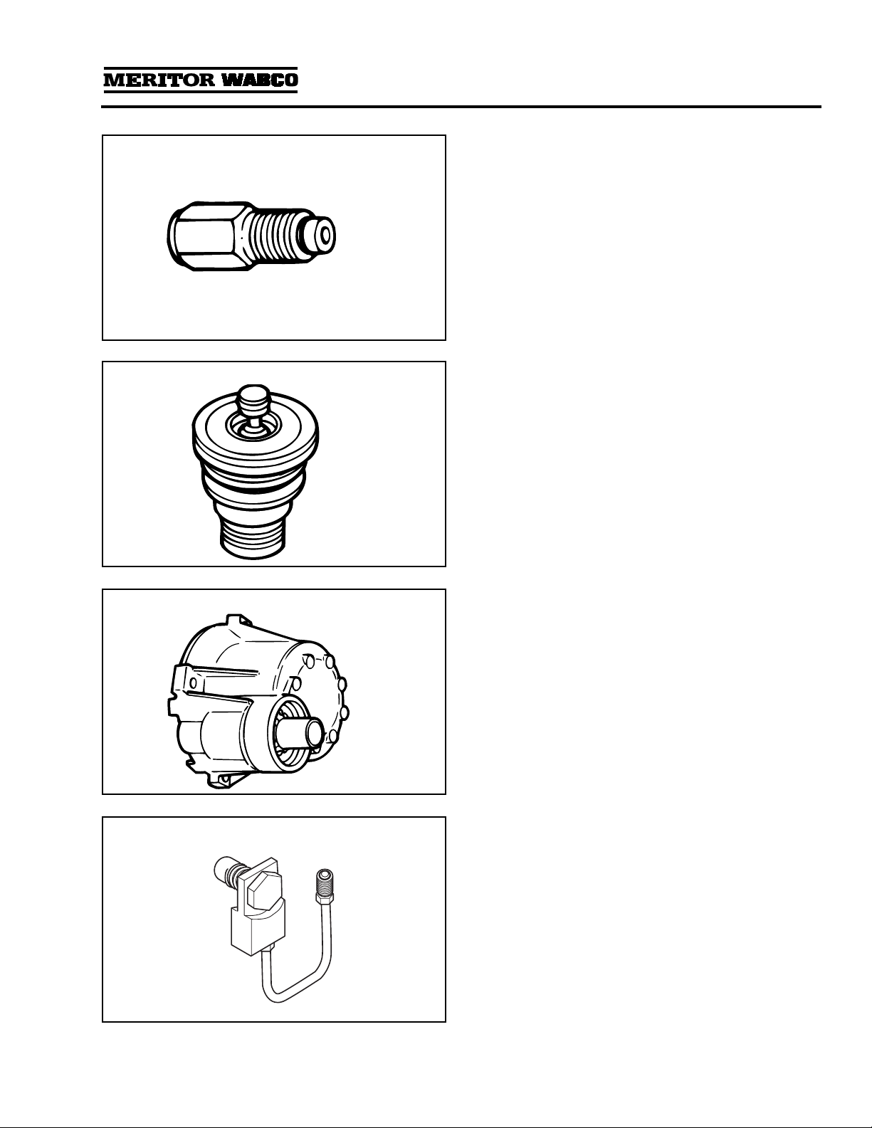
Figure 1.10 Pressure-Controlled Check Valve (PCCV):
Used
with System Saver Series regeneration style air
dryers. The PCCV is usually mounted on the
secondary air tank in place of an inlet check
valve. It lets air backflow from the secondary
tank to the supply tank as long as system
pressure remains between the normal cut-in
and cut-out range of the governor. It allows
additional air volume for generation during the
air dryer purge cycle. Not used with “P” style air
dryers.
Figure 1.10
.
1002152b
AIR FLOW
DIRECTION
Section 1
Introduction
MM-34
Revised 11-02 Page 7
Figure 1.11
Pressure Relief Valve:
A valve that protects the
air dryer from over-pressurization. On dryers
with date codes earlier than 2295, it is installed
in the inlet port of the dryer (port 1) using a
Street-Tee fitting. On dryers with date codes later
than 2295, the pressure relief valve is attached
directly to the air dryer.
Figure 1.11
.
1002153a
Figure 1.12
Purge Valve:
A valve located on the bottom of
the air dryer base that remains open during a
compressor unload cycle. It allows collected
moisture, condensation, and contamination to
be expelled from the air dryer during a purge
cycle.
Figure 1.12
.
1002154a
Figure 1.13
Regeneration Valve:
The valve that controls
regeneration of the desiccant. It allows air from
the supply and secondary tanks to bypass the
outlet check valve. The air expands and
backflushes moisture off of the desiccant, then
out through the dryer’s purge valve.
Figure 1.13
.
Not used with “P” style dryers.
1002155a
Figure 1.14
ECON Valve Replacement Part:
This valve is
used on System Saver Series 1200E single
cartridge air dryers used with Holset E-type
compressors.

Section 1
Introduction
MM-34
Page 8 Revised 11-02
Figure 1.15
ECON Valve:
This valve must be installed if
System Saver 1000 or 1200 Series air dryers
NOT DESIGNATED E are used with Holset E-type
compressors. This valve is not required on
System Saver 1200 E air dryers.
Figure 1.16
Turbo Cut-off Valve:
A valve located in the inlet
port of the air dryer. It closes the path between
the air compressor and the air dryer purge valve
during compressor unload. This prevents a loss
of turbocharger boost pressure during a
compressor unload cycle, thereby maintaining
boost pressure for maximum engine
horsepower.
Figure 1.14
.
There is no spring in the turbo cut-off valve
assemblies used on U Series air dryers.
The System Saver E Series air dryers use a
special turbo cut-off valve. Refer to the air dryer
parts book PB-96134 for part number
information.
1002156a
TOP
SPRING
Figure 1.17
Heater Power Harness:
Twelve-inch cable with
Metri-Pack plug provides electrical connection to
air dryer heating unit.
Figure 1.17
.
1002157a
Figure 1.18
Purge Silencer:
Optional part for all Meritor
WABCO air dryers. It is used to reduce the noise
level of an air dryer purge.
Figure 1.18
.
1002158
Section 2
Troubleshooting & Testing
MM-34
Revised 11-02 Page 9
Section 2Troubleshooting & Testing
WARNING
To prevent serious eye injury, always wear safe
eye protection when you perform vehicle
maintenance or service.
Routine Maintenance
To keep your Meritor WABCO air dryer operating efficiently, the following routine maintenance is
recommended.
Maintenance Tips
The Meritor WABCO air dryer will provide years of reliable service, even under adverse operating
conditions. To provide additional protection against the harmful effects of extreme heat or cold, here are
a few helpful tips.
Meritor WABCO air dryer components are installed in the air dryer at the factory and are designed to last
for the life of the dryer. Under some operating conditions, however, a replacement may be required. Refer
to Section 3 for replacement guide instructions.
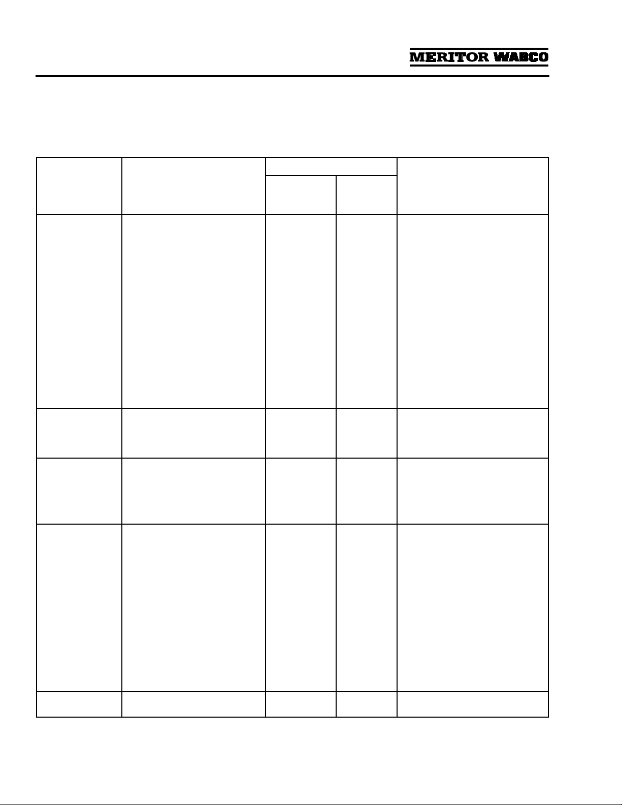
Interval Required Action
Weekly. Ensure dryer purges when compressor unloads.
Weekly, or as recommended by the manufacturer. Drain purge tank (dedicated purge tank dryers).
Weekly, or as recommended by the manufacturer,
whichever is most frequent. Check for moisture in the system by opening the
drain cock slowly.
O
Every 2-3 years, or more often depending on usage,
vocation, and condition of compressor.
O
Whenever compressor is rebuilt.
Replace the desiccant cartridge.
Figure 2.1
Dedicated Purge Tank
Optimum mounting location for the dedicated
purge tank is
ABOVE
the air dryer.
Extreme Heat
Make sure the compressor discharge line is
long enough to keep inlet air below 175°F
(80°C). (Refer to Operating Environment
Requirements in Appendix II.)
Extreme Cold
Make sure the air dryer heater is in good
working order by running a heater resistance
test. Refer to Heater Resistance in this section.
Check the line from the governor to port 4 of the
dryer for oil and/or water. Keep this line clean to
help prevent freezing.
1002159a
Section 2
Troubleshooting & Testing
MM-34
Page 10 Revised 11-02
Troubleshooting
Conditions you may experience, and suggested
solutions, appear in the following System Saver
Series Air Dryer Troubleshooting table.
NOTE:
The exploded view of the System Saver
single canister air dryer in Section 1 illustrates the
location of components in the dryer.
Condition Possible Cause
Conditions May Occur In:
Solution
Regeneration
Style Air
Dryers
Dedicated
Purge Tank
Air Dryers
Dryer leaks from
purge valve during
compressor
loaded cycle. The
leak may cause
excessive
compressor
cycling or prevent
the system from
building air
pressure.
Purge valve frozen open (cold
weather operation).
Debris under purge valve seat,
such as particles from fittings or
air inlet line.
Purge valve washer installed
upside-down.
Wrong air line connected to dryer
port 4 (unloader port).
Purge valve snap ring not fully
seated in groove.
Yes Yes Check heater. Repair/replace if
necessary. Make sure governor to
dryer port 4 line is free of water/oil.
Remove and inspect purge valve
and clean water/oil from top of
piston.
Disassemble and clean purge valve.
Remove cartridge and clean dryer
sump area.
Ensure lip on aluminum washer
faces
DOWN
, away from dryer.
Verify correct air line installation
and correct as needed.
Seat snap ring fully into groove.
Slight leak from
purge valve. After
several hours, the
supply tank may
be empty.
Outlet check valve not seating or
regeneration valve not shutting
off regeneration airflow.
Yes No Remove, inspect, and clean outlet
check valve and regeneration valve
diaphragm. Replace if worn or
damaged.
Regeneration
cycle too long
(more than
30 seconds),
accompanied by
loss of pressure in
the supply tank.
Outlet check valve not seating.
Regeneration valve not shutting
off regeneration airflow.
Yes
Yes
Yes
No
Inspect and replace outlet check
valve as needed.
Replace regeneration valve.
Regeneration
cycle too short
(less than
10 seconds).
High air system demands during
compressor unloaded cycle.
Pressure-controlled check valve
not installed in system or not
working properly.
One-way check valve installed in
system reservoir instead of, or
with, pressure-controlled check
valve.
Regeneration valve not working.
Air governor not working
properly.
Yes
Yes
Yes
Yes
Yes
Yes
No
No
No
Yes
Increase air system capacity or
reduce air demands.
Check and replace pressure-
controlled check valve as needed.
Remove one-way check valve. Make
sure pressure-controlled check
valve is installed correctly.
Remove regeneration valve and
clean oil from diaphragm. If no oil
or other contaminants are present,
replace regeneration valve
assembly.
Inspect per manufacturer’s
instructions and repair/replace as
needed.
Water in purge
tank Block in purge tank line. N/A Yes Clear blockage. Replace desiccant
cartridge.
Section 2
Troubleshooting & Testing
MM-34
Revised 11-02 Page 11
No regeneration
cycle. No airflow
from purge valve
after initial purge
blast (dryer
decompression).
Air dryer not connected to supply
tank or connections reversed at
dryer.
Regeneration valve not working.
One-way check valve installed in
supply tank.
Alcohol evaporator installed
between dryer and supply tank.
Blocked line/pinched line from
purge tank.
Yes
Yes
Yes
Yes
No
No
No
No
No
Yes
Verify proper dryer installation per
system diagram.
Replace regeneration valve.
Remove one-way check valve.
Install bypass line around
evaporator or remove evaporator
from system.
Clear/repair line.
Air dryer does not
purge when
compressor
unloads (no blast
of air from purge
valve).
Air line between governor and air
dryer port 4 kinked or plugged.
Purge valve stuck closed.
Air governor not working
properly.
Cut-out pressure never achieved
by air compressor.
Yes
Yes
Yes
Yes
Yes
Yes
Yes
Yes
Repair air line.
Replace purge valve.
Inspect air governor. Repair/replace
per manufacturer’s instructions.
Check for air leaks in system and
repair as needed. If no leaks in
system, check compressor output.
Repair/replace per manufacturer’s
instructions.
Air dryer purges
too often, perhaps
as frequently as
every 15 seconds,
accompanied by
excessive cycling
of the compressor.
Leak in line between governor
and dryer port 4.
Leak in line between supply tank
and governor.
Excessive air system leaks.
Excessive air system demands.
Outlet check valve not seating.
Regeneration valve not shutting
off properly.
Air governor has less than 16 psi
range.
Leaking air compressor
unloader(s).
Yes
Yes
Yes
Yes
Yes
Yes
Yes
Yes
No
Yes
Yes
Yes
Yes
No
Yes
Yes
Repair air line.
Repair air line.
Repair leaks.
Increase air system capacity or
reduce air demand.
Inspect and replace outlet check
valve as needed.
Replace regeneration valve.
Replace air governor.
Inspect compressor. Repair/replace
per manufacturer’s instructions.
Air flows out of
purge valve entire
time compressor
is unloaded.
Turbo cut-off valve not sealing.
NOTE:
With U Series air dryers
the compressor unloads through
the dryer, so a steady flow of air
is normal.
Yes No Replace turbo cut-off valve.
Rapid “spitting” of
air from purge
valve in small
amounts.
Frequency varies
with engine speed.
Holset E-type compressor used,
but no Econ valve installed.
Compressor not completely
unloading when cut-out pressure
is reached.
Yes
Yes
Yes
Yes
Install Econ valve to provide
make-up air to compressor.
Inspect compressor. Repair/replace
per manufacturer’s instructions.
Air leak at turbo
cut-off valve vent.
Hole burned in
piston.
Temperature of air coming into
dryer is too high — not enough
cooling takes place before dryer
inlet.
Yes Yes Move dryer farther from
compressor. Add additional
compressor discharge line before
air dryer. Add cooling coil or heat
exchanger before air dryer.
NOTE:
Inlet air temperature must
not exceed 175°F (80°C).
Condition Possible Cause
Conditions May Occur In:
Solution
Regeneration
Style Air
Dryers
Dedicated
Purge Tank
Air Dryers

Section 2
Troubleshooting & Testing
MM-34
Page 12 Revised 11-02
Air leak at turbo
cut-off valve vent. Lip seal installed upside-down on
piston. Lip must face UP (towards
dryer).
Valve bore worn excessively.
Yes
Yes
Yes
Yes
Install lip seal correctly.
Inspect valve bore for wear. If a new
turbo cut-off valve does not seal in
a clean, lubricated bore, replace the
air dryer.
Air dryer frozen
(water collecting
in base of dryer is
freezing).
No electrical power to heater
connector.
Low voltage to heater connector.
Heater assembly not working.
Wrong voltage air dryer used; i.e.,
12-volt air dryer used in a 24-volt
system.
Yes
Yes
Yes
Yes
Yes
Yes
Yes
Yes
Yes
Yes
Check for a blown fuse. Repair
heater circuit.
NOTE:
There must be power to the
heater connector the entire time the
vehicle’s ignition is
ON
.
Repair cause of low voltage, such
as poor electrical ground, bad
connections, corroded wire splices,
etc.
Replace heater assembly.
Replace with correct voltage air
dryer.
No air pressure
build-up in
system.
Air dryer not plumbed correctly
(connections reversed).
Wrong air line connected to dryer
port 4.
Air governor not working
properly.
Air system leaks, such as
compressor discharge line, air
dryer, reservoirs, brake or
suspension valves, etc.
Air dryer leaks from purge valve.
Yes
Yes
Yes
Yes
Yes
Yes
Yes
Yes
Yes
Yes
Ensure compressor discharge line
is plumbed to air dryer port 1, and
air dryer port 21 is connected to
vehicle’s supply tank.
Ensure dryer port 4 line is
connected to the “UNL” port of the
air governor.
Inspect governor per
manufacturer’s instructions. Repair
or replace as needed.
Locate leak(s) and repair.
Refer to purge valve conditions
listed in this chart.
Water in tanks;
often following
aftermarket
installation or
when dryer is a
replacement for a
competitive brand.
Pressure-controlled check valve
not installed in correct tank or not
installed at all.
Pressure-controlled check valve
properly installed, but one-way
check valve not removed.
Yes
Yes
No
No
Install pressure-controlled check
valve in secondary tank.
Remove one-way check valve so
that only the pressure-controlled
check valve is installed between the
secondary tank and supply tank.
Water, oil, or
sludge in air
system tanks.
Desiccant contaminated with oil. Yes Yes Replace desiccant. Inspect
compressor per manufacturer’s
instructions.
Water in system
tanks, everything
else checks out
okay.
Dryer not suitable for application. Yes Yes Review application guidelines. For
assistance, call ArvinMeritor’s
Customer Service Center at
800-535-5560.
Condition Possible Cause
Conditions May Occur In:
Solution
Regeneration
Style Air
Dryers
Dedicated
Purge Tank
Air Dryers
Section 2
Troubleshooting & Testing
MM-34
Revised 11-02 Page 13
System Tests
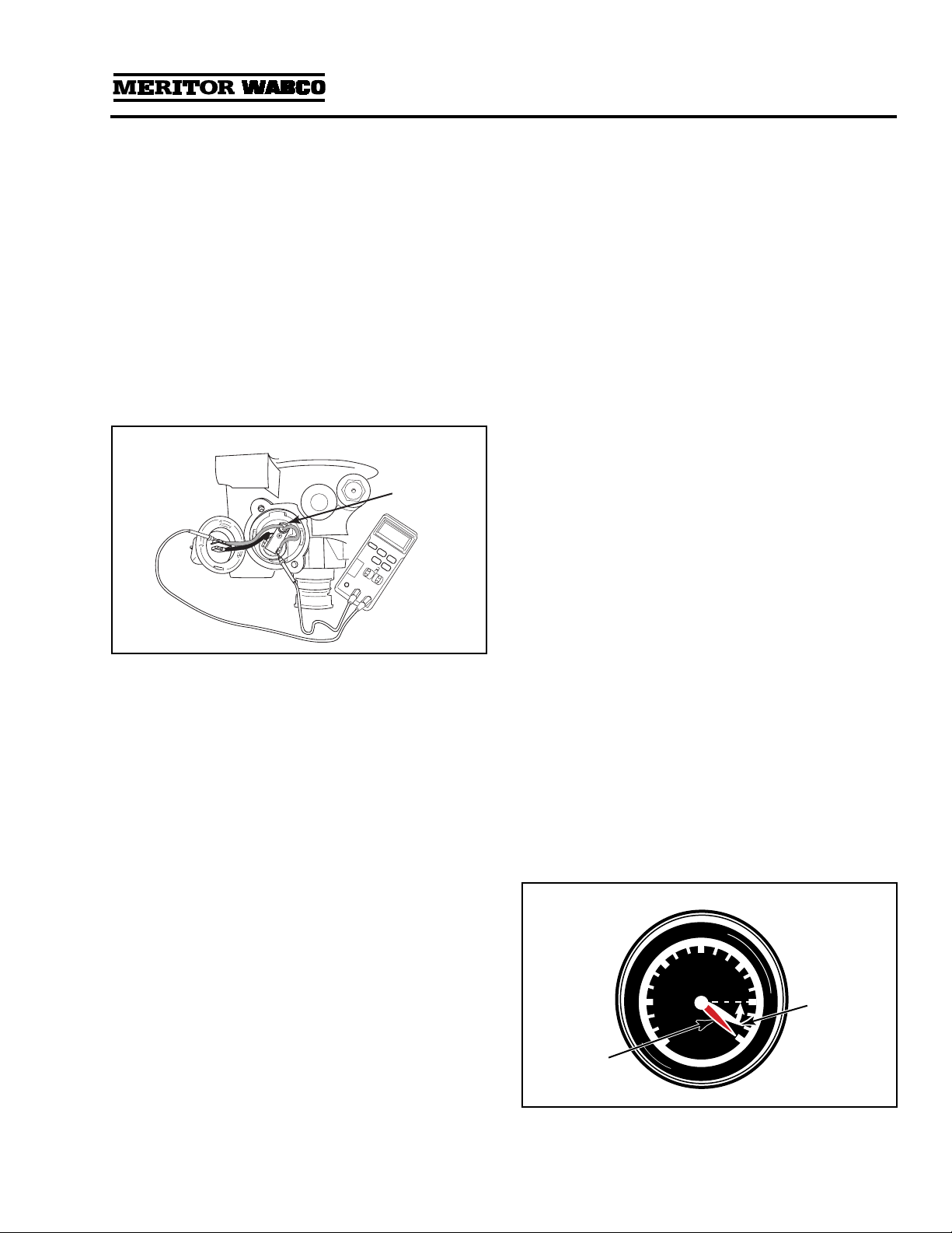
Heater Resistance
To avoid damaging components, Meritor WABCO
recommends performing this resistance check
with the heater in place.
1. Set volt-ohmmeter to ohms.
2. Disconnect vehicle harness at the heater.
3. Remove the two screws holding the external
components in place.
4. With wires connected and properly secured,
touch one probe to each heater element lead.
5. Measure the resistance. Acceptable resistance
is:
O12 Volt: 1.0-2.0 ohms
O24 Volt: 5.0-7.0 ohms
If resistance is less than 1.0 ohm for a 12-volt
or 5.0 ohms for a 24-volt system, replace the
heater.
6. Reinstall components and vehicle harness.
Leak Test
1. Drain air from all system tanks.
2. Close reservoir draincocks.
3. Start the vehicle. Allow air system pressure to
build while engine idles.
4. When the system reaches cut-out pressure
there will be a purge, or strong blast of air,
followed by a mild flow which will last
10-25 seconds.
5. Shut off the engine.
6. Apply a soap solution to each connection that
contains pressurized air. Check the
connections to see if soap solution bubbles.
No Soap Bubbles: Connections are sealed
properly.
Soap Bubbles Appear: Connections are NOT
sealed properly.
To repair improperly sealed connections:
1. Drain all reservoirs.
2. Remove leaking connection.
3. Inspect the connectors and ports for damaged
threads or cracks. Replace if necessary.
4. Apply pipe sealant to the connection.
NOTE: Repeat leak test until all connections are
sealed.
Air Pressure Checks
NOTE: When checking air pressure during these
tests, do not rely on cab air gauges for accurate
readings. Install a calibrated air gauge (accurate to
within 1 psi) in the secondary air tank for making
determinations about the continued use or
replacement of equipment.
Operational Test for System Saver
Series Air Dryers — Regeneration
and Purge Style
1. Check compressor loaded and unloaded cycle.
When the compressor is in the loaded cycle,
air pressure will build to approximately 120 psi
(cut-out pressure). When the compressor
reaches the unloaded cycle, the air dryer will
purge, initiating regeneration of the air dryer.
Figure 2.2
HEATER
Figure 2.3
PSI
20
40
60 80 100
110
120
1002161a
Primary
Air Supply
(Red)
Secondary
Air Supply
(White)
Section 2
Troubleshooting & Testing
MM-34
Page 14 Revised 11-02
2. During the regeneration cycle, which lasts
from 10-25 seconds, supply and secondary
tanks will drop approximately 10 psi in
pressure. Check the secondary air gauge on
the vehicle dash panel to verify this drop.
NOTE: A 10 psi drop in pressure in the
secondary air system is normal for Meritor
WABCO System Saver Series regeneration
style air dryers. There should be no visible
pressure drop for P Series dryers. If there is a
visible pressure drop (P Series dryer), perform
a check valve leak test on the system check
valves.
Step 3 applies to regeneration style air dryers only.
3. If there is no drop in pressure, one of the
following conditions may apply:
OPressure-controlled check valve not
installed, or installed on wrong air tank.
OPressure-controlled check valve installed to
a one-way check valve, instead of in place of
a one-way check valve.
OThere is another check valve located
between the air dryer and the secondary air
tank, usually at the supply tank.
OSecondary air gauge not plumbed to the
secondary air system. Use a calibrated air
gauge in the secondary tank to check air
pressure.
— Make the necessary installation changes
or repairs and repeat the operational test.
OIf the secondary pressure drops 25 psi or
more during the regeneration cycle — and
there are no other air-operated components
using air during this cycle — there are air
leaks or other air system problems.
— Identify and repair all air leaks and air
system problems.
— Clean the Regeneration and Outlet Check
valves.
— Disconnect the compressor line from the
air dryer (Dryer Port 4). Check the
compressor and governor per the
manufacturer’s recommendation.
Pressure-Controlled Check Valve
Test — Regeneration Style Only
1. Turn off the engine after the air system reaches
cut-out pressure (approximately
120 psi) and the air compressor has unloaded.
2. Drain the supply tank down to 80 psi or lower.
3. Check the secondary tank air gauge. It should
read 95 ± 5 psi.
NOTE: A drop from 120 to 95 ± 5 psi during
this test is normal for vehicles equipped with
the System Saver Series air dryer and a
pressure-controlled check valve.
4. If the secondary tank air gauge reading is less
than 90 psi:
OPressure-controlled check valve may be
installed backwards (arrow on valve must
point toward host reservoir). Make
necessary corrections and retest.
OCheck for leaks in the secondary air system.
Identify and repair any leaks.
5. If the secondary tank air gauge reading does
not change — or the reading does not drop
below 100 psi:
OPressure-controlled check valve not
installed, or installed on wrong air tank.
OPressure-controlled check valve installed TO
a one-way check valve, rather than IN PLACE
OF a one-way check valve.
OThere is another check valve located
between the air dryer and the secondary air
tank, usually at the supply tank.
OSecondary air gauge not plumbed to the
secondary air system. Use a calibrated air
gauge in the secondary tank to check air
pressure.
— Make the necessary installation changes
or repairs and repeat the operational
test.
Figure 2.4
PSI
20
40
60 80 95
110
120
1002162a
Primary
Air Supply
(Red)
Secondary
Air Supply
(White)

Section 3
Installing Replacement Parts
MM-34
Revised 11-02 Page 15
Section 3Installing Replacement Parts
WARNING
To prevent serious eye injury, always wear safe
eye protection when you perform vehicle
maintenance or service.
Remove all pressure from the air system before
you disconnect any component, including the
desiccant cartridge. Pressurized air can cause
serious personal injury.
Park the vehicle on a level surface. Block the
wheels to prevent the vehicle from moving.
Serious personal injury can result.
Replacement Requirements
Before replacing any air dryer component, make
sure the air compressor and air governor are
working properly. Repair or replace these parts, if
necessary. Check the entire air system for leaks,
and repair as necessary. When draining air tanks
before servicing the air dryer, check for water
and/or oil that may have accumulated in the tanks.
Water and/or oil in the air tanks could indicate a
problem with the dryer or compressor.
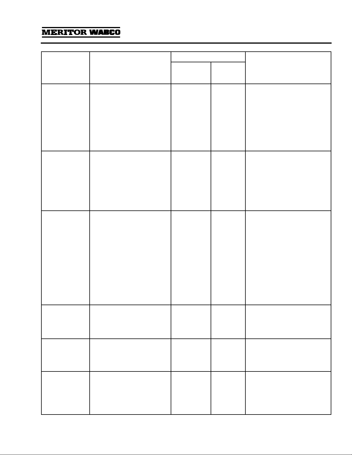
Replacement Requirements
Component When to Replace Why
Desiccant Cartridge Every two to three years. Preventative maintenance.
When compressor is replaced. Contaminated cartridge.
Water in supply tank. Saturated or contaminated cartridge, high duty
cycle (wrong application of air dryer).
Bypass Valve (dryers with
date codes earlier than
0894)
Valve leaking, inlet to outlet. Cut O-ring, bad seat.
Heater Assembly Water collecting in air dryer is freezing —
electrical power to dryer is O.K. Heater assembly not working (internal short or
open circuit).
Outlet Check Valve Air continues to flow from purge valve after
purge cycle, but stops flowing when the
compressor load cycle begins.
Valve is stuck in the open position, or not
functioning properly.
No pressure build-up in system, everything
else is O.K. Valve is stuck in closed position.
Purge Valve No purge cycle when compressor unloads —
normal pressure at dryer control port 4
(governor port).
Valve is stuck in the closed position, or not
functioning properly.
Air flows from purge valve during
compressor’s load cycle — no pressure at dryer
control port.
Valve is stuck in the open position, or not
functioning properly.
Turbo Cut-Off Valve Air flows from purge valve during compressor
unload cycle after purge cycle, and flow is
noticeably stronger at high engine RPM,
especially under load.
Turbo cut-off valve leaking.
No pressure build-up in system — high
compressor discharge line pressure. Valve stuck in closed position.
Regeneration Valve Regeneration cycle continues after compressor
begins, and secondary tank pressure drops
15 psi or more.
Regeneration valve allowing too much air to
come back into cartridge.
Purge cycle is too short (5 seconds or less) —
pressure-controlled check valve is O.K., no leak
in governor control line.
Regeneration valve not allowing enough air to
come back into cartridge.
Air dryer purges — but no regeneration, no
check valve between air dryer and supply tank,
and purge valve has not closed.
Regeneration valve not allowing any air to
come back into cartridge.
Pressure-Controlled
Check Valve Regeneration cycle too short; may result in
water in tank. Valve checks (stops airflow) too high.
Section 3
Installing Replacement Parts
MM-34
Page 16 Revised 11-02
NOTE: When replacing air dryer components, use
only Meritor WABCO replacement parts.
The exploded view of the air dryer in Section 1
shows the location of the various air dryer
components.
Component Replacement
WARNING
To prevent serious eye injury, always wear safe
eye protection when you perform vehicle
maintenance or service.
Remove all pressure from the air system before
you disconnect any component, including the
desiccant cartridge. Pressurized air can cause
serious personal injury.
Park the vehicle on a level surface. Block the
wheels to prevent the vehicle from moving.
Support the vehicle with safety stands. Do not
work under a vehicle supported only by jacks.
Jacks can slip and fall over. Serious personal injury
can result.
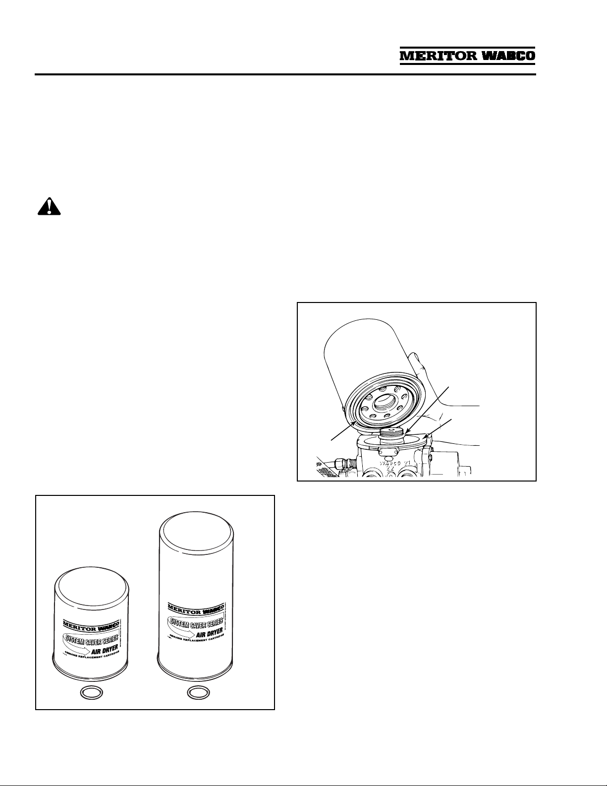
Desiccant Cartridge
1. Replacement kit contains one cartridge and
one O-ring. Figure 3.1.
NOTE: Replacement cartridges are marked
“System Saver Series.”
2. Loosen and remove the old cartridge. Use
strap wrench if necessary.
3. Remove and discard O-ring from dryer base.
4. Inspect and clean seal seat. Repair any minor
damage.
NOTE: If seats are damaged so badly that a
tight seal cannot be maintained, replace the air
dryer.
5. Lubricate and install new O-ring on stem.
6. Lubricate cartridge seal.
7. Thread replacement cartridge onto the base
until the seal touches the base. Then, tighten
the cartridge ONE addition turn. DO NOT
OVERTIGHTEN. Figure 3.2.
Figure 3.1
1002163b
1800
1200
Figure 3.2
1002164a
SEAL
SEAL SEAT
O-RING
This manual suits for next models
7
Table of contents


