DEI PVX-4000-2kV-EX User manual

PVX-4000-2kV-EX
Pulsed Voltage Source
Operation Manual
Directed Energy, Inc.
1609 Oakridge Dr., Suite 100, Fort Collins, CO 80525
(970) 493-1901
www.ixyscolorado.com
Manual Document 7650-0024 Rev. A02
© Copyright 2017 IXYS Colorado. All rights reserved.


Contents
Contents....................................................................................................................................................................3
Safety.........................................................................................................................................................................5
Introduction...............................................................................................................................................................6
Description....................................................................................................................................................6
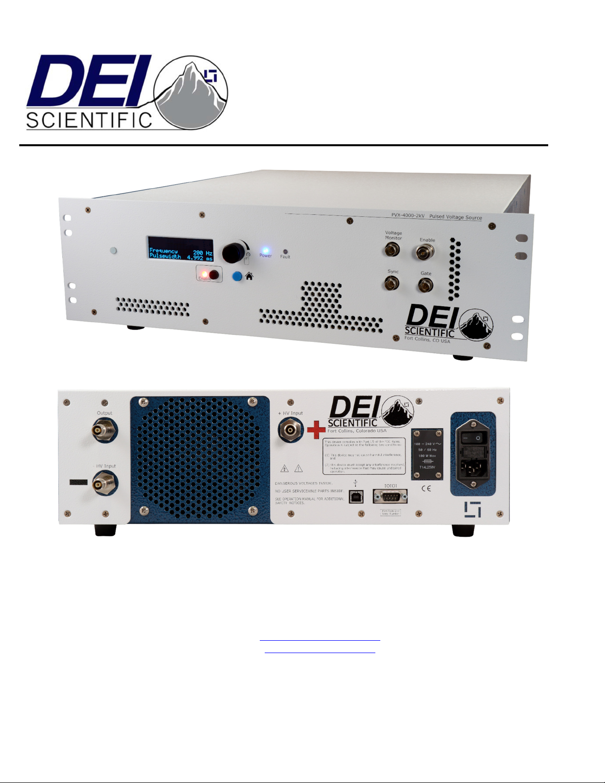
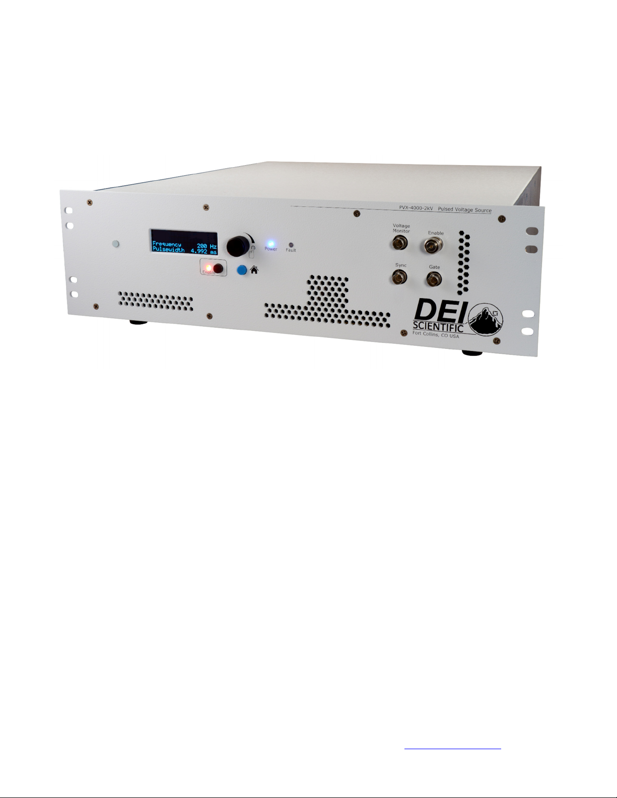
FrontPanelFeatures.....................................................................................................................................7
RearPanelFeatures.......................................................................................................................................9
AccessoriesIncluded...................................................................................................................................10
OperatingConsiderations........................................................................................................................................11
OutputCabling.............................................................................................................................................11
PulseVoltages..............................................................................................................................................11
TriggerMethod............................................................................................................................................11
LocalOperation.......................................................................................................................................................12
LocalMode..................................................................................................................................................12
Setup............................................................................................................................................................12
PowerUp.....................................................................................................................................................13
SettheOutputVoltage................................................................................................................................13
SettheTriggerType.....................................................................................................................................13
SettheFrequency........................................................................................................................................13
SetthePulseWidth.....................................................................................................................................14
EnableSystemOutput.................................................................................................................................14
PowerDown................................................................................................................................................15
SaveSystemSetup.......................................................................................................................................15
RestoreSystemSetup..................................................................................................................................15
RemoteOperation...................................................................................................................................................16
RemoteMode..............................................................................................................................................16
CommandList..............................................................................................................................................17

FaultCodes..................................................................................................................................................19
WarrantyandService..............................................................................................................................................20
Warranty......................................................................................................................................................20
FactoryServiceandSupport........................................................................................................................21
DeclarationofConformity.......................................................................................................................................22

Page5of24
Document#7650‐0024RevA02.©Copyright2017IXYSColorado.Allrightsreserved.
Safety
Always refer to the Safe Operating Area (SOA) of the PVX-4000-2kV-EX system, located
in the datasheet.
Do not open the cover of the PVX-4000-2kV-EX. There are no user-serviceable parts
inside. Opening the cover exposes you to shock and voids the factory warranty.
Do not install, handle, or remove the output cables or load while the PVX-4000-2kV-EX
is operating. Allow at least 10 minutes after powering down before handling the output
cable or load.
Do not use this device in a manner not specified by the manufacturer.
Allow sufficient space around this device for air circulation.
Do not use where liquids are present or in corrosive environments. Clean this instrument
by wiping with a dry or damp cloth.
WARNING
Risk of lethal electric shock. Do not open the cabinet of this device. Do not touch the
output or load while it is operating. This device produces LETHAL levels of electric
current, both inside its cabinet and at its output.
DO NOT OPERATE THIS DEVICE UNLESS ANOTHER PERSON, CAPABLE OF RENDERING
FIRST AID OR RESUSCITATION, IS PRESENT.
SAFE AND PROPER OPERATION OF THIS DEVICE IS THE RESPONSIBILITY OF THE
USER.
Directed Energy, Inc. (DEI) provides information on its products and associated hazards, but it
assumes no responsibility for the after-sale operation and safety practices.

Page6of24
Document#7650‐0024RevA02.©Copyright2017IXYSColorado.Allrightsreserved.
Introduction
Description
The PVX-4000-2kV-EX is an air-cooled pulse generator that produces high voltage
waveforms. Optimized for high-impedance capacitive loads, the PVX-4000-2kV-EX is well
suited for driving extraction grids and deflection plates for electrostatic modulation of particle
beams in time-of-flight mass spectrometers and accelerators. The system is capable of duty
cycles from 2% to 98% and repetition rates from 40 Hz to 30,000 Hz using the internal trigger.
With the external trigger the system is capable of single shot to 600 kHz with a pulse width
of 500 ns to 100% duty cycle.
The PVX-4000-2kV-EX requires external high-voltage power supply sources from 0 V to
±2000 V. For example, a +1000 V supply can be connected to the positive voltage input, and
a -1000 V supply can be connected to the negative voltage input, for a total of 2000 V. It is
the customer responsibility to verify the high-voltage power supplies do not exceed the total
of 2000 V.
ThepositiveandnegativehighvoltageinputlevelsmustNOTexceed2000Vtotal.Reducethe
highvoltageinputoneitherchanneltoachieve≤2000V.Usethebelowformula:
Vpositive+|Vnegative|≤2000V
Conveniently-located front panel BNC connectors allow the PVX-4000-2kV-EX to be
externally gated and synchronized for specialized interconnected equipment applications.
The external gate input impedance and the sync output impedance are both 50 . The sync
output pulse is synchronized to the leading edge of the output voltage pulse and is active
with the either internal or external trigger.
The PVX-4000-2kV-EX has a pulse generator incorporated into the system. This provides a
test system that can be programmed to perform device testing using the front panel LCD
controls or a computer interface (RS-232 and USB).
When changing the frequency, the duty cycle will be maintained. The system will display the
new pulse width that changes to maintain the duty cycle. It is recommended to change the
frequency before changing the pulse width.
Up to five user configurations may be stored in internal nonvolatile memory and recalled
through the front panel or communications interface. The first memory location stores the
power-up default parameters.

Page7of24
Document#7650‐0024RevA02.©Copyright2017IXYSColorado.Allrightsreserved.
All error and fault messages are reported on the front panel display and are also available
via the computer communications interface. Analog voltage monitors are also provided for
monitoring the voltage to the load using an external oscilloscope.
Front Panel Features
Power LED
The Power LED is lit when there is support power applied to the PVX-4000-2kV-EX.
Fault LED
The Fault LED is lit when there is a fault/error sensed within the system.
Enable LED
The Enable LED is lit, and the system output is enabled, when all the following conditions
are met:
There are no faults
The enable BNC connection is made
The enable button has been pressed
Enable Button
The Enable button, press this button to enable and disable the system output.
Home Button
The Home button, press this button to return to the main menu, once all parameters have
been set to the user values.

Page8of24
Document#7650‐0024RevA02.©Copyright2017IXYSColorado.Allrightsreserved.
Encoder Knob
The encoder changes the values of the displayed parameters.
LED Display
The display shows system information on the home screen. It is used in conjunction with the
encoder.
Enable Input
The Enable BNC input accepts either an external dry-contact closure or the factory-supplied
shorting BNC plug (PCA-9410).
Closed contacts or use of the shorting plug allows the output to be enabled. Less than
1000 will allow the system to be enabled.
Open contacts or removal of the shorting plug disables the output and creates a fault.
Greater than 1 Mwill disable the system.
Voltage Monitor Output
The Voltage Monitor (VMON) BNC output allows the user to monitor the voltage and signal of
the output cable. The VMON voltage is linearly scaled with a ratio of 10:1000. For example,
1000 V at the output corresponds to 10 V on VMON.The oscilloscope termination should be
set to 1 M.
Gate Input
The Gate (external gate) BNC input accepts trigger pulses from an external source. Its input
impedance is 50 and it should be driven with a 5 V logic level source. The frequency range
is single shot to 600 kHz and the pulse width is 500 ns to DC.
Sync Output
The Sync BNC output provides synchronization pulses for external devices. The sync pulse
corresponds to the leading edge of the output pulse. Its impedance is 50 with voltage levels
of 0 V to > +3.3 V.

Page9of24
Document#7650‐0024RevA02.©Copyright2017IXYSColorado.Allrightsreserved.
Rear Panel Features
Pulsed Output
A Winchester Kings 10 kV, 1065-2 plug is the output connection for system-generated
voltage pulses. DO NOT TOUCH any part of this output or cable while the PVX-4000-2kV-
EX is powered up and enabled. Please review the Safety section.
Positive High Voltage Input
A Winchester Kings 10 kV, 1065-2 plug is the input connection for the customer-provided
positive high voltage power supply. DO NOT TOUCH any part of this input or cable while the
PVX-4000-2kV-EX is powered up and enabled. Please review the Safety section.
Negative High Voltage Input
A Winchester Kings 10 kV, 1065-2 plug is the input connection for the customer-provided
negative high voltage power supply. DO NOT TOUCH any part of this input or cable while
the PVX-4000-2kV-EX is powered up and enabled. Please review the Safety section.
Power Cord Connector
The power cord connector accepts a type NEMA C14 grounding equipment power cord.
On/Off Power Switch
The On/Off switch turns the PVX-4000-2kV-EX support power on and off.
Communication
The system can communicate with a computer using USB or RS-232 for automated program
operation.
The RS-232 Interface operates with settings of 115,200 baud, 8 data bits, 1 stop bit,
no parity, and no flow control.
The USB Interface operates as a COM port with settings of 115,200 baud, 8 data
bits, 1 stop bit, no parity, and no flow control. The driver can be found on our website.
When switching communication from RS-232 to USB, no power cycle is needed.

Page10of24
Document#7650‐0024RevA02.©Copyright2017IXYSColorado.Allrightsreserved.
When switching communication from USB to RS-232, the PVX-4000-2kV-EX must be
power cycled.
Accessories Included
AC Power Cord
The factory-supplied power cord is a type NEMA C14 grounding equipment power cord.
Pulsed Output Cable
The output cable (PCA-9400) is used to connect the PVX-4000-2kV-EX to the load and is
two meters in length. The factory supplied output cable has 1.57 pF / 1.0 cm of cable. This
needs to be calculated into the total load value.
DC Voltage Input Cables
The input cables (PCA-9400) are used to connect the PVX-4000-2kV-EX to the customer
provided high voltage power supplies and are two meters in length. If the customer is only
using one polarity of high voltage power supply, then the customer should short the other
polarity to the chassis, this is to ensure the other polarity is not floating above or below
ground.

Page11of24
Document#7650‐0024RevA02.©Copyright2017IXYSColorado.Allrightsreserved.
Operating Considerations
Output Cabling
The PVX-4000-2kV-EX is designed to drive capacitive loads. Since its output current is
limited, a smaller load capacitance results in a faster rise time. If the load characteristics are
fixed, only the length and type of interconnecting cable will change the output capacitance.
The unit is supplied with a two-meter length of insulated coaxial cable. DEI recommends that
the shortest length of cable possible be used to ensure the fastest possible rise times and
best pulse fidelity.
This unit was tested driving a 344 pF load at 2000 V output. The load consisted of a 56 pF
capacitor at the end of a two meters of coaxial cable with a characteristic capacitance of 1.57
pF / 1.0 cm of cable. This needs to be calculated into the total load value.
Pulse Voltages
The PVX-4000-2kV-EX pulser is rated at a maximum pulse output voltage of ±2000 V DC.
Proper precautions should be taken by the user to ensure that the maximum voltage is not
exceeded. Never exceed the ±2000 V DC maximum input voltage from the customer
supplied high voltage power supplies.
Trigger Method
Use either the internal trigger source or an external gate to trigger the output pulse.

Page12of24
Document#7650‐0024RevA02.©Copyright2017IXYSColorado.Allrightsreserved.
Local Operation
Local Mode
Two modes of operation are possible, Local and Remote. Local Mode is automatically
selected on power up, allowing the user to change the system configuration through the front
panel display and the encoder knob/button. The user can:
Set the trigger mode (internal or external)
Set the frequency
Set the pulse width
Save a configuration to memory
Load a configuration from memory
Enable and disable the output
Reset a fault
View the RS-232/USB port settings
View the system status (temperature)
Press the encoder to change and update the values of the various parameters. On some
menus, pressing the encoder allows the user to change the multiplier.
Setup
1. Press the Enable button to disable the voltage output of the system.
2. The PVX-4000-2kV-EX should be OFF for at least ten minutes when connecting or
disconnecting the voltage output connector.
3. Connect the customer supplied high voltage power supplies to the positive input and
negative input connectors. Verify the polarity is correct on the input cables. The center
pin is the high voltage and the housing is the return.
Connect both power supplies, if one power supply is set to 0 V, it will still need to
be enabled to ensure the system is not floating at that polarity.
If no power supply is connected then the input connection needs to be grounded,
to ensure the system is not floating on that polarity.
oAn example of this is using only the positive power supply set at +1010 V,
and no negative power supply connected. The negative input connection
needs to be grounded (typically a input connector shorted to itself works
well).
4. Connect the output to the load. Verify that the load polarity is correct. If necessary, review
the output cable for polarity specifications. Typically, the center pin is the high voltage
and the housing is the return.
5. Make the other connections as necessary:

Page13of24
Document#7650‐0024RevA02.©Copyright2017IXYSColorado.Allrightsreserved.
External Trigger (if used)
Sync (if used)
Voltage Monitor (VMON) (if used)
6. Connect the BNC Enable shorting connector (factory supplied) on the front of the system,
or to a user-supplied connection of less than 1,000 resistance.
7. Connect the AC support power cable.
Power Up
1. Power up the system with the power switch on the rear panel of the PVX-4000-2kV-EX.
The Power LED lights and the Fault LED blinks. The instrument boots up in about 3
seconds.
2. If there are no errors or faults, the Fault LED turns off. If there are errors or faults, the
Fault LED lights without blinking after the system has booted.
Set the Output Voltage
ThepositiveandnegativehighvoltageinputlevelsmustNOTexceed2000Vtotal.Reducethe
highvoltageinputoneitherchanneltoachieve≤2000V.Usethebelowformula:
Vpositive+|Vnegative|≤2000V
1. Set the positive high-voltage power supply for the load up to +2000.
2. Set the negative high-voltage power supply for the load up to -2000.
Example of high voltage setting:
Set the positive HVPS to +1990.
The maximum negative amount can only be -10, for a total voltage of 2000.
Set the Trigger Type
When the trigger source is set to Internal, the home screen will display the frequency and
pulse width values. When the trigger source is set to External Gate, the home screen will
only display the External Gate information. It is recommended to disable the system prior
to changing between internal and external triggering.
1. Rotate the encoder knob to the Trigger Type screen.
2. Press the encoder knob to select the Trigger Type.
3. Rotate the encoder knob between Internal and External Gate.
4. When the correct Trigger Type has been selected, press the Home button to return to
the Home screen.
Set the Frequency

Page14of24
Document#7650‐0024RevA02.©Copyright2017IXYSColorado.Allrightsreserved.
When changing the frequency, the duty cycle will be maintained. The system will display
the new pulse width as it changes to maintain the duty cycle. It is recommended to change
the frequency and then the pulse width, unless the duty cycle has priority to the user.
For internal settings:
1. Rotate the encoder knob to the Frequency screen.
2. Press the encoder knob to change the value of the frequency.
3. Rotate the encoder knob to change the value between 40 Hz to 30,000 Hz.
4. Press the encoder knob to change the multiplier value of the frequency.
5. Rotate the encoder knob to change the value. Press the encoder knob to change the
minimum multiplier amount:
a. 40 to 1000 Hz, multiplier @ 10 Hz
b. 1000 to 30,000 Hz, multiplier @ 100 Hz
6. When the correct value is displayed press the Home button to return to the Home screen.
For external settings:
1. Set the Frequency on the external signal generator.
Set the Pulse Width
For internal settings:
1. Rotate the encoder knob to the pulse width screen.
2. Press the encoder knob to change the value of the pulse width.
3. Using the encoder knob, set the pulse width between 2% to 98% of duty cycle.
4. Press the encoder knob to change the multiplier value of the pulse width.
5. Rotate the encoder knob to change the value, press the encoder knob to change the
minimum multiplier amount:
a. 6.4 µs from 40 Hz to 1000 Hz
b. 0.4 µs from 1100 Hz to 5000 Hz
c. 0.05 µs from 5100 Hz to 30000 Hz
6. When the correct value is displayed, press the Home button to return to the Home screen.
For external settings:
1. Set the pulse width on the external signal generator.
Enable System Output
The system can be enabled if the following are met:

Page15of24
Document#7650‐0024RevA02.©Copyright2017IXYSColorado.Allrightsreserved.
oThere are no faults
oThe enable BNC connection is made with less than 1000 (shorted)
1. If using an external trigger, enable the external signal generator.
2. Enable the External High Voltage Power Supplies.
3. Enable the PVX-4000-2kV-EX unit by pressing the enable button. The green enable LED
turns ON. Typically, the user must press the enable button for up to 2 seconds.
4. The PVX-4000-2kV-EX is now sending high voltage pulses through the output
connection.
Power Down
1. Disable the system by pressing the Enable button on the front panel. The green Enable
LED turns off. Typically, the user has to press the enable button for 2 seconds.
2. If using an external gate, turn OFF or disable the external trigger source.
3. Disable the external high voltage power supplies, and turn off these power supplies as
needed.
4. Turn the support power OFF by using the power switch on the rear of the system.
Save System Setup
1. Rotate the encoder knob to the Save Settings screen.
2. Press the encoder knob to enter the save menu.
3. Rotate the encoder knob to choose the memory location, 1 to 5. During power up the
system defaults to memory location 1 parameters.
4. Press the encoder knob to save the values in the chosen memory location. The screen
will display “Saving to location # n”, indicating the data is being saved.
5. After the parameters have been saved to memory, press the Home button to return to the
Home screen.
Restore System Setup
1. Rotate the encoder knob to the Restore Settings screen.
2. Press the encoder knob to enter the Restore menu.
3. Rotate the encoder knob to choose the memory location, 1 to 5. During power up the
system defaults to memory location 1 parameters.
4. Press the encoder knob to restore the values from the chosen memory location. The
screen will display “Loading data from location # n”, indicating the data is being
restored.
5. When finished restoring the parameters from memory, press the Home button to return
to the Home screen.

Page16of24
Document#7650‐0024RevA02.©Copyright2017IXYSColorado.Allrightsreserved.
Remote Operation
Remote Mode
A host PC can remotely control the configuration and operation of the PVX-4000-2kV-EX
through its RS-232 and USB interfaces. This feature allows the user to create system-level
control software to run standardized test procedures for research, test, and manufacturing
validation environments.
Any external communication from the RS-232 or USB port automatically updates the values
on the Home screen of the front panel.
Any communication on the USB port will disable the RS-232 port. The RS-232 port will be
disabled until the PVX-4000-2kV-EX is power cycled, at which time the RS-232 is active by
default.
The PVX-4000-2kV-EX serial communication parameters are displayed when the user
rotates the encoder knob to the last menu screen, RS232/USB. The parameters are 115200
baud, 8 data bits, no parity, 1 stop bit, and no flow control. The end-of-data packet character
is the ASCII new line character (‘/n’). Upon seeing the termination character, the unit
assumes the entire data packet is received and processes the command.
The command set is based upon the SCPI (Standard Commands for Programmable
Instruments) protocol. It has been optimized for use in DEI’s equipment for application ease
and device efficiency. Each command includes a string of words, and if necessary, data or a
keyword. Commands and queries must be in all capital letters. Commands and queries that
require data, denoted as n, must have a space between the command and the data.
For every command sent to the PVX-4000-2kV-EX, a response will be sent back to the user
from the PVX-4000-2kV-EX. The user’s software must wait for a response before sending
another command to avoid an overflow of the PVX-4000-2kV-EX receive buffer.
NOTE: Any change to a command adjustment typically requires less than 200 ms to
complete.
When changing the frequency the duty cycle will be maintained. The system will display the
new pulse width that changes to maintain the duty cycle. It is recommended to change the
frequency and then the pulse width, unless the duty cycle is priority to the user.

Page17of24
Document#7650‐0024RevA02.©Copyright2017IXYSColorado.Allrightsreserved.
Command List
In the examples, the command or query is in black; the response is in blue italics.
*IDN?
Abbreviation for identity; returns the manufacturer’s name, unit model number, serial
number, firmware revision, and manufacture date. Example:
*IDN?
DEI Scientific, PVX-4000-2kV-EX, 170151, D01P03, 00
OUTPUT?
Returns the state of the output (Enabled or Disabled). Example:
OUTPUT?
Enabled
OUTPUT:ENABLE
Enables the output. Performs the same function as pressing the front-panel ENABLE
button. Example:
OUTPUT:ENABLE
Enabled
OUTPUT:DISABLE
Disables the output. Performs the same function as pressing the front-panel ENABLE
icon. Example:
OUTPUT:DISABLE
Disabled
OUTPUT:TRIGGER?
Returns the trigger source type (Internal, or External). Example:
OUTPUT:TRIGGER?
INTERNAL
OUTPUT:TRIGGER:INTERNAL, or OUTPUT:TRIGGER:EXTERNAL
Sets the trigger type. The trigger types are Internal, or External. Example:
OUTPUT:TRIGGER:INTERNAL
INTERNAL
OUTPUT:TRIGGER:EXTERNAL
EXTERNAL

Page18of24
Document#7650‐0024RevA02.©Copyright2017IXYSColorado.Allrightsreserved.
PULSE:WIDTH?
Returns the pulse width of the output pulse in nano-seconds. Example:
PULSE:WIDTH?
10,000 ns
PULSE:WIDTH nn
Sets the pulse width of the output pulse in nano-seconds. Example:
PULSE:WIDTH 10000
10,000 ns
PULSE:FREQ?
Returns the trigger frequency in hertz. Example:
PULSE:FREQ?
6000 Hz
PULSE:FREQ n
Sets the trigger frequency in hertz. The value of n must be between 40 Hz and 30000 Hz.
Example:
PULSE:FREQ 2400
2400 Hz
SAVE:n
Saves the current configuration to non-volatile memory. The value of n must be between
1 and 5. Example:
SAVE:3
SAVE:3
RECALL:n
Recalls saved configurations. The value of n must be between 1 and 5. Example:
RECALL:2
RECALL:2
FAULT?
Returns the fault codes. If no fault the response will be 0. Example:
FAULT?
0
FAULT:CLEAR
Clears the fault codes. Example:
FAULT:CLEAR

Page19of24
Document#7650‐0024RevA02.©Copyright2017IXYSColorado.Allrightsreserved.
FAULT:CLEAR
Fault Codes
The following are the fault codes:
0 = no fault code, system ready to be enabled.
1 = enable fault code, the BNC shorting plug is not present. The enable BNC
connection is made with less than 1000 (shorted), or use the factory supplied
shorting plug.
2 = temperature fault code, the system has exceeded the allowed temperature for
operation. The system will need to cool down and will require the user to press the
“Home” button to clear this fault code.

Page20of24
Document#7650‐0024RevA02.©Copyright2017IXYSColorado.Allrightsreserved.
Warranty and Service
Warranty
Directed Energy, Inc. (DEI) warrants equipment it manufactures to be free from defects in
materials and factory workmanship under conditions of normal use, and agrees to repair or
replace any standard product that fails to perform as specified within one year after date of
shipment to the original owner. OEM, modified, and custom products are warranted, as
stated above, for ninety (90) days from date of shipment to original owner. This Warranty
shall not apply to any product that has been:
I. Repaired, worked on, or altered by persons unauthorized by DEI in such a manner as
to injure, in DEI’s sole judgment, the performance, stability, or reliability of the product;
II. Subjected the product to misuse, neglect, or accident; or
III. Connected, installed, adjusted, or used otherwise than in accordance with instructions
furnished by DEI.
DEI reserves the right to make any changes in the design or construction of its products at
any time, without incurring any obligation to make any change whatever in units previously
delivered.
DEI’s sole obligation, and buyer’s sole remedies, under this agreement shall be limited to a
refund of the purchase price, or at DEI’s sole discretion, to the repair or replacement of
products in kind that prove, to DEI’s satisfaction, to be defective, when returned to the DEI
factory, transportation prepaid by the buyer, within the warranty period. DEI shall in no way
be liable for damages consequential or incidental to defects in its products, for failure of
delivery in whole or in part, for injuries resulting from its use, or for any other cause.
Returns must be preauthorized and accompanied by a DEI return authorization number.
The foregoing states the entire warranty extended by DEI, and is given and accepted in lieu
of 1) any and all other warranties, expressed or implied, including but not limited to the implied
warranties of merchantability and fitness for any particular purpose and 2) any obligation,
liability, right, claim or remedy in contract or tort.
Table of contents
Other DEI Portable Generator manuals