Deif WSS 500 Series Quick start guide
USER's MANUAL/INSTALLATION NOTE
Wind Sensor Static, WSS 500 series
•Mounting
•Connecting
•Replacing an old sensor
•References
Document no.: 4189350072B

WSS 500 Series User’s Manual/Installation Note
DEIF A/S Page 2 of 25
Table of contents
1. INTRODUCTION..........................................................................3
UNPACKING ....................................................................................4
LEGAL INFORMATION AND RESPONSIBILITY ......................................4
2. MOUNTING THE WIND SENSOR..............................................5
PLACING OF THE WIND SENSOR ......................................................5
BIRD AVOIDANCE KIT .......................................................................7
3. CABLE CONNECTIONS.............................................................9
WSS 500 SERIES WIND SENSOR CABLE CONNECTIONS....................9
CONNECTING A WSS 500 SERIES SENSOR TO AN XDI-N INDICATOR
....................................................................................................10
CONNECTING A WSS OR WSS-L TO A WSDI-2 DISPLAY ...............12
IP67 CONNECTOR KIT ASSEMBLY (OPTIONAL) ................................13
4. DIMENSIONS.............................................................................15
TROUBLESHOOTING A WSS 500 SERIES/XDI-N INSTALLATION ......16
XDI-N NMEA MONITOR ................................................................17
TROUBLESHOOTING A WSS/WSDI-2 INSTALLATION......................18
5. REPLACEMENT OF AN OLD WIND SENSOR.......................20
TROUBLESHOOTING AN INSTALLATION UPGRADE............................24
6. REFERENCES...........................................................................25

WSS 500 Series User’s Manual/Installation Note
DEIF A/S Page 3 of 25
1. Introduction
This document provides guidelines for mounting and connecting the
static wind sensor WSS 500 series.
The WSS 500 series ultrasonic wind measuring system is a fast
responding and accurate general purpose system that is designed for
measurement of wind speed and wind direction on-board ships.
The sensor is based on three ultrasonic transducers arranged in a
triangle for measuring of wind speed and wind direction. By measuring
the time it takes for a set of ultrasound bursts to travel from each
transducer to the other two, the wind speed and direction can be
calculated.
The wind sensor is available as:
•WSS 550 with a built-in heater, which will automatically engage
when risk of icing occurs during low temperatures.
The WSS 500 series can be directly connected to the DEIF XDi-N
display indicator or WSDI-2 wind display to form a complete wind
system.
The WSS 500 series can also be used as wind sensor for previous
DEIF wind displays, such as WSDI and 879, in which case it must be
connected via an interface box.
The sensor may also be used as a component in a larger system; in
that case the system must have a free RS-485 or RS-422 input with
NMEA0183 capability.
Important: Be aware that the term WSS 500 series (or WSS) will
apply to the WSS 550 and the obsolete WSS 500.
WSS 500 Series User’s Manual/Installation Note
DEIF A/S Page 4 of 25
Unpacking
The WSS 500 series sensor is delivered in a cardboard box.
Inside this box, the sensor is packed in a white foam box (called a
protection cap), which is supposed to stay on, until the sensor is
mounted in the mast.
This will effectively protect the delicate sensor heads.
The sensor is protected against ESD (static electricity), but it is
recommended to avoid static discharge through the connection wires
during installation.
Legal information and responsibility
DEIF takes no responsibility for installation or operation of the wind
measuring system. If there is any doubt about how to install or operate
the WSS 500 series, the company responsible for the installation or
the operation of the product must be contacted.
The units are not to be opened by unauthorised personnel.
If opened anyway, the warranty will be lost.
Do not remove the white protection cap or the tape
keeping it in place, until the sensor is mounted in the
mast!

WSS 500 Series User’s Manual/Installation Note
DEIF A/S Page 5 of 25
2. Mounting the wind sensor
Placing of the wind sensor
Ideally, the wind sensor should be placed far from large objects that
might influence the measuring results; however, in practice this is
normally not possible on-board a ship. The best result is achieved by
placing the wind sensor at the top of a mast in the opposite end of the
superstructure.
Placing the sensor just above the superstructure is disadvantageous,
especially where the superstructure consists of wide side faces, over
which the wind is forced. This may result in turbulence, velocities and
wind directions that are out of proportion to the actual, undisturbed
wind speed and wind direction.
The wind sensor is intended for installation on a vertical socket or a
tube using the stainless steel tap mounting base. See the drawing
below for dimensions of the tap. The tap must not be removed from
the wind sensor, as this will damage the waterproof sealing and
the warranty will become void.
Keep away from the funnel.
Do not expose the plastic part of the wind sensor to any
torque when mounting the sensor. The tools used for
fastening are only to be applied on the actual tap.
WSS 500 Series User’s Manual/Installation Note
DEIF A/S Page 6 of 25
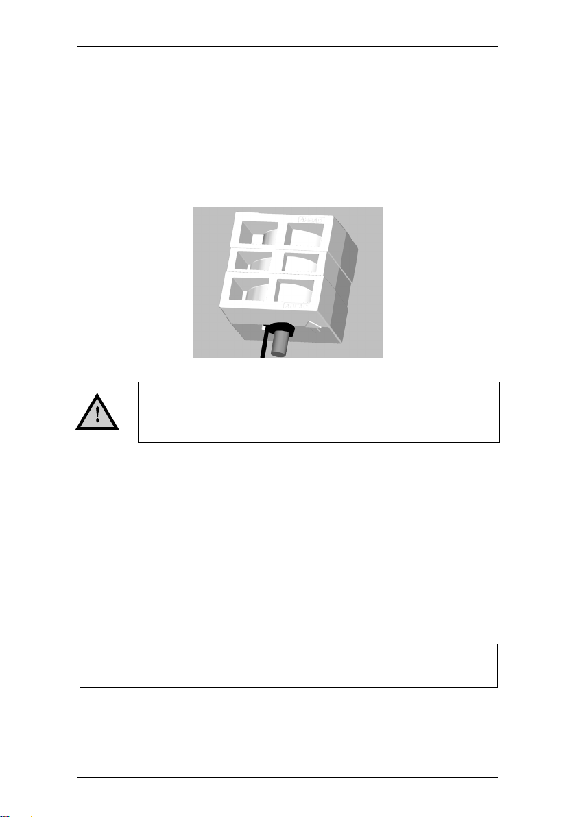
Mount the WSS Remove the protective cap
Do not hit, squeeze or try to
remove the three black rubber
hoods!
To ensure that the display represents the
precise wind direction relative to the ship, the
wind sensor must be aligned correctly. That is,
when mounting the wind sensor, the arrow on
top (and bottom) of the white protection cap
must point ahead towards the stem of the ship
and be parallel with the centre axis of the ship.
Note: An arrow pointing ahead is also found on
the bottom part of the sensor itself.
Do not expose the plastic part of the wind sensor to any torque
when mounting the sensor; the tools used for fastening are only to
be applied on the actual tap.
Protective cap

WSS 500 Series User’s Manual/Installation Note
DEIF A/S Page 7 of 25
Bird avoidance kit
The bird avoidance kit is designed to reduce the risk of birds landing
on the WSS 500 series sensors and thereby interfering with
measurements, or even damaging the sensitive ultrasonic transducer
heads. The black rubber heads are known to attract some birds’
attention because of the click-sound they give off.
The bird avoidance kit is mounted as standard on the WSS 500 series
and can be purchased as an optional extra to mount on previous WSS
versions.
Note that the kit does not provide complete protection against birds,
but especially large sea birds will not be able to land, while small birds
may still be able to squeeze inn. Small birds may interrupt the wind
measurement, but will not be able to damage the sensor.
The shape and location of the spikes has been designed so that the
interference with wind measurements is negligible.
Installation of the kit (retrofit only)
1. Position the metal ring with spikes
around the stainless steel top plate of
the WSS 500 series sensors. Position it
so that the spikes do not block the
direct paths between the three black
rubber heads; see picture.
2. Secure the metal ring using the M3x6
screw provided. It is recommended to
secure the screw from loosening due to
vibrations with a drop of Loctite® super
glue or equivalent (not included in the
kit) and tighten the screw all the way in.
When the kit is mounted on the WSS 500 series sensor,
more snow may be able to accumulate on top of the
sensor, and it may melt slower.
When the WSS 500 series is mounted on a horizontal
mast or surface, it must be raised at least 0.7 metres to
avoid birds sitting next to it – eating the sensor heads!
WSS 500 Series User’s Manual/Installation Note
DEIF A/S Page 8 of 25
3. Check that the kit sits tightly on the WSS 500 series sensor.
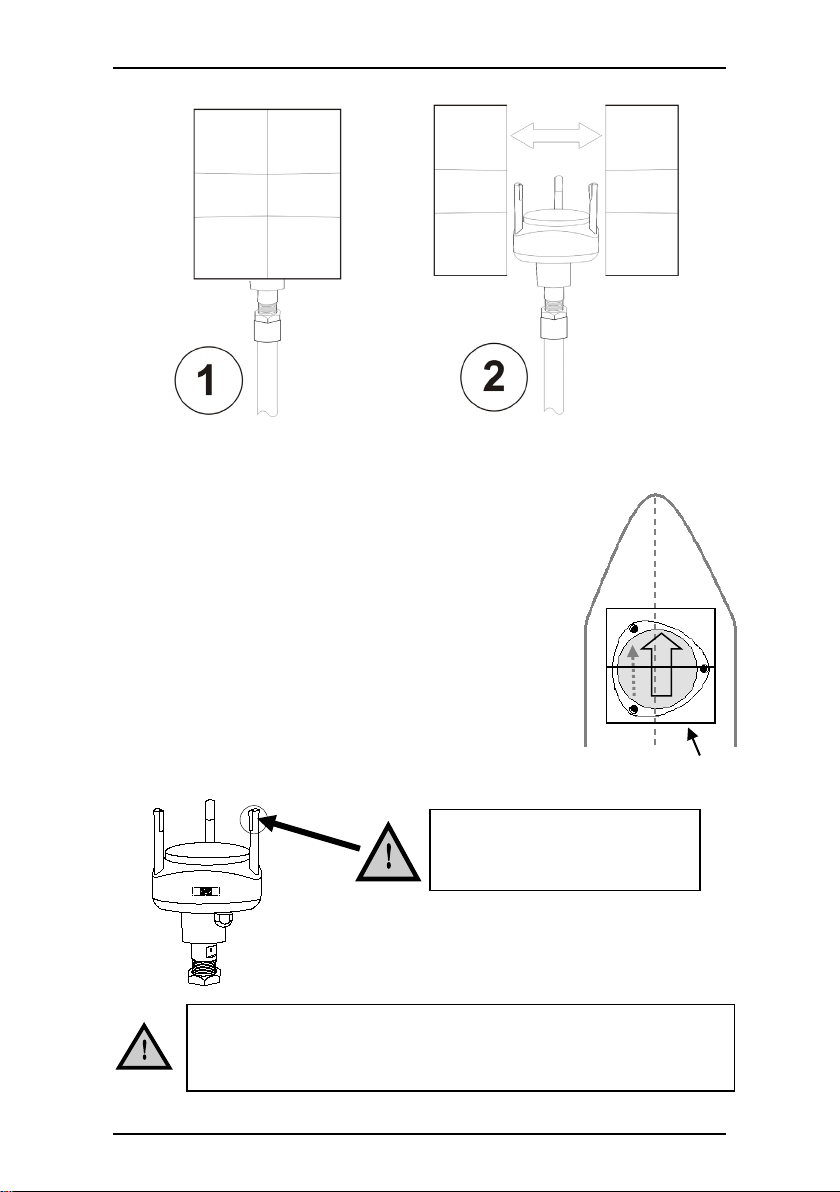
¾” pipe thread:
Outer diameter: 1.04 inch
(26.4 mm), 14 threads per inch
82.4
149.8
198.0
49.5
127.0
114.0
25.0
IMPORTANT!
The stainless steel mounting base on the WSS 500 series
sensor must be connected to earth (for example the steel
hull).

WSS 500 Series User’s Manual/Installation Note
DEIF A/S Page 9 of 25
3. Cable connections
The wind sensor is supplied with 2 metres fixed cable. From factory,
the cable is connected to the sensor via a waterproof gland, and this
must not be replaced by another cable. The cable can be extended by
using the connection box kit or the IP67 connector kit (both optional).
In order to protect the wind sensor and the personnel in the best
possible way from lightning strokes, use a lightning rod installed with
the tip at least one metre above the wind sensor. The lightning rod
must be properly grounded in compliance with all applicable safety
regulations. The wind sensor cable screen and the extension cable
screen must be connected.
For further protection of the cable between the wind sensor and the
connection box, as well as the installation cable between the
connection box and the interface box, it is recommended to use a
metal conduit pipe. If the instrument is installed in a metal panel, this
panel has to be carefully earthed, as well as the instrument itself.
Suitable extension cable is available from DEIF. Alternatively, an
installation cable, for example UL2464 18AWG4C + AE, 4 × 0.75 mm2
screened, can be used. The maximum length is 300 m, and maximum
70 nF capacity between the signal conductors.
WSS 500 series wind sensor cable connections
Cable
colour
Function
Note
Black
Supply
voltage
-
9 to 31 V DC supply for the
WSS 500 series wind sensor
Red
+
Orange
RS-485
comm.
A
Wind speed and direction
data output
Brown
B
Shield
Cable shield
Is connected to the stainless
steel tap inside the WSS.
No supply voltage must be present during installation of the
wind sensor, as this will damage the wind sensor.
WSS 500 Series User’s Manual/Installation Note
DEIF A/S Page 10 of 25
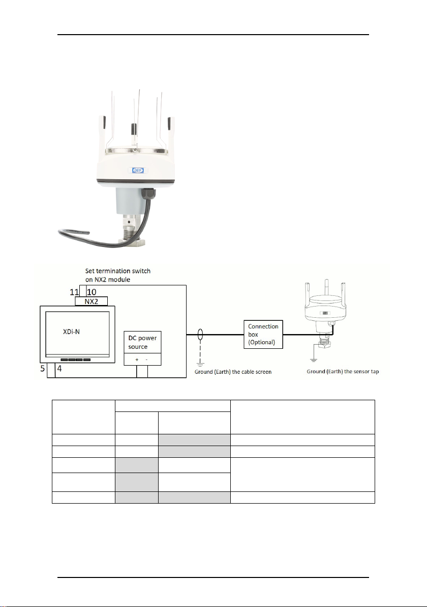
Connecting a WSS 500 series sensor to an XDi-N indicator
WSS 500
series
cable colour
Terminal number
Description
XDi-N
NX2 module
Black (-)
5. 0 V
Aux. voltage: 0 V
Red (+)
4. +24 V
Aux. voltage: +24 V DC
Orange (A)
11. RX/TX2 - A
RS-485 data communication
Termination with 120 Ωinternally
(switchable)
Brown (B)
10. RX/TX2 - B
Screen
Do not connect 1)
1): Cable screen can be connected to ground/earth in case of problems with
electrical noise.

WSS 500 Series User’s Manual/Installation Note
DEIF A/S Page 11 of 25
Set up NMEA input to show wind data
The initial setup of XDi-N is easily performed with the wizard; you will
be guided through the setup of NMEA with automatic scan of NMEA
sentence. Setup of the needed NMEA data is described below.
1. Run Auto scan.
2. Accept and save the found NMEA sentence.
3. XDi-N will return to the NMEA input setup menu.
If no further changes are needed, select Return until the wind
indicator mode is shown on the display.
If offset adjustment is needed, jump to step 4.
Offset to wind direction
4. Select Manual input configuration.
5. Select Wind group, then select Wind direction and find the
offset menu.
6. Offset is entered as degrees with a resolution of 0.1.
An offset of +10 degrees is entered as 100 in the menu.
7. Return to indicator mode where the wind indicator is shown on
the display.
True wind
True wind can either be an actual value, or it can be calculated from
the speed. Which method to use depends on the VI-Setup profile that
has been selected in the setup wizard.
If an indicator with true wind is selected, the following valid NMEA
sentence for true wind can be used: MWV, MWD only for wind speed
true.
True wind can be calculated by the XDi-N, based on the speed from
the following valid NMEA sentence: VHW, VBW, VTG, RMC.
WSS 500 Series User’s Manual/Installation Note
DEIF A/S Page 12 of 25
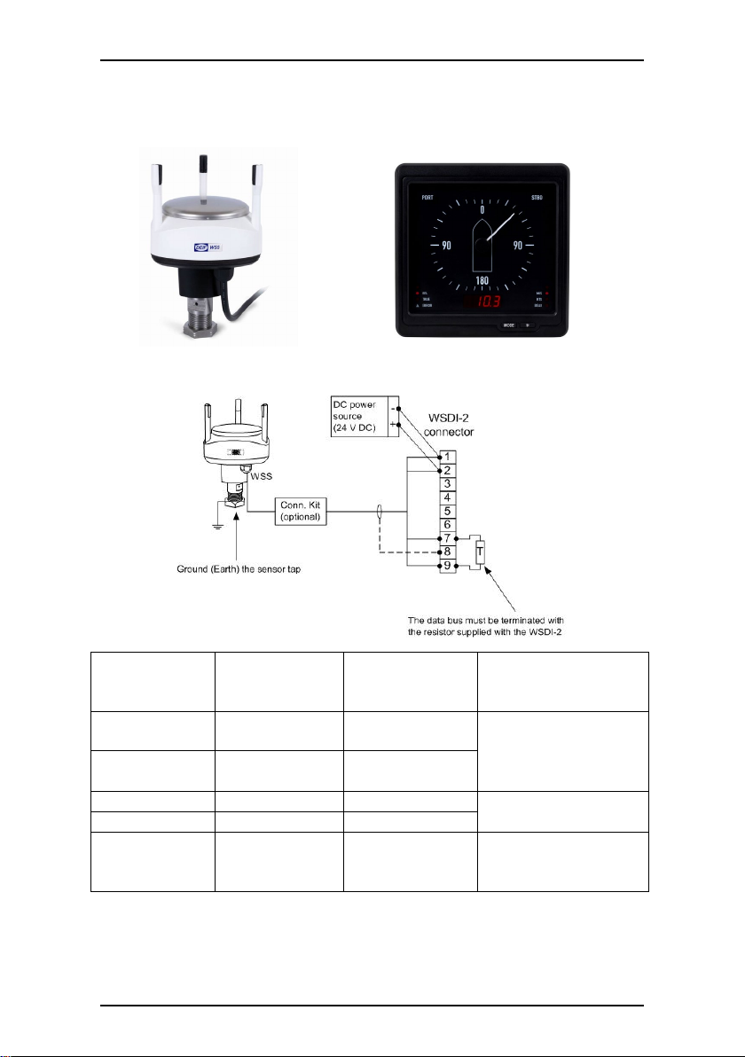
Connecting a WSS or WSS-L to a WSDI-2 display
Wind sensor
WSS/WSS-L
Cable colour
Display WSDI-
2 Terminal
no.:
Description
Comments
Black (-)
1. 0 V
Aux. voltage:
0 V
Aux. voltage to
WSDI-2 and WSS is
parallel-coupled in
the terminal block
Red (+)
2. VCC
Aux. voltage:
+12 or 24 V DC
Orange (A)
7. A
Data A
RS-485 data
communication
Brown (B)
9. B
Data B
Screen
8. (Data GND)
Cable screen
Normally, cable
screen must not be
connected *)
*) The screen should only be connected to WSDI-2 terminal 8 in case
of problems with electrical noise.
WSS/WSS-L WSDI-2

WSS 500 Series User’s Manual/Installation Note
DEIF A/S Page 13 of 25
Connection of other equipment
One standard NMEA0183 input for a VDR or integrated navigation
system can be connected to terminal A and B.
It is recommended to use an NMEA-buffer or NCI-1 if more than one
NMEA input has to be connected. (See also WSDI-2 User’s
Manual/Installation Note no. 4189350032).
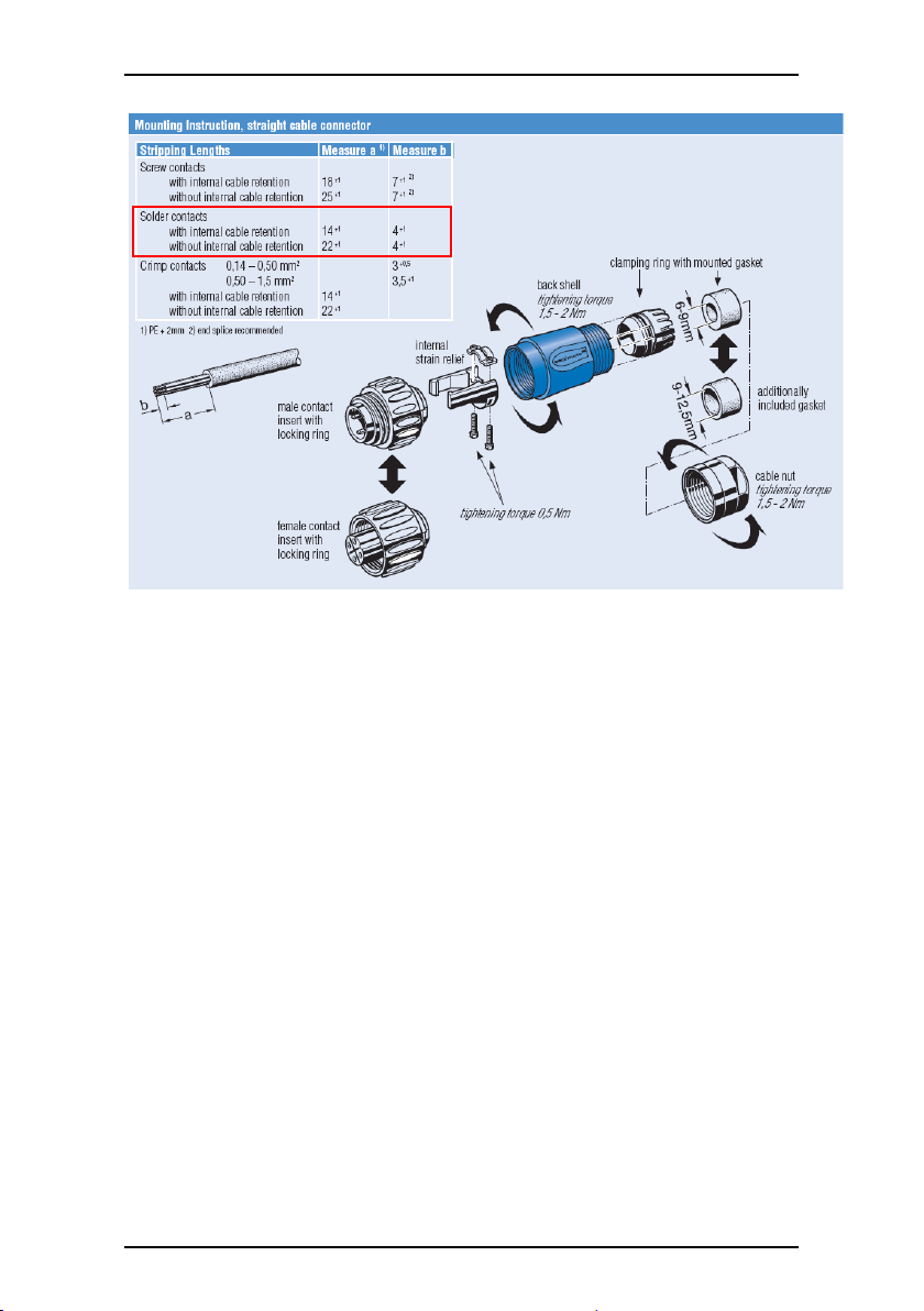
IP67 connector kit assembly (optional)
The connectors must be soldered onto the cable according to the
following instructions:
WSS 500 series
fixed cable
Male connector
Connector
pin no.
WSS 500 series
extension cable
Female connector
Signal
comments
Plug Male 7 pin.
10 22 00 00 52
Plug female 7 pin. 10
22 00 00 53
Screw cap male,
10 29 92 00 02
Screw cap female,
10 29 92 00 03
Black (-)
●
1
Black (-)
●
30 V DC supply
for WSS 500
series
Red (+)
●
2
Red (+)
●
Orange
●
3
Orange
●
RS-485 comm.
from WSS 500
series
Brown
●
4
Brown
●
Screen
●
5
Screen
●
Cable screen
WSS 500 Series User’s Manual/Installation Note
DEIF A/S Page 14 of 25
Measures are in mm.
WSS 500 Series User’s Manual/Installation Note
DEIF A/S Page 15 of 25
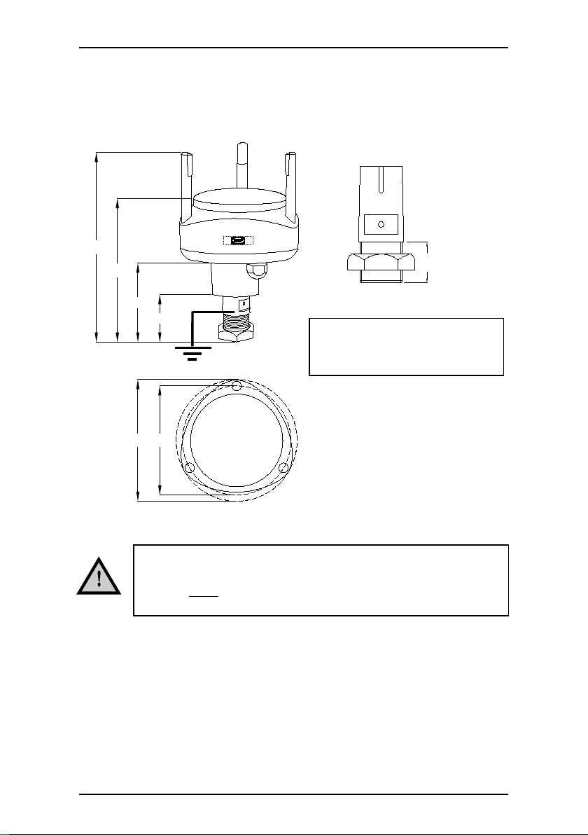
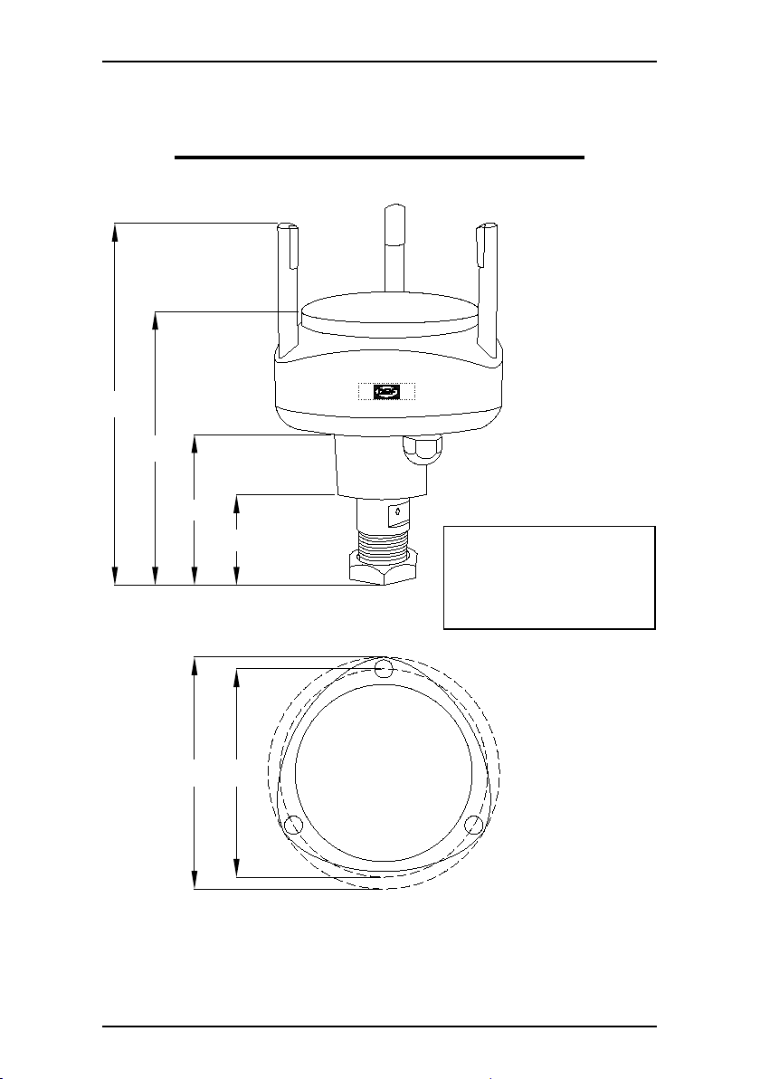
4. Dimensions
82.4
149.8
198.0
49.5
127.0
114.0
¾” pipe thread:
Outer diameter: 1.04 inch
(26.4 mm), 14 threads per
inch.

WSS 500 Series User’s Manual/Installation Note
DEIF A/S Page 16 of 25
Troubleshooting a WSS 500 series/XDi-N installation
Flashing data and symbols on the XDi-N indicate that data is missing.
Using the XDi-N NMEA monitor makes it easy to see the NMEA data
received on the COM ports of the NX2 module.
No.
Fault symptom
on XDi-N
Cause/solution
1
Yellow pop-up box in
upper left corner with
text message
“NMEA S2 Data lost!”
Digital readout and
symbol for wind
direction are flashing.
No data is received from the wind sensor on the connected
port of the NX2 module mounted on the XDi-N.
Start up the NMEA monitor in the service menu1
NMEA data should be received once every second.
If no data is received, check the supply voltage to the
sensor and the cabling.
Check the termination of the system. On the NX2 module
this is possible by means of a switch located beneath the
terminal block.
2
Yellow pop-up box in
upper left corner with
text message
“NMEA S2 Data lost!”
Data for wind speed is
flashing.
There is no valid data for the wind speed.
Start up the NMEA monitor in the service menu1
Check the termination of the system.
On the NX2 module, by means of a switch, it is possible to
set a 120 ohm termination on the RS-485 port.
The switch is located beneath the terminal block.
3
Yellow pop-up box in
upper left corner with
text message
“CAN Data lost!” and
“NMEA S2 Data lost!”
No true wind data is
available, arrow and
true wind data are
flashing.
The message “CAN Data lost!” refers to an internal
calculated value which is not present because input is
missing. If true wind is calculated and no NMEA data of the
speed is available, this message will appear.
Start up the NMEA monitor in the service menu1
Make a scan on dedicated port for speed, or use the scan
for all ports.
If no NMEA data is available, check the cabling at the COM
port of the NX2 module, or check if NMEA speed is present
from the transmitter.
4
Yellow pop-up box in
upper left corner with
text message
“CAN Data lost!” and
“NMEA S2 Data lost!”
No data is flashing.
An indicator with multiple screens is selected, and the
active screen does not present the missing data.
Step through the different screens until a screen with
flashing data appears (up to four screens are possible) and
select this.
Start up the NMEA monitor in the service menu1
If no NMEA data, check transmitter or cabling.
1Accessing the NMEA monitor: See next page.

WSS 500 Series User’s Manual/Installation Note
DEIF A/S Page 17 of 25
5
Yellow pop-up box in
upper left corner with
text message
“CAN Data lost!”
New NMEA data
sentence MWD has
been activated.
Symbol and data for
geographic true wind
are still flashing.
The NMEA sentence MWD has been activated in the
system and is also shown in the NMEA monitor, cabling is
correct, but geographic true wind symbol and data are still
flashing.
Each time a change is made to the NMEA data received,
an auto scan or manual input setup is required.
Perform an auto-scan by entering the NMEA setup menu,
select NMEA input setup and make an auto-scan. Select
Accept selection and save, and then return to indicator
mode.
XDi-N NMEA monitor
The NMEA monitor in the service menu is a powerful tool that makes it
easy to see NMEA data received on the selected COM port. You can
see data from a specific COM port, or from all COM ports
simultaneously.
To access the NMEA monitor: First, access the User menu, then the
Install menu, and subsequently enter the Service menu. The NMEA
monitor is selected in the Service menu.
Menu/function
Button 1
(left)
Button 2
Button 3
Button 4
(right)
User menu
•
•
Install menu
•
•
Access the relevant menu above by pressing the two indicated buttons
simultaneously for 3 to 5 seconds.
The Install menu can only be accessed from the User menu.
WSS 500 Series User’s Manual/Installation Note
DEIF A/S Page 18 of 25
Troubleshooting a WSS/WSDI-2 installation
No.
Fault symptom
on WSDI-2
Cause/solution
1
No light in LEDs,
backlight or display
Aux. voltage is not available (18 to 31 V DC), or the WSDI-
2 is damaged.
2
Orange Error LED is
flashing
The WSDI-2 is defective, contact DEIF or a sales/service
representative.
3
Wind speed is “----“
and direction is not
changing
Cause: There is no valid wind data via RS-485 from the
wind sensor.
Check if the RS-485 port on the WSDI-2 is terminated.
See the WSDI-2 manual:
Check that “input select” is correct (0183 or r.183).
Use the WSDI-2 “Error functions” to find the type of error:
- Communication error (noise or bad connection).
- Error message from WSS sensor received (sensor may
be damaged or defective).
- LED indication for received and transmitted RS-485 data.
If there is no data communication:
- Check voltage from WSDI-2 terminals 7-8 and 9-8, it must
be 2 to 3 V DC on both. If not, the COM port may be
damaged in the WSS or WSDI-2 (lightning stroke,
insufficient lightning protection?), or
- Check the cable connection (broken or short-circuited).
4
Wind speed and
direction is dropping
out periodically
- Bad connection.
- The WSS is not grounded correctly on stainless
mounting tap.
- Heavy electrical noise or insulation error in the ship’s
electrical system (AC or DC).
- The WSS is not able to calculate valid data - snow, ice,
extreme rain or defective sensor head (lightning, bird
attack?).
5
Wind speed and
direction is dropping
out or instable when
outdoor temperature is
dropping below 5 °C
- The sensor is a WSS-L without heating - ice?
- The aux. power supply is not able to supply current
enough to drive the WSS heater. (24 V DC power supply
>2 A is recommended).
6
Wind speed is ”----“
and direction is not
changing when an
additional device
(VDR or Nav system)
is connected in
parallel on the RS-
485 port (A and B)
The added device is most likely overloading the RS-485
bus (only one extra NMEA input is allowed).
Termination on the RS-485 bus is missing.
The connection to the added device is damaged or short-
circuited.
Cable screen is wrongly connected, making a noise loop.
Solution: Use an NCI-1 NMEA converter (out) or an NMEA
buffer to solve the problem.

WSS 500 Series User’s Manual/Installation Note
DEIF A/S Page 19 of 25
7
Wind direction is
wrong
Check that the sensor is aligned correctly. The arrow at the
bottom must point ahead and be parallel with the ship’s
centre line (see chapter 2).
8
No data on the NMEA
output
There must be correct wind data on the WSDI display.
NMEA data may be in the wrong NMEA format (see the
WSDI manual for more details).

WSS 500 Series User’s Manual/Installation Note
DEIF A/S Page 20 of 25
5. Replacement of an old wind sensor
type 879.3c by the WSS 500 series
The special upgrade kit should be used when an existing 879.3c
dynamic wind sensor is to be replaced with a new WSS 500 series
sensor and connected to a display type 879.50/879.521 or WSDI.
The interface box type WSI is needed to translate the RS-485 data
signal from the WSS 500 series into a speed and direction TTL signal
appropriate for the 879.50/879.521 or WSDI display.
Remove the tap for the old sensor 879.3c and mount the new sensor.
Notice that the tap is fixed on the new sensor and is not to be
removed.
Follow the instructions in chapter 2 to mount the new WSS 500 series
sensor correctly.
The existing cable can be used. Before mounting the new sensor
using the existing cable, remember to disconnect the cable from the
wind display and check that the cable is not damaged.
The sensor is equipped with a 2 m cable, this cable is connected to
the existing cable using a junction box (normally already mounted).
WSS 500 series WSI 879.50/879.521 or WSDI
Replacing 879.3c
Table of contents
Other Deif Accessories manuals


