Deif DPS-1 User manual


DPS-1 Installation and operation instructions 4189360002 Rev. C
www.deifwindpower.com Page 2 of 14
Disclaimer
The contents of this document are subject to revision without notice. DEIF A/S shall have no liability for any
error or damages of any kind resulting from the use of this document.
The English version of this document is the original language, and always contains the most recent and up-
to-date information about the product. Translations might not be updated at the same time as the English
version. DEIF A/S does not take responsibility for the accuracy of the translations. The English version
always takes precedence if there is any discrepancy.
Trademarks
DEIF DEIF is a registered trademark of DEIF A/S
All trademarks are the properties of their respective owners.
Copyright
© Copyright DEIF A/S. All rights reserved.

DPS-1 Installation and operation instructions 4189360002 Rev. C Introduction
www.deifwindpower.com Page 3 of 14
Contents
1. Introduction......................................................................................................... 4
1.1 Revision history .................................................................................................4
1.2 Conventions........................................................................................................4
2. Safety precautions ............................................................................................. 5
2.1 Mechanical work.................................................................................................5
2.2 Electrical work....................................................................................................5
3. Package content, tools and handling ............................................................... 6
3.1 Package content.................................................................................................6
3.1.1 Standard package content: .......................................................................6
3.2 Required tools and accessories........................................................................6
3.3 Handling..............................................................................................................6
4. Mechanical mounting......................................................................................... 8
4.1 DIN rail mounting................................................................................................9
4.2 Chassis mounting:.............................................................................................9
5. Electrical connections ..................................................................................... 10
5.1 Connection diagram.........................................................................................10
5.2 General recommendations ..............................................................................11
5.3 Connecting wires to connectors .....................................................................11
6. Operating the DPS-1......................................................................................... 12
6.1 Voltage drop compensation ............................................................................12
6.2 Visual and electrical monitoring......................................................................12
7. Disposal of the DPS-1 ...................................................................................... 13
8. Glossary............................................................................................................ 14
8.1 Terms and abbreviations.................................................................................14
8.2 Units..................................................................................................................14

DPS-1 Installation and operation instructions 4189360002 Rev. C Introduction
www.deifwindpower.com Page 4 of 14
1. Introduction
This document describes how to install and operate the DPS-1. The document is intended for
persons responsible for integration of the DPS-1 in a pitch system, cabinet design, installation
and operation.
For detailed information about specifications and functions of the DPS-1, refer to DPS-1
datasheet.
It is recommended to print this manual in colour in order to get most information out of the
pictures and illustrations.
1.1 Revision history
Apart from editorial changes the following changes have been made in this revision:
Date Revision Changes
2017-06-27 C Total revision of document content.
2012-12-14 B New document
N/A A Not used
1.2 Conventions
The following conventions are used in this document:
Used in document Description
A yellow symbol that illustrates hazard type (this symbol is an example for
general hazard). There are different types such as electrical, chemical and so
on.
Danger! A signal word used to indicate an imminently hazardous situation, which if not
avoided, will result in death or serious injury. (ISO 3864)
Warning! A signal word used to indicate an imminently hazardous situation, which if not
avoided, could result in death or serious injury. (ISO 3864)
Caution! A signal word used to indicate a potentially hazardous situation, which if not
avoided, could result in minor or moderate injury. (ISO 3864)
A blue symbol illustrates a need for mandatory action. In this example read
instructions. Other types of blue symbols exist and always indicate mandatory
action.
A symbol used to draw attention to extra information or an action that is not
mandatory

DPS-1 Installation and operation instructions 4189360002 Rev. C Safety precautions
www.deifwindpower.com Page 5 of 14
2. Safety precautions
Attention
Company policy and local regulations regarding PPE must always be followed, regardless
whether the PPE is shown in this manual or not.
International standards such as IEC 364 and any other relevant international or national
standard regarding safety must be observed. Only qualified personnel who is fully capable
of recognizing, understanding and judging the dangers of the task at hand may perform the
work.
The installation and service of the units should only be handled by qualified persons, who are
conscious of the risks involved.
Ensure that the grounded connection wire of the line is correctly connected to the line input of
the unit. Load and service or measuring setup must be grounded, if possible, in order to
protect the units and the persons working with them.
During normal operation, the persons working with the units must have no contact to
dangerous voltages within the unit.
2.1 Mechanical work
2.2 Electrical work
Use eye, hand and hearing protection
Use protection for eyes, hand and hearing, if the mounting holes for bolts need
to be made during production.
Disconnect power
Ensure that all power is disconnected when working with the DPS-1, except for during
commissioning and service.
Danger!
Risk of burns and electrical shock from short circuit, electrical arc and uninsulated wires.
Commissioning and maintenance work on this device may only be carried out by a qualified
electrician. Observe local regulation when working with electrical components.
When the DPS-1 has been powered, there is a risk of stored energy even when the power
is disconnected. Wait 5 minutes after the power is disconnected and verify zero energy
according to company procedures on the outputs before performing any work.
DPS-1 Installation and operation instructions 4189360002 Rev. C Package content, tools and handling
www.deifwindpower.com Page 6 of 14
3. Package content, tools and handling
3.1 Package content
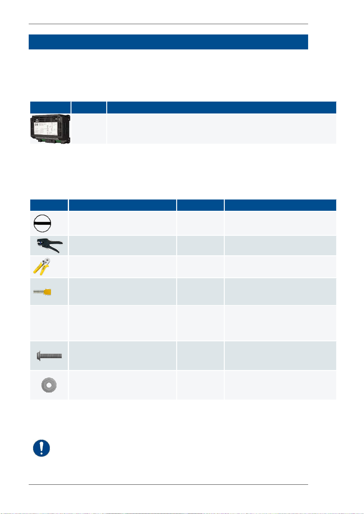
3.1.1 Standard package content:
Quantity
Description
1 DPS-1 power supply
3.2 Required tools and accessories
The following required tools and accessories are not delivered with the DPS-1.
Table 1Required tools and accessories
Tool or accessory Torque Used to
Flat Screwdriver 3 mm wide N/A Connect / disconnect wires.
Wire insulation stripping tool N/A Strip wires insulation
Press tool for ferrules N/A Press ferrules on wires.
Ferrules (recommended) N/A Terminate wires to connectors
(recommended, different size
according to wire size).
Appropriate screwdriver for the
selected 4 mm mounting screws.
Optional, needed if chassis
mounting is selected.
According to
screws spec. Fastening screws (M4).
4 pcs M4 screws
Optional, needed if chassis
mounting is selected.
According to
screws spec. Fasten the DPS-1 to the cabinet.
Length depends on the cabinet
structure.
4 pcs self-locking nut
Optional, needed if chassis
mounting is selected.
According to
screws spec. Fasten the DPS-1 to the cabinet.
3.3 Handling
Attention

DPS-1 Installation and operation instructions 4189360002 Rev. C Package content, tools and handling
www.deifwindpower.com Page 7 of 14
Sufficient care must be taken to protect the terminal against electrostatic
discharges during the installation. Once the unit is installed and connected, these
precautions are no longer necessary.
DPS-1 Installation and operation instructions 4189360002 Rev. C Mechanical mounting
www.deifwindpower.com Page 8 of 14
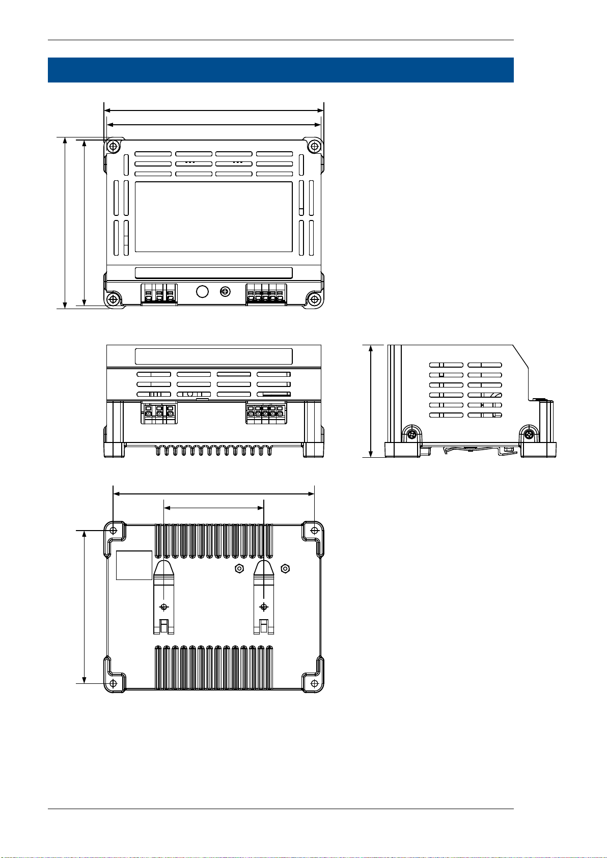
4. Mechanical mounting
150
154
120
70
141
107 116
78.8
Figure 1DPS-1 2405 mechanical drawing
The DPS-1 can be mounted on a 35 mm DIN rail, or by using 4 pcs. 4 mm screws and nuts
(chassis mount).
DPS-1 Installation and operation instructions 4189360002 Rev. C Mechanical mounting
www.deifwindpower.com Page 9 of 14
4.1 DIN rail mounting
For DIN rail mounting just clips the DPS-1 onto the DIN rail (first top, then bottom).
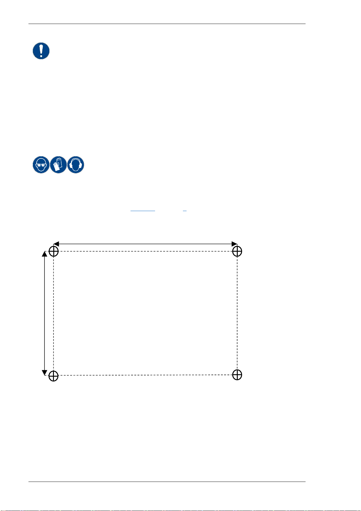
4.2 Chassis mounting:
Use eye, hand and hearing protection
Use protection for eyes, hand and hearing, if the mounting holes for bolts need
to be made during installation.
Drill six ⌀4 mm holes according to Figure 2on page 9and the cabinet drawings for mounting
the DPS-1. Use 4 pcs. 4 mm screws and nuts to mount the DPS-1. Torque according to bolt
specification.
107 mm
141 mm
Figure 2DPS-1 2405 drilling drawing
Info
The vibration, shock and bump specifications apply for chassis mounting only
DPS-1 Installation and operation instructions 4189360002 Rev. C Electrical connections
www.deifwindpower.com Page 10 of 14
5. Electrical connections
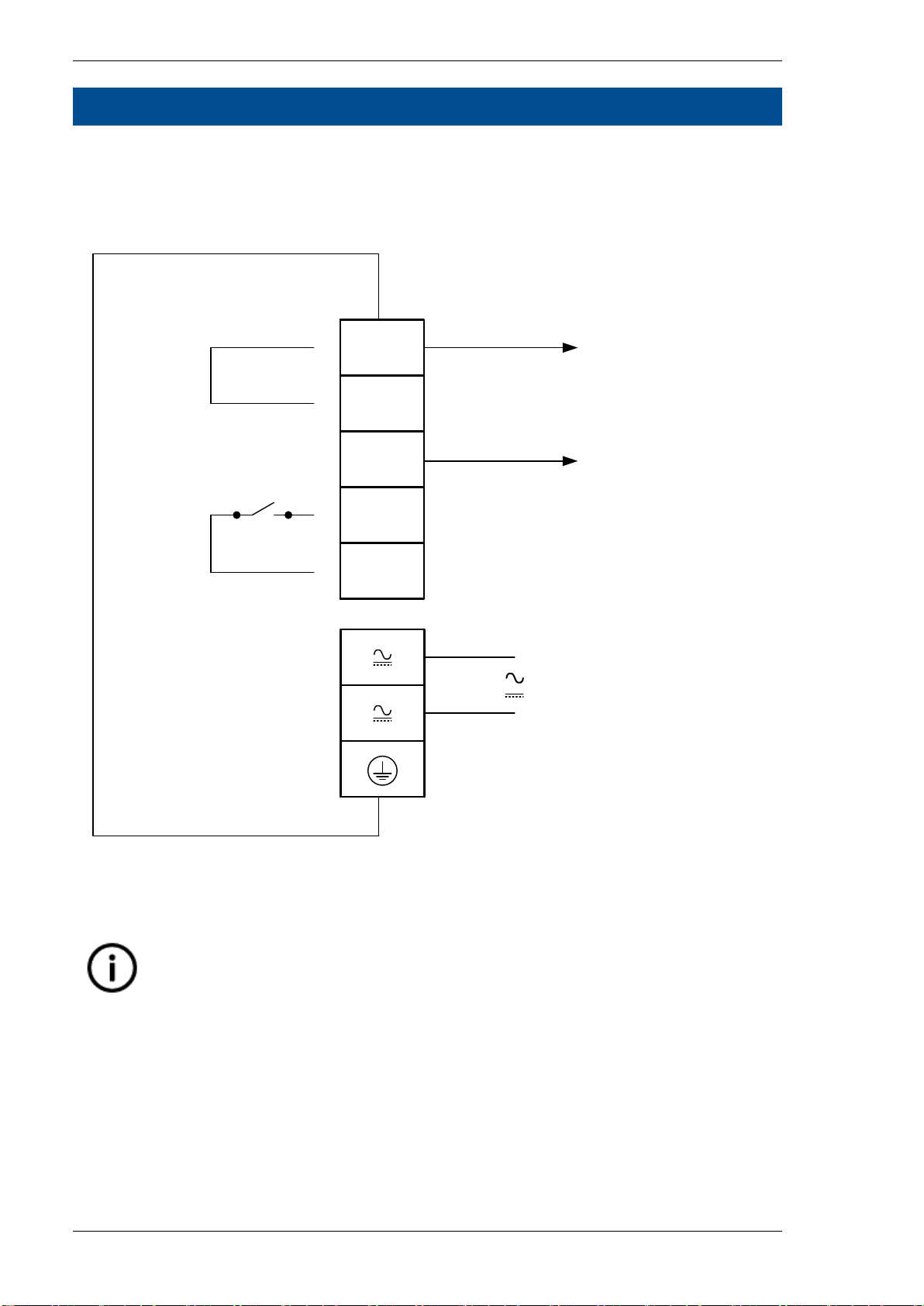
5.1 Connection diagram
The following figure shows the connections to the DPS-1.
- Protective Earth
input
1
2
3
DC OK
DC OK
+
24V DC
-
-
Out
5
4
6
7
8
DPS-1
Figure 3Connection diagram
Connect the wires to the DPS-1 according to the wiring diagram.
Info
Terminals 7 and 8 are internally connected.
Table of contents


