Sargent Electrical Services Ltd. Copyright 2003
Issue1 Page 1of 4 12 January 2005
1ELECTRICALSYSTEM USING PSU 2005
1.1INTRODUCTION
Forthe safeoperation of all electrical equipment withinyourCaravan / Motorhome / TrailerTent /
Folding Camperit isimportant that you read andfully understand theseinstructions. If you areunsure
of any point pleasecontactyourdealer/ distributorforadvicebeforeuse.
YourCaravan/ Motorhome/ TrailerTent / Folding Camperhasbeen fitted withan electrical system
from Sargent Electrical ServicesLtd. andincorporatesthe newPSU2005 power supply. This unit
providesprotection forthe 240v (mains)and 12v equipment, supplies12v power and chargesthe
internal leisurebattery. The electrical system complieswithEN1648-1& -2andBS7671.
1.2MAINS CONNECTION
Foryoursafety itis IMPORTANT that you followtheseconnectionsinstructionseachtime your
Caravan / Motorhome/ TrailerTent / Folding Camperisconnected toamainssupply.
A)Ensure suitabilityofthe Mains Supply. YourCaravan / Motorhome / TrailerTent / Folding
Campershould only be connected toanapprovedsupply that meetsthe requirementsof BS7671.
Inmost casesthe sitewarden will hold informationregarding suitability of supply. If using a
generatoryou alsoneed tocomply withthe requirements/ instructionssupplied withthe generator.
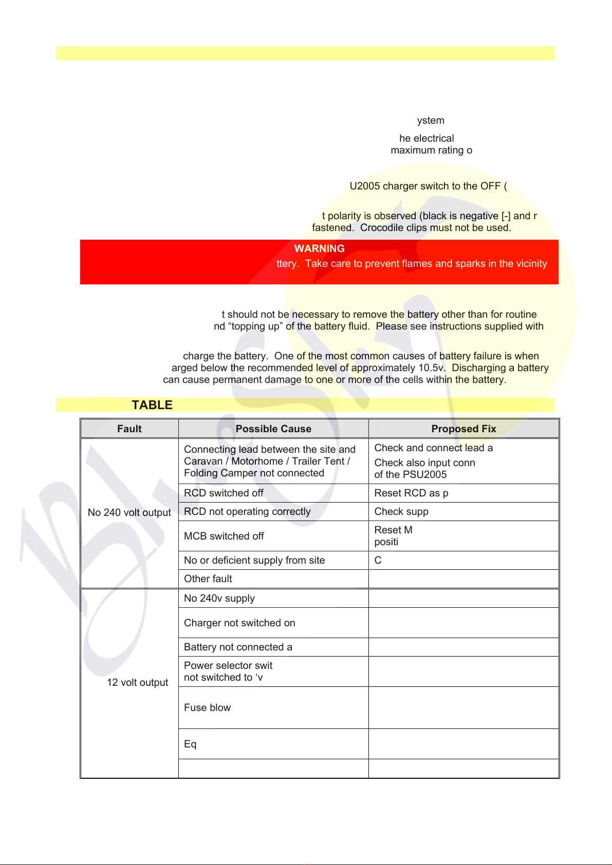
B)Switch thePSU2005unitOFF. Locatethe red power switchon thePSU2005 andensurethe
switchisin theOFF (0)position beforeconnection tothe mainssupply.
C) Connectthe Hook-up Lead. Firstly connect the supplied hook-up lead (orange cablewithblue
connectors) tothe Caravan/ Motorhome/ TrailerTent / Folding Camperand then connect tothe
mainssupply.
D) CheckResidual CurrentDevice operation. Locatethe RCDwithin the PSU2005 and ensurethe
RCDisswitched on (leverin up position). Pressthe ‘TEST’ button and confirmthat the RCDis
turned off (leverin downposition). Switchthe RCDback tothe on position (leverin up position). If
the test button failed tooperatethe RCDseesection1.4.
E)CheckMiniature CircuitBreakers. Locatethe MCB’swithin thePSU2005 (adjacent tothe RCD)
and ensurethey areall in the ON(up)position.
F)Turn the PSU2005 ON. Locatethe red powerswitchon the PSU2005 andturntothe ON(I)
position. The switchwill illuminatewhenturned on.
G)CheckcorrectPolarity.Locatethe ‘ReversePolarity’indicatoronthe PSU2005 and ensurethat
the indicatorisNOTilluminated. If the indicatorisilluminated see section 1.4. Notethat the
reversepolarity indicatoronly works when the red powerswitchisin the ONposition. Also,
reversepolarity indicatormay momentarily flickerasthered powerswitchisturnedon / off, thisis
normal and doesnot indicateafault.
H) Checkoperation ofequipment. It isnowsafetocheckthe operation of the 12v and 240v
equipment.
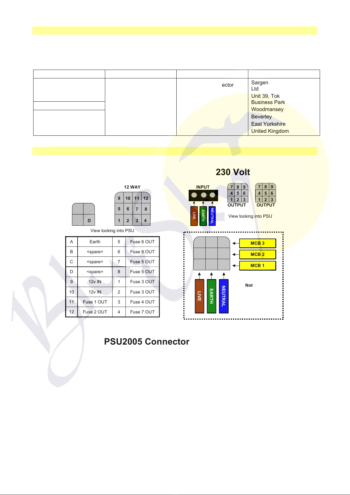
PSU2005Layout PSU2005Specification
MainsInput 230 VoltsAC+/-10%
Frequency50Hz
Output Voltage13.5Voltsnominal
Output Current 12 Ampsnominal
(150 Watts)