manuals.online logo
Brands
  1. Home
  2. •
  3. Brands
  4. •
  5. SECO-LARM
  6. •
  7. Power Supply
  8. •
  9. SECO-LARM EAP-5D1Q User manual

SECO-LARM EAP-5D1Q User manual

®
EAP-3D1Q, EAP-5D1Q,
EAP-3D1MQ, EAP-5D1MQ
Access Control Power Supply, Single Output
Manual
Features:
Input 110~240 VAC, fused at 3.15A
Filtered and electronically regulated output
AC Input and DC output LED status indicators
Adjustable output voltage to compensate for
voltage drop
AC power failure supervision relay
Over-current fuse-protected AC input
12/24 VDC Outputs, field selectable
Battery failure / low battery supervision relay
Built-in back-up battery charger (Batteries not
included)
Automatically switch to backup battery if AC fails

Selectable 2.2kΩ End-of-Line (EOL) resistor for AC
failure and battery failure supervision relays
Selectable delay timer (5sec, 5min, 5h) for AC failure
supervision relay via DIP switch
Automatic shutdown for short-circuit protection
EAP-3D1Q/EAP-5D1Q Only
Heavy-duty steel case with removable cover for easy
access to connections
Ventilation holes to prevent heat buildup
Both have room for two 7Ah batteries (or two 12Ah
batteries for EAP-5D1Q) (Batteries not included)
Knockouts for power connections and optional cam lock
EAP-5D1Q shown
ENFORCER Access Control Power Supply, Single Output
2 SECO-LARM U.S.A., Inc.
1x
Power Supply / Enclos
u
r
e
2x
Screws for the enclosure door
1
x
Cable management clamp
1x
Cable management nut
3x
Wires for backup battery
1x
6ft Power cord with ground wire
1x
Manual
(red, black, white)
1x
Protective plastic bushing for power cable
Model
EAP
-
3D1Q
EAP
-
3D1MQ
EAP
-
5D1Q
EAP
-
5D1MQ
Operating voltage
110~240 VAC
Output voltage
12/24 VDC (selectable)
Output voltage
range (adjustable)
12VDC
12~13
24VDC
23~25
LED Status
indicator
DC
Red=12VDC output, blue=24VDC output
AC
Green, input
Current rating
3A@12VDC, 1.5A@24VDC
5A@12VDC, 2.5A@24VDC
Supervision relays
EOL: Selectable ON (2.2k
Ω) or OFF, 3A@24VDC dry relay output
AC Input fuse rating
3.15A
AC Power cord
6ft (1.8m)
n/a
6ft (1.8m)
n/a
Operating humidity
85%
maximum
Operating temperature
-
4°~149° F (
-
20°~65° C)
Dimensions 121/8"x121/4"x39/16"
(308x311x90 mm)
5
1
/
2
"x4
3
/
4
"x1
9
/
16
"
(140x120x39 mm)
14
13
/
16
"x14
5
/
16
"x4
1
/
8
"
(377x363x105 mm)
5
1
/
2
"x4
3
/
4
"x1
9
/
16
"
(140x120x39 mm)
Weight
9
-
lb 13
-
oz (4.4
5kg)
9
.
9
-
oz
(280g)
10
-
lb 11
-
oz (4.85kg)
11.3
-
oz (320g)
Specifications:
Overview:
Parts List*:
ON OFF
Backup battery
terminal
DC Output terminal
AC Input LED
status indicator
AC Failure
supervision
relay output
Battery failure / low
battery supervision
relay output
110~240
VAC Input
terminals
Battery presence / low
battery monitor DIP
switch (default ON)
End-of-line (EOL)
2.2kΩ resistor DIP
switch (default ON)
AC Failure delay
timer DIP switch
(default 5s)
12/24 VDC
Output selection
slide switch
(default, 12VDC)
Power
switch
(default
OFF)
DC Output voltage
adjustment
potentiometer
+
–
ON
1
2
ON
1 2
Vol. Out.
ON OFF
24V 12V
AC FAIL Time
S1 S2
5s
ON ON
5m
ON OFF
5H
OFF
OFF
ON
1 2
LB Mode
Both
ON
Both
OFF
PRESENT
FAIL
S1
S2
ON
OR
OFF
2.2K
DC Output LED
status indicator*
red=12V, blue=24V
EAP-5D1Q/EAP-5D1MQ shown
*Built-in output overload / short-circuit protection – If an overload occurs, the motherboard's output voltage output will drop.
The voltage drop will depend on the extent of the overload. The greater the overload the greater the voltage drop. If the
overload is extensive, the voltage output will become intermittent and the red LED will start flashing. When the overload is
removed, the mainboard will automatically restart normal output. If an output short-circuit occurs, the motherboard will
automatically shut the output down and the red LED will turn off. When the short-circuit is removed, the motherboard will
automatically come back on line.
*EAP-3D1MQ / EAP-5D1MQ includes power supply board, backup battery wires, and manual only
ENFORCER Access Control Power Supply, Single Output
SECO-LARM U.S.A., Inc. 3
Installation:
IMPORTANT
:
The ENFORCER Power Supply is not waterproof or weatherproof. Therefore, it must be
mounted indoors where it will not be exposed to rain or other moisture.
Installation must be done by qualified personnel, and should conform to local and all
other applicable codes.
1. Choose a mounting location out of sight and protected from moisture and weather, but easily accessible
for future servicing.
NOTE: Make sure the space where the enclosure is to be mounted has adequate ventilation. Otherwise,
heat buildup inside the enclosure could damage the electronic parts.
2. Locate the enclosure mounting holes. Using these holes as a template, mark the location of the 4 screws
on the wall with a pencil.
3. Thread the AC power cord through the protective plastic power cord bushing and then through the power
cord hole in the enclosure, snapping the bushing into place. Secure the power cord with the cable
management clamp.
4. Attach to the wall by first screwing in two 3/16" x 1" (4x26 mm) upper screws using plastic wall anchors if
needed (both not included) until the gap between the wall and the screw head is approximately 1/4
" (6mm).
5. Hang the enclosure on the two upper screws using the enclosure's upper screw holes and adjust the
proper location of the enclosure. Screw in the tw
o lower screws. Then securely fasten the upper and lower
screws.
6. Run wires from the access control device or accessory to the power
supply. The enclosure has knock-outs on the side, top, bottom, and
rear panels for running cables. Punch out the appropriate knock-outs
(see Fig. 1).
7. Set the desired DC output voltage (12 or 24 VDC) of the power
supply using the sliding switch (see "Overview," pg. 2). The default
voltage output setting is 12VDC.
8. Temporarily connect the AC power (110~240 VAC) to the "AC INPUT" terminal block of the power supply
by following the terminal labels (i.e. "A" for active wire, "E" for ground wire and "N" for neutral wire, see
"Overview," pg. 2). Move the AC power switch to ON. The AC power indicator LED should turn green and
the DC output indicator LED should turn red (blue, if DC output voltage switch is set for 24VDC)
to indicate
the power supply unit is working properly.
9. Check the output voltage reading of the power supply's DC output terminal block marked "- DC
+" to make
sure it is within the normal range (see "Overview," pg. 2). The default output voltage of the power supply
should be about 12.6VDC at no load when set at 12VDC, and about 25VDC at no load when set at
24VDC. After checking, disconnect the AC input power.
10. Connect the power input wires of the access control device or accessory to the power supply's DC output
terminal block (see "Overview," pg. 2). OBSERVE CORRECT POLARITY.
IMPORTANT NOTES/WARNINGS:
a. To avoid risk of electrical shock, the ground terminal of the "AC INPUT" MUST be connected to
earth via the power cord.
b. Maximum total current connected to the power supply terminal must not exceed the power supply's
total current capacity (5A@12VDC and 2.5A@24VDC).
c. Be sure to check the output voltage reading of the power supply as stated in point 6
above, and double
check the specified operating voltage of each device before connecting it to the power supply to avoid
potential damage.
d. Use at least 18-gauge wires to minimize voltage drop. The thinner the wire, the greater the voltage
drop.
e. Keep power limited wiring separated from non-power limited wiring (AC input, battery wiring) by a
minimum distance of 1/4" (7mm) and use separate knockouts in the enclosure.
Fig. 1
Cable and power
knock-outs
K
nock
-
out
for
optional cam lock
ENFORCER Access Control Power Supply, Single Output
4 SECO-LARM U.S.A., Inc.
Installation (Continued):
IMPORTANT:
Users and installers of this product are responsible for ensuring that the installation and configuration
of
this product complies
with all national, state, and local laws and codes. SECO-LARM will not be held responsible for the use of this product in vi
olation of any current
laws or codes.
California Proposition 65 Warning:
These products may contain chemicals which are known to the State of California to cause cancer and
birth defects or other reproductive harm. For more information, go to www.P65Warnings.ca.gov.
WARRANTY:
This SECO
-
LARM product is warranted against defects in material and workmanship while used in normal service for
one (1) year from the date of sale to the original customer. SECO-
LARM’s obligation is limited to the repair or replacement of any defective
part if the unit is returned, transportation prepaid, to SECO-
LARM. This Warranty is void if damage is caused by or attributed to acts of God,
physical or electrical misuse or abuse, neglect, repair or alteration, improper or abnormal usage, or faulty installation, or if for any o
ther reason
SECO-LARM determines that such equipment is not operating properly as a result of causes other than defects in material
and workmanship.
The sole obligation of SECO-LARM and the purchaser’s exclusive remedy, shall be limited to the replacement or repair only, at SECO-
LARM’s
option. In no event shall SECO-LARM be liable for any special, collateral, incidental, or consequent
ial personal or property damage of any kind
to the purchaser or anyone else.
NOTICE:
The SECO
-
LARM policy is one of continual development and improvement. For that reason, SECO
-
LARM reserves the right to
change specifications without notice. SECO-LARM is also not responsible for misprints. All trademarks are the property of SECO-
LARM
U.S.A., Inc. or their respective owners. Copyright © 2023 SECO-LARM U.S.A., Inc. All rights reserved.
11.
Reconnect the AC power and check the DC output voltage reading at the end of the wire pairs where it i
s
to be connected to the device. If the output voltage reading falls below the minimum voltage requirement
of the device, use a small screwdriver to carefully turn the potentiometer marked "VR1" located on the
PCB. Turn clockwise to increase the voltage and counterclockwise to decrease the voltage (see
"Overview," pg. 2).
IMPORTANT NOTES:
a. Do not adjust the potentiometer unless absolutely necessary. Adjusting the potentiometer will alter the
default factory setting.
b. An output voltage in excess of the specified voltage level of the device may cause damage.
12. Once the desired DC output voltage is achieved, connect the wire pairs to the device.
13. Connect a visual or audio indicator device (such as siren or strobe light) to the AC-failure and battery-
failure / low battery supervision relays if needed (see "Overview," pg. 2). Use between 22AWG to 18AWG
wire size.
Programmable Features
a. AC-failure Relay Output Delay Timer — Program the AC-failure relay delay timer at 5sec, 5min or 5h
using the DIP switch (see "Overview," pg. 2). The default setting is at 5sec.
b. 2.2K Ohm End-of-Line (EOL) Resistor — The end-of-line 2.2kΩ resistor for AC-failure relay and
battery-failure / low battery supervision relays (3A@24VDC, dry relay) can be activated independently
using the DIP switch (see "Overview," pg. 2). The default setting is ON.
c. Battery Presence and Low Battery Monitor — When the LB MODE DIP switches are in the ON
position, the power supply will monitor the battery to verify if it has sufficient voltage to run the power
supply in case of AC power failure. Selecting "OFF" will stop monitoring of battery status and will
charge battery continuously. It can take up to 5 minutes to alert you of a battery failure. The length of
time the system will run will be limited by the overall capacity and the age of the batteries and the
amount of load being drawn off the power supply. The
default setting is ON.
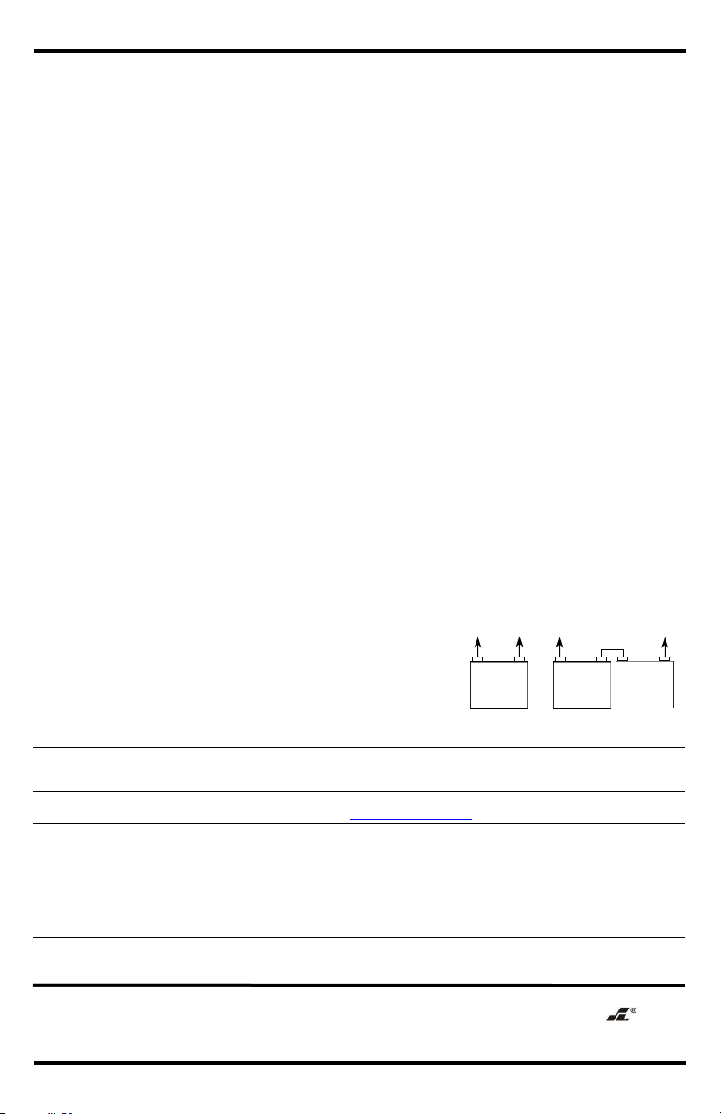
14. Connect the backup battery to the backup battery terminal
(see Fig. 2 and "Overview," pg. 2).
15. Close the enclosure door and secure it with either the
provided machine screws or an optional cam lock.
SECO-LARM
® U.S.A., Inc.
16842 Millikan Avenue, Irvine, CA 92606
Website:
www.seco
-
larm.com
Phone: (949) 261-2999 | (800) 662-0800 Email: sales@seco-larm.com
PITSW1
Order Part#
764
-
017
-
6
%
MI_EAP-xD1QUS_230814.docx
Fig. 2
12VDC
24VDC
–
+
12VDC
Battery
–
+
12VDC
Battery
–
+
12VDC
Battery

This manual suits for next models

3

Other SECO-LARM Power Supply manuals

SECO-LARM SLI Enforcer EAP-1D1Q User manual

SECO-LARM

SECO-LARM SLI Enforcer EAP-1D1Q User manual

SECO-LARM Enforcer SB-L10V1-20Q User manual

SECO-LARM

SECO-LARM Enforcer SB-L10V1-20Q User manual

SECO-LARM ENFORCER EVP-1SD2P4UL User manual

SECO-LARM

SECO-LARM ENFORCER EVP-1SD2P4UL User manual

SECO-LARM Enforcer EAP-5D1 User manual

SECO-LARM

SECO-LARM Enforcer EAP-5D1 User manual

SECO-LARM Enforcer EAP-5D1 User manual

SECO-LARM

SECO-LARM Enforcer EAP-5D1 User manual

SECO-LARM Enforcer EVP-124M6-P16 User manual

SECO-LARM

SECO-LARM Enforcer EVP-124M6-P16 User manual

SECO-LARM ENFORCER PH-U1612-PULQ User manual

SECO-LARM

SECO-LARM ENFORCER PH-U1612-PULQ User manual

SECO-LARM Enforcer EV-1223B12 User manual

SECO-LARM

SECO-LARM Enforcer EV-1223B12 User manual

SECO-LARM Enforcer ST-1206-1.5A User manual

SECO-LARM

SECO-LARM Enforcer ST-1206-1.5A User manual

SECO-LARM EVP-124D4-P9 User manual

SECO-LARM

SECO-LARM EVP-124D4-P9 User manual

SECO-LARM ENFORCER PC-U0405-PULQ User manual

SECO-LARM

SECO-LARM ENFORCER PC-U0405-PULQ User manual

SECO-LARM Enforcer Voltage Booster ST-HB105-TTQ User manual

SECO-LARM

SECO-LARM Enforcer Voltage Booster ST-HB105-TTQ User manual

SECO-LARM Enforcer Video EVP-1SA4P4UL User manual

SECO-LARM

SECO-LARM Enforcer Video EVP-1SA4P4UL User manual

Popular Power Supply manuals by other brands

EVGA SuperNOVA 650P2 PLATINUM Series user manual

EVGA

EVGA SuperNOVA 650P2 PLATINUM Series user manual

Stahl Series 9160 operating instructions

Stahl

Stahl Series 9160 operating instructions

Rosslare PS-C18 installation manual

Rosslare

Rosslare PS-C18 installation manual

Yamaha PW3000M owner's manual

Yamaha

Yamaha PW3000M owner's manual

OCELOT GAMING OPS650 manual

OCELOT GAMING

OCELOT GAMING OPS650 manual

TTI QL II Series Service manual

TTI

TTI QL II Series Service manual

Forcefield DUALGIZER DG1 Installation & operation instructions

Forcefield

Forcefield DUALGIZER DG1 Installation & operation instructions

Antec EARTHWATTS 650 GREEN user manual

Antec

Antec EARTHWATTS 650 GREEN user manual

Thermo Scientific EC300XL Operating and maintenance manual

Thermo Scientific

Thermo Scientific EC300XL Operating and maintenance manual

Nordson Standard iControl instruction sheet

Nordson

Nordson Standard iControl instruction sheet

Huawei UPS5000-E Series user manual

Huawei

Huawei UPS5000-E Series user manual

Palmer WTP B40 user manual

Palmer

Palmer WTP B40 user manual

NF BP4610 instruction manual

NF

NF BP4610 instruction manual

Insignia NS-PCW4508 user guide

Insignia

Insignia NS-PCW4508 user guide

Moeller SN 4-024-DI7 installation instructions

Moeller

Moeller SN 4-024-DI7 installation instructions

Aktakom APS-1303 user manual

Aktakom

Aktakom APS-1303 user manual

Agilent Technologies 6030A Service manual

Agilent Technologies

Agilent Technologies 6030A Service manual

Alpha Technologies SP0123 User manual and technical specifications

Alpha Technologies

Alpha Technologies SP0123 User manual and technical specifications

manuals.online logo
manuals.online logoBrands
  • About & Mission
  • Contact us
  • Privacy Policy
  • Terms and Conditions

Copyright 2025 Manuals.Online. All Rights Reserved.