Deif TAS-331DG Instructions and recipes
DEIF A/S Tel.: (+45) 9614 9614
Frisenborgvej 33, DK-7800 Skive Fax: (+45) 9614 9615
Denmark E-mail: deif@deif.com
DEIF A/
S
Installation and start up instructions
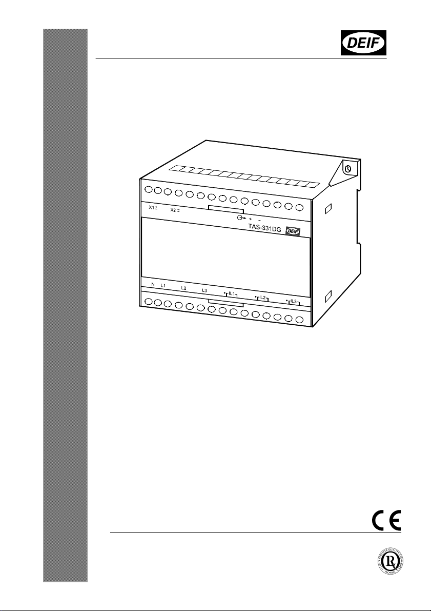
TAS-331DG
Selectable AC transducer
4189300008G (UK)
Watt or var transducer
Supply and measuring voltage up to 690V
Configuration via PC-interface possible
35 mm DIN rail or base mounting
Page
2
of
8
Tel.:
(
+
45) 9614 9614
Fax: (
+
45) 9614 9615
E
-
mail: [email protected]
Description
TAS-331DG is a micro controller based power transducer with 1 analog output for
measurement of Watt or var. The transducer holds no mechanical moving parts like
potentiometers and therefore the calibration stability is excellent.
Label
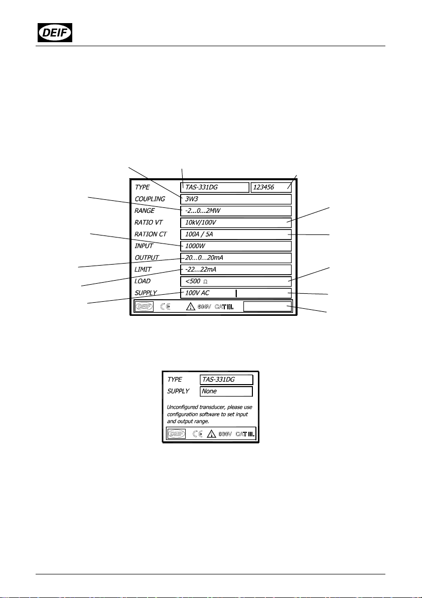
The configured transducer is provided with a label with the following data:
The un-configured transducer is provided with a label with the following data:
Type designation DEIF´s order ack. no. To be stated
when contacting DEIF
Coupling
Measuring range
Primar
y
values
Output range
Output limited
to ±22mA
Auxiliary voltage
Condition of external
voltage transformer
Condition of external
current transformer
Max output load
current output
Min output load
voltage output
Distributor´s ID
Other information
If special product
Measuring range
Secondary values
DEIF´s order ack. no. can be
found on a paper label on the
transducer box.
About configuration see special
manual.

Installation and start up instructions, TAS-331DG
4189300008
G
(UK)
Mounting instructions
TAS-331DG is designed for
panel mounting, being
mounted on a 35 mm DIN rail,
or by means of two 4-mm
screws.
Weight: Approx. 0.650 kg
The design of the transducer makes mounting of it close to similar equipment
possible, however make sure there is min. 50 mm between the top and bottom of the
transducer and other equipment.
The DIN rail must always be placed horizontally when several transducers are
mounted on the same rail.
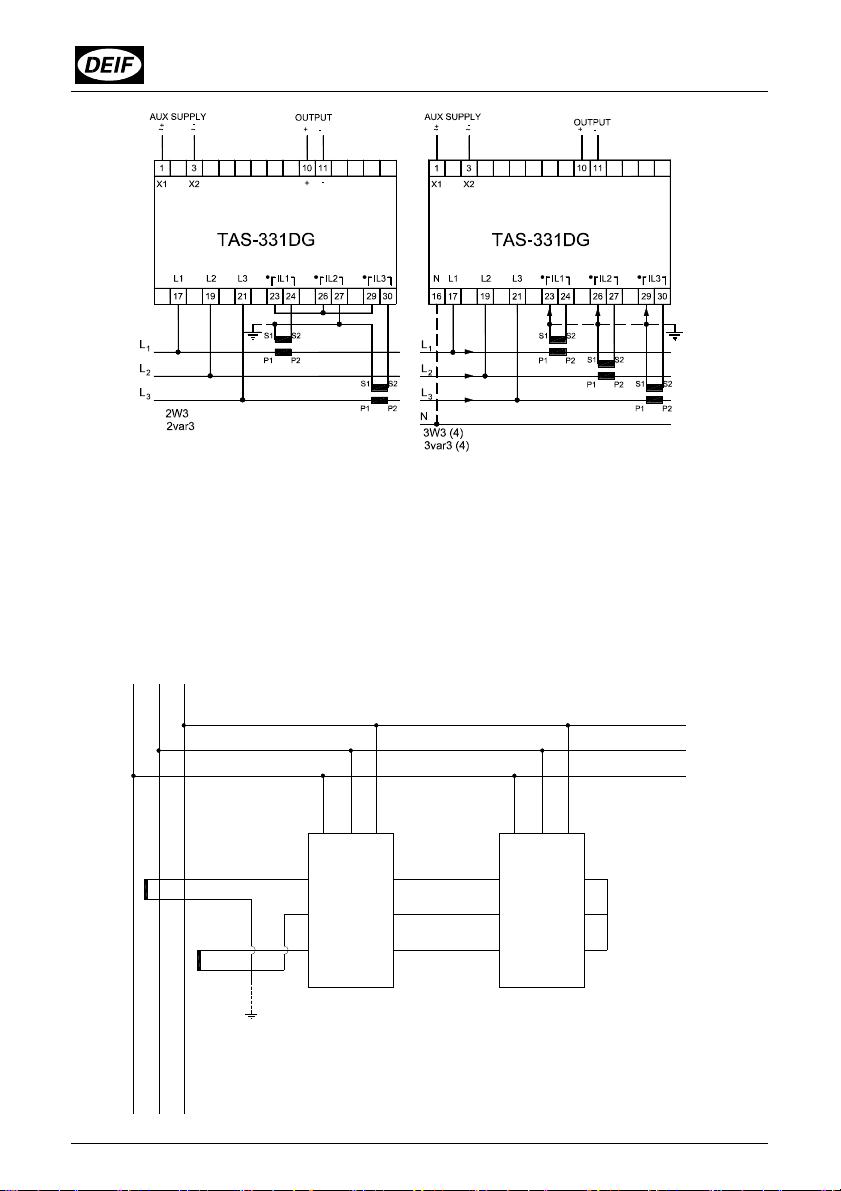
Connection diagram
With voltages above 480V phase-phase.
The secondary side of the current transformer must be connected
to earth. Alternatively a double insulated current transformer can
be used.
Page
4
of
8
Tel.:
(
+
45) 9614 9614
Fax: (
+
45) 9614 9615
E
-
mail: [email protected]
It is not necessary to protect the measuring voltage inputs. But it is recommended to
use a 2A fuse for the supply input (terminals 1 and 3).
The transducer is protected against ESD (electrostatic electricity), and further special
protection against this during the mounting of the transducer is not necessary.
The below diagram illustrates how to connect a TAS-331DG in 2W3 configuration with
a TAS-331DG in 2var3 configuration.
L12
L3
L
17 19 21
24 23
27 26
30 29
TAS - 331DG
2W3
S1
S2
S
S1
2
2var3
TAS - 331DG
30
27
29
26
24 23
1917 21

Installation and start up instructions, TAS-331DG
4189300008
G
(UK)
The voltage inputs are connected as follows, if the current transformers are placed in
other phases than indicated in the above diagram:
2W3/2var3
External current transformer Connect
connected to
L1 (23 + 24) and L2 (29 + 30)
L1
to term. No. 17
L3
to term. No. 19
L2
to term. No. 21
connected to
L2 (23 + 24) and L3 (29 + 30)
L2
to term. No. 17
L1
to term. No. 19
L3
to term. No. 21
Couplings 1W/1var and 1W4/1var4: Connect terminal No. 17 to the phase to
which the external current transformer is connected.
1W3/1var3:
External current transformer Connect
- connected to L2 L2
to term. No. 17
L3
to term. No. 19
L1
to term. No. 21
- connected to L3 L3
to term. No. 17
L1
to term. No. 19
L2
to term. No. 21
Connection/set up
The transducer is equipped with a red LED for indication of wrong phase connection
or errors in the calibration / configuration. This LED is placed under the front plate.
The function of the LED are as follows:
Constant light. The wiring may be wrong. There is not equal power direction on all
phases. There must be signal on all inputs to ensure correct testing and current flow
in all phases. Note this function is only activated in coupling 2W3, 2var3 and 3W3(4),
3var3(4).
Fast pulse 5Hz. The calibration data are corrupted. Contact DEIF.
Slow pulse 1Hz. The configuration data are wrong or corrupted. Make a re-
configuration or contact DEIF. About configuration see special manual.
Page
6
of
8
Tel.:
(
+
45) 9614 9614
Fax: (
+
45) 9614 9615
E
-
mail: [email protected]
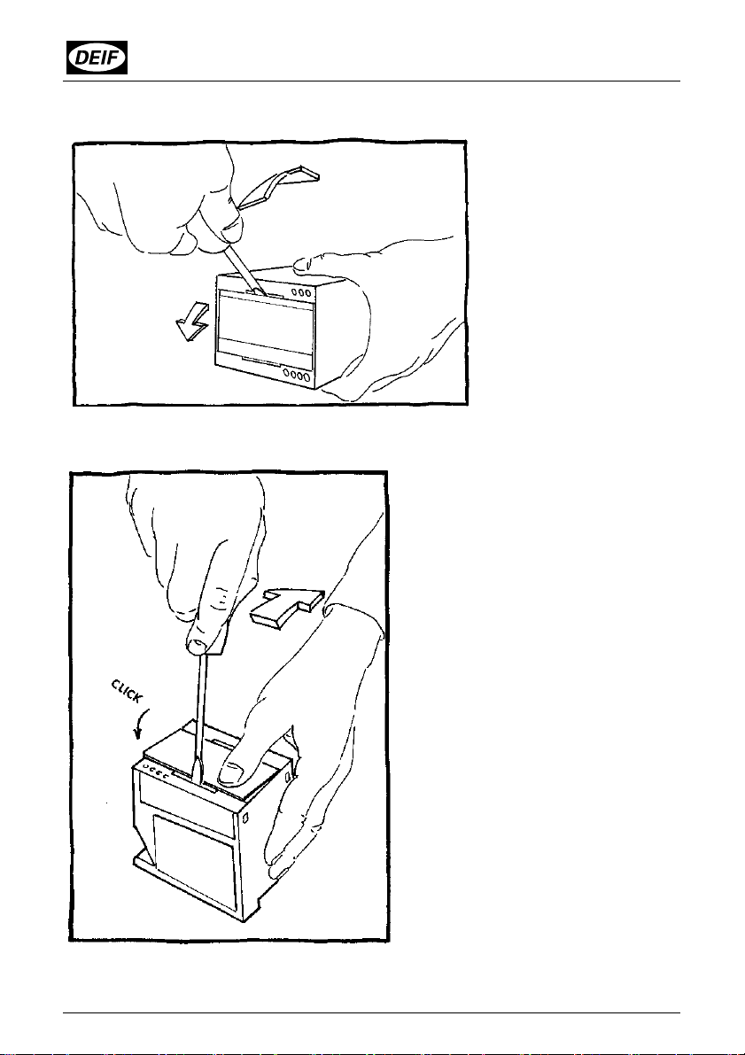
Opening of the unit
Mounting of the front panel
The front panel is
removed by means of a
screwdriver. The front
panel may be loosened
in the right side first and
is then totally demounted
by moving the screw-
driver towards left.
Press with a screwdriver as
indicated by the arrow and press
the front panel down with your
thumb, simultaneously. It is
recommended that one side of
the front panel snaps into place
before the other.

Installation and start up instructions, TAS-331DG
4189300008
G
(UK)
Technical specifications
Accuracy: Class 0.5 (-10…15…30…55°C) according to IEC 688
Influence, phase angle: ≤ ±0.75°
Meas. current (In) 0.75/1.5/3.0/6.0A Meas. range: 0…200% In
I
n can be set between 0.375…6A
Overload, currents: 20A max., continuously
75A max. for 10 s
240A max. for 1 s
Load: Max. 0.5VA per phase
Meas. voltage (Un): 73/140/254/400V phase to neutral Meas. range: 30…120%Un
U
n can be set between 57…400V
127/240/440/690V phase to phase Meas. range: 30…120%Un
U
n can be set between 100…690V
Overload, voltages: 1.2 x Un max., continuously, 2 x Un max. for 10 s
Load: Min. 480k
Frequency range: 30…45…65…80Hz
Note: For fundamental frequency (1. harmonic) outside 20Hz
…80Hz the input is fixed to 0
Indication: Red LED function:
(The LED is located behind the front plate)
Incorrect wiring = constant light, only active for coupling 1W3,
2W3, 3W3(4) and 1var3, 2var3, 3var3(4). Check at power up,
in case of doubt disconnect supply and reconnect
Calibration error = flash frequency 5Hz
Configuration error = flash frequency 1Hz
Output: 1 analog output
Standard range: Output (0...100%):
0...1mA, 0...5mA, 0...10mA, 0...20mA, 0...1V, 0...5V, 0...10V
Output (10...100%):
0.1...1mA, 0.5...5mA, 1...10mA, 2...20mA, 0.1...1V, 0.5...5V,
1...10V
Output (20...100%):
0.2...1mA, 1...5mA, 2...10mA, 4...20mA, 0.2...1V, 1...5V,
2...10V
Output (-100...0...100%):
-1...0...1mA, -5...0...5mA, -10...0...10mA, -20...0...20mA,
-1...0...1V, -5...0...5V, -10...0...10V
Other ranges possible

Page
8
of
8
Tel.:
(
+
45) 9614 9614
Fax: (
+
45) 9614 9615
E
-
mail: [email protected]
Limit: Max. ±120% of nominal output
Output load: Burden if current output: Max. 10V (max. 1k)
Burden if voltage output: Max. 20mA
Output cable: Max. length 30m
Ambient temperature: -10…55oC (nominal)
-25…70oC (operating)
-40…70oC (storage)
Temperature
coefficient: Max. ±0.2% of full scale per 10°C
Response time: Coupling 2W3/2var3, 3W3/3var3, 3W4/3var4 <225ms,
typically 200ms
Coupling 1W/1var, 1W4/1var4 <150ms, typically 125ms
Coupling 1W3/1var3 <125ms, typically 100ms
Ripple: Twice the class index (peak to peak measurement) according
to IEC 688
Galvanic separation: AC aux. supply models:
Between inputs, outputs and aux. supply:
3750V-50Hz-1 min.
DC aux. supply models:
Between inputs and outputs: 3750V-50Hz-1 min.
Between inputs and supply: 3750V-50Hz-1 min.
Between supply and outputs: 1500V-50Hz-1 min.
Supply voltage: 57.7-63.5-100-110-127-200-220-230-240-380-400-415-440-
450-480-660-690V AC ±20%
24-48-110-220V DC -25/+30%
Consumption: (Aux. supply) 3.5VA/2W
Climate: HSE, to DIN 40040
EMC: According to EN 61000-6-1/2/3/4
Protection: Housing: IP40. Terminals: IP20, to IEC 529 and EN 60529
Connections: Max. 2.5mm² multi–stranded
Max. 4.0mm² single-stranded
Materials: All plastic parts are self-extinguishing to UL94 (V1)
Weight: 0.650kg
Other Deif Transducer manuals

Popular Transducer manuals by other brands

Simrad
Simrad ES38DD - REV E datasheet

Kongsberg
Kongsberg Simrad SP90 Series Replacement procedure

Omega
Omega PX540 Series Operator's manual

ALEKTO
ALEKTO E855A Operation manual

S+S Regeltechnik
S+S Regeltechnik PREMASREG 7100 VA ID Series Operating Instructions, Mounting & Installation

Iskra
Iskra iMT406 user manual

MKS
MKS MicroPirani 925 Series Operation and installation manual

HBM
HBM U5 Series Mounting instructions

Dwyer Instruments
Dwyer Instruments 2200 Series Installation and operating instructions

Geokon
Geokon 4450 instruction manual

Daiichi Electronics
Daiichi Electronics HSQT2-93A instruction manual

Simrad
Simrad 38-200 COMBI C - REV D installation manual


