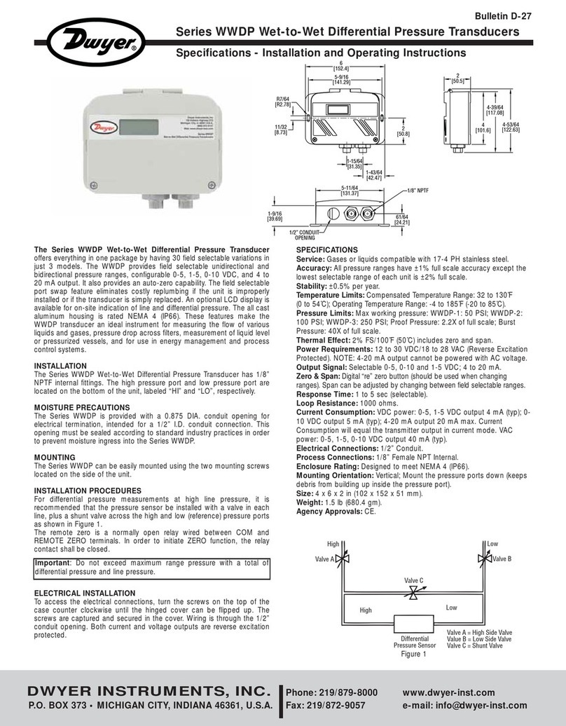
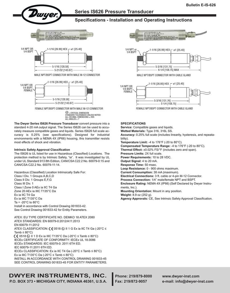
Dwyer Instruments 2200 Series User manual

DWYER INSTRUMENTS, INC.
Phone: 219/879-8000 www.dwyer-inst.com
P.O. Box 373 • Michigan City, IN 46361-0373, U.S.A. Fax: 219/872-9057 e-mail: info@dwyer-inst.com
Series 2200 Current To Pressure Transducer
Specifications - Installation and Operating Instructions
Bulletin E-32
Intrinsically Safe
When used With Approved Barriers
1-15/32
[37.34]
13/16
[20.62] VENT COVER
1/2˝ NPT BOTH
SIDES
1-3/64 [26.56]
4-3/32 [103.9]
1/4˝ FEMALE NPT OUTLET
CONNECTION BOTH SIDES
1-3/4
[44.45]
1/4˝ FEMALE NPT
SUPPLY CONNECTION
3.156
[80.16]
3/8 [9.52] X 5/8 [15.8]
MOUNTING
SLOT 2
PLACES
3-1/2 [88.90]
2-1/2 [63.50]
1/2 [12.70]
4-3/16
[106.38]
Bulletin-E-32 7/15/05 3:03 PM Page 1

INTRODUCTION
The Dwyer Series 2200 Current to Pressure Transducer combines low cost, accuracy, and minimal air consumption with field
proven technology. The design features a rugged, compact housing with FM approved Intrinsically Safe operation when used
with a barrier. This transducer utilizes a virtually weightless membrane that is electro-magnetically positioned over the air flow
consuming minimal air and electrical energy while providing an accurate, precise output pressure signal. This low-mass mem-
brane yields an output that is virtually unaffected by shock, vibration or mounting position. By employing an internal feedback
network, the I/P responds quickly to step input changes, and by balancing air supply and exhaust provides control stability,
while delivering accuracies of ±0.15% or ±0.25%. The pneumatic control signal is enhanced by an integral volume booster. The
unit features easy access to zero and span adjustments along with field selectable direct, reverse and split range operation.
SECTION DESCRIPTION PAGE SECTION DESCRIPTION PAGE
1.0 . . . . . INSTALLATION . . . . . . . . . . . . . . . . . 3 3.0 . . . . . . . . .MAINTENANCE AND REPAIR . . . . . . .8
2.0 . . . . . OPERATION . . . . . . . . . . . . . . . . . . . 6 4.0 . . . . . . . . .TROUBLE SHOOTING GUIDE . . . . . . .9
DANGER, WARNING, CAUTION and NOTE Statements:
• Refers to conditions or hazards which could result in serious personal injury or death.
• Refers to conditions or hazards which could result in personal injury.
• Refers to conditions or hazards which could result in equipment or property damage.
• Alerts you to facts or special instructions.
All DANGER, WARNING, AND CAUTION NOTICES MUST BE COMPLIED WITH IN FULL
SPECIFICATIONS
DANGER
WARNING
CAUTION
NOTE
Input . . . . . . . . . . . . . . . . .
Output . . . . . . . . . . . . . . .
Accuracy . . . . . . . . . . . . .
Repeatability . . . . . . . . . .
Deadband . . . . . . . . . . . .
Stability/Reproducibility .
Position Effect . . . . . . . . .
Vibration Effect . . . . . . . .
Frequency Response . . .
Loop Load . . . . . . . . . . . .
Operating Current . . . . . .
Supply Pressure . . . . . . . .
Supply Pressure Effect . .
Output Capacity . . . . . . .
Air Consumption . . . . . . .
Operating Temperature . .
Temperature Effect . . . . .
RFI-EMI Effect . . . . . . . . .
Operational Modes . . . . .
Failure Mode . . . . . . . . . .
Enclosure . . . . . . . . . . . . .
Electrical Safety . . . . . . . .
Weight . . . . . . . . . . . . . . .
4-20mA
6-30 or 3-15 psig (41-207 or 20-103 kPa)
±0.15% of Span (3-15 psig, 41-207 kPa) & ±0.25% of Span (6-30 psig, 20-103 kPa)
±0.05% of Span
0.02% of Span
0.5% of Span / 6 Months
Not Measurable
<0.25% from 1-200Hz/1g
-3db at 5 Hz (per ISA-S26.4.3.1 Configuration A)
3.8Vdc +5 ohms (195 ohm load at 20mA)
3.7mA min. 200mA max. continuous at 120°F; Half cycle 70 amp 1/120 sec. at 68°F
20 (±2) psig for 3-15 psig output, and 35 (±2) psig for 6-30 psig output.
Not measurable within the recommended supply pressure range
4.0 SCFM (Supply and Exhaust characteristics are balanced to within ±10%)
0.04 SCFM Steady State Average (0.06 SCFM Maximum)
-40° to 150°F (-40° to 66°C)
±0.02% / °F of Span (Range of 0°F to 150°F), or ±0.04% / °F of Span (Range of -40°F to 150°F)
Per SAMA PMC 33.1 standard (b), (c) 20 to 1000MHz, Class 3 effect on zero & span less than 1%. Also
tested and found to comply with BS EN50081-2: 1993 Generic Emissions, Residential, Commercial and
Light Industrial and BS EN50082-2: 1995 Generic Immunity, Residential, Commercial and Light Industrial.
Direct, Reverse, and/or Split-Range (field-selectable, no additional parts needed)
Transducer Always Fails In The Mechanically Direct Mode Regardless Of Mode Selection. Example: Unit
with a 3-15 psi output will fail to 3 psi (or less) with the loss of Input Signal (mA).
Internally purged NEMA 4X. Cast Aluminum with powder coat epoxy
Factory Mutual, CSA and Sira/CENELEC Approved Intrinsically Safe. See Sections 1.5, 1.6 & 1.7.
2.5 lbs (1.13 kg)
Bulletin-E-32 7/15/05 3:03 PM Page 2

MODEL NUMBER
Housing
Blank = *Intrinsically Safe, NEMA 4X
X X X X - X - X
Series Number
22 = 2 Wire I/P
Input
Output
Mounting
1 = 4-20 mA, Factory Mutual Approved Intrinsically Safe
3 = 3-15 PSIG
6 = 6-30 PSIG, (Split Range Not Available On This Model)
- 0 = None
Pipe Mount (Order P.N. A-620 Separately)
Valve Mount (Order P.N. A-621 Separately)
Test Jack for calibration or monitoring of the I/P
transducer. (Order P.N. A-624 Separately)
1. INSTALLATION
1.1. PRE-INSTALLATION REQUIREMENTS
1.1.1 Environment: Suitable for installations in the following locations:
1. 2200 Series I/P
• Intrinsically Safe Operation in Hazardous Locations Outdoors, NEMA 4X.
2. See Section 1.5.0 for Factory Mutual approvals, Section 1.6.0 for Canadian Standards Association approvals and 1.7.0 for
Sira/Cenelec approvals
• All Wiring must be made in accordance with all local and national codes appropriate to the area in which the instrument
is installed. Intrinsically Safe Barriers must be Factory Mutual Research Corporation approved (See Section 1.5.0).
1.1.2 Temperature: Ambient temperature must match specifications
1.1.3 Mounting/Attitude: No Restrictions
1.1.4 Electrical Input: 4-20mAdc current source. It is suggested that shielded wire be used to make electrical connections and
shielding be attached to ground screw and earth ground. (See Figure 1, Page 4).
1.1.5 Air Supply: Clean, dry and oil free instrument air within acceptable pressure range for calibrated output.
1.1.6 A 43 micron external air filter is recommended.
• The air line should be purged of all debris, oil and water.
• Failures attributable to instrument air supply contamination are not covered by the warranty.
• If supply pressure is not within acceptable range, a pressure regulator should be installed (consult factory).
• This instrument vents to atmosphere. The use of supply gas other than air can create a hazardous environment.
1.1.7 Transducer Always Fails In The Mechanically Direct Mode Regardless Of Mode Selection.
1. Example: Unit with a 3-15 psi output will fail to 3 psi (or less) with the loss of the Input Signal (mA).
DANGER
NOTE
CAUTION
Bulletin-E-32 7/15/05 3:03 PM Page 3

1.2. MOUNTING
1.2.1 The 2200 Series housing has been designed for mounting to a standard valve yoke (2.25˝ bolt spacing)
or a 2 1/2˝ (6.4cm) pipe.
1.2.2 Valve Mounting: Two (2) Bolts (5/16˝ x 2˝) and two (2) Lock Washers (5/16˝ nominal) are required.
Order part number A-621 for this option.
1.2.3 Pipe Mount: A Pipe Mount Adapter Accessory is available. Order part number A-620 for this option.
1.2.4 See Dimensional Drawings on Front Cover and illustrations on Back Cover.
1.3. PNEUMATIC CONNECTIONS
1.3.1 One (1) 1/4˝ FNPT port is provided for supply air connections. A filter screen is also supplied with each unit to be
placed in the supply port before the connection is made.
1.3.2 Two (2) 1/4˝ FNPT ports are provided for pneumatic output connections. Either port may be used and one may be
used for the mounting of an output gauge. If no gauge is installed, the unused port must be plugged with the pipe
plug included with the unit.
1.3.3 See Dimensional Drawings on Front and Back Cover.
• Before connecting pneumatics, blow out lines thoroughly.
• Soap test all joints and fittings for leaks.
• Do not use pipe thread tapes on pneumatic piping.
1.4. ELECTRICAL CONNECTIONS
1.4.1 The 2200 Series I/P’s are supplied with two (2) 1/2˝ FNPT electrical conduit connections. The unused connection
requires the insertion of a 1/2˝ FNPT pipe plug.
1.4.2 A two (2) position “Screw-Cage Clamp” terminal block is supplied for 22-12 AWG wire. Wire should be stripped
approximately 1/4˝ before insertion. The Terminals are labeled “+” and “-” on Label.
1.4.3 See Dimensional Drawings on Cover and Figure 1 for references.
• Observe polarity. Reverse polarity will not damage the unit, but unit will not operate.
• Conduit should be connected to prevent condensation from collecting in the instrument.
CAUTION
NOTE
NOTE
CAUTION
Bulletin-E-32 7/15/05 3:03 PM Page 4

2. OPERATION
A block diagram outlining the
operation of the 2200 Series is
shown in Figure 3. A conditioned
4-20mA input signal provides an
electric current to the coil.
This creates a magnetic field
which magnetizes the valve. The
magnetization is proportional to
the input current signal and posi-
tions the membrane/button rela-
tive to the valve seat. The pneu-
matic output (back pressure) is
thereby modulated relative to the
input current. Further condition-
ing of the pneumatic output is
achieved with a volume booster.
Final conditioning of the boosted
pnuematic output signal is
achieved by actually measuring
the output with a pressure sensor.
This signal is then compared with
the input current to achieve the
exact pnuematic output relative to
the 4-20mA current input.
2.1. PROGRAMMING DIRECT, REVERSE OR SPLIT RANGE
2.1.1 Programming is selectable via internal jumpers located on the circuit board. To access, remove the Cover. The label
located on the Module shows the location and position of these jumpers. See Figure 4.
• Disconnect power to unit before removing cover.
2.1.2 To Select desired operating mode, plug in jumpers according to Table 1 on Page 7.
• It is recommended that mode selection be accomplished prior to final inspection.
• When switched from direct to reverse or into split range, the span will remain within ±1%
• TRANSDUCER FAILS IN DIRECT MODE REGARDLESS OF OPERATING MODE SELECTED
CAUTION
NOTE
CAUTION
Bulletin-E-32 7/15/05 3:03 PM Page 5

Direct, Reverse
and Split Range
Inputs & Outputs
The Output of a 2200 Series is
factory set for the desired output.
Table 1 (below) describes the
jumper settings necessary for
Split Range Inputs and Direct or
Reverse Outputs.
NOTE: UNITS WITH OUTPUT RANGES OF 6-30 PSIG
• Units with output ranges of 6-30 psig must be programmed for 1:2 mode to achieve output range.
• Split ranging is not possible on these units, but Reverse mode can be utilized.
• Units factory calibrated for 6-30 psig may have a pneumatic zero too high to recalibrate to 3-15 psig. You can attempt to
recalibrate by changing mode selection from 1:2 to 1:1. If this does not work, the unit must be sent back to the factory for
recalibration.
OUTPUT INPUT SUPPLY DIRECT REVERSE RANGE 1:1 RANGE 1:2 ADJUST
3-15 PSIG 4-20 mA 20 PSIG • • ZERO
3-15 PSIG 4-12 mA 20 PSIG • • ZERO
3-15 PSIG 12-20 mA 20 PSIG • • ZERO
15-3 PSIG 4-20 mA 20 PSIG • • ZERO
15-3 PSIG 4-12 mA 20 PSIG • • ZERO
15-3 PSIG 12-20 mA 20 PSIG • • ZERO
6-30 PSIG 4-20 mA 35 PSIG • • ZERO
30-6 PSIG 4-20 mA 35 PSIG • • ZERO
JUMPER SELECT SWITCH POSITION
Table 1- Jumper Selection for Direct, Reverse & Split Range
Bulletin-E-32 7/15/05 3:03 PM Page 6

2.1.3 PREVENTION OF VALVE OPERATION OVERLAP
There is adequate adjustment of span and zero to put a dead spot in the output to prevent valve operation overlap in split
range. Table 2 shows the values. (If valve overlap is desired, there is also adequate adjustment of span and zero to provide a
margin of overlap).
3. USING THE TEST JACK
The TEST JACK is an optional feature on the 2200 Series I/P. Order part number A-624.
• Do not remove the cover in hazardous areas when the instrument is powered
• Inserting the test jack without connecting a calibrator or ammeter will interrupt the loop power (signal)
3.1. CALIBRATION / OPERATION WITH THE TEST JACK
3.1.6 Removing the Jack Plug will reconnect the unit to the original current source.
3.2. MONITORING WITH THE TEST JACK
3.2.1 Remove the Cover.
3.2.2 Connect the RED wire of the Jack Plug to the
Negative (-) lead of the ammeter.
3.2.3 Connect the BLACK wire of the Jack Plug to the
Positive (+) lead of the ammeter.
3.2.4 Insert the Jack Plug into the TEST JACK.
3.2.5 Use the ammeter to monitor the input current loop
signal.
4. MAINTENANCE AND REPAIR
The 2200 Series I/P has been designed using Dwyer’s solid Module without moving parts on which routine maintenance can
be performed. However, regular routine maintenance is very important and should be performed on both the supply air filtra-
tion and the pneumatic and electrical connections as well.
4.1 EXTERNAL FILTRATION
4.1.1 Failures due to instrument supply air contamination are not covered by original equipment warranty.
4.1.2 Applying heavily oil and/or water laden instrument air will cause premature loading of the unit’s final filter and decay
the supply air pressure thus causing the loss of unit output.
4.1.3 Poor quality instrument air can result in unit failure. It is recommended that a coalescent, oil efficient, 43 micron filter
be placed upstream of each unit where oil and/or water laden instrument air is suspected.
3.1.1 Remove the Cover
3.1.2 Connect the RED wire of the Jack Plug to the
positive (+) lead of the current calibrator
3.1.3 Connect the BLACK and GREEN wires of the
Jack Plug to the Negative (-) lead of the current
calibrator
3.1.4 Insert the Jack Plug into the TEST JACK
3.1.5 The current calibrator is now the input signal
source.
Mode Input(mA) Output(psig) Adjustment
Direct, 1:2
Reverse, 1:2
4-11
13-20
4-11
13-20
3-15
3-15
15-3
15-3
Zero & Span
Zero & Span
Zero & Span
Zero & Span
Table 2 - Valve Operation Overlap
IMPORTANT
DANGER
Bulletin-E-32 7/15/05 3:03 PM Page 7

4.1.4 It is good practice on any instrument air system to provide filtration off the compressor for the removal of oil and water.
We recommend our Part Number F221 or F451 Air Filters. Appropriate filtration is required for proper operation with
minimal maintenance.
4.2 SUPPLY PRESSURE REGULATION
4.2.1 Maintain supply air at pressures required by output range; 20 (±2) psig for the 3-15 psig range and 35 (±2) psig for
the 6-30 psig range. See Table 1, Page 6.
4.2.2 Although the 2200 Series I/P should not be damaged y excessive supply pressure up to the maximum, elevated zero
levels may result. The maximum supply pressure is 10 psig above the maximum calibrated range.
4.3 FACTORY REPAIRS
4.3.1 In the unlikely event the 2200 Series I/P should fail, the unit can be returned to the factory for warranty repair if the
warranty period has not expired.
4.3.2 Repairs for the 2200 Series in or out of warranty are done on a repair/exchange basis.
4.3.3 All units returned for repair are to be shipped freight prepaid, to:
DWYER INSTRUMENTS INCORPORATED
Junction of IN 212 and U.S. 12
Michigan City, Indiana 46360
Attention: REPAIR DEPARTMENT
5. TROUBLESHOOTING GUIDE
PROBLEM
Output Pressure
is 0 PSIG
Output Remains
Between 1-2 PSIG With
Increase Of Input
Unit Will Not Zero
Output pressure below 3 PSI
Output Signal Fails
Below Calibrated
Zero Level, 1-2.5 PSI
Output Signal Fails
To 0 Psig
Unit Will Not Go To
Full Scale With Full
Scale Input
Will Not Split Range
Operates in 1:1 Only
Output Goes To Full
Scale With No Input
LOOK FOR
-Instrument Supply Not Applied . . .
-Module Failure . . . . . . . . . . . . . . . .
-Input Leads Are Reversed . . . . . . .
-Faulty Internal Connections . . . . . .
-Circuit Board Failure . . . . . . . . . . . .
-Oil Contamination in Module . . . . .
-Module Failure . . . . . . . . . . . . . . . .
-Input Current Loop Is Open. . . . . . .
-Loss Of Loop Power . . . . . . . . . . . .
-Open Input Loop Due To . . . . . . . . .
Instr. Protection Circuit Breakdown
-No Power . . . . . . . . . . . . . . . . . . . .
-Module Coil Is Open . . . . . . . . . . . .
-Circuit Board Failure . . . . . . . . . . . .
-Instrument Air Has Failed . . . . . . . .
-External Filter Is Obstructed . . . . .
-Module Is Contaminated . . . . . . . .
-Circuit Board Failure . . . . . . . . . . .
-Leak In Tubing . . . . . . . . . . . . . . . .
-Circuit Board Failure . . . . . . . . . . . .
-Bad Connection . . . . . . . . . . . . . . .
-Circuit Board Failure . . . . . . . . . . . .
-Bad Connection . . . . . . . . . . . . . . .
-Module Is Contaminated . . . . . . . .
SOLUTION
Check Air Supply . . . . . . . . . . . . . . . .
Replace Unit
Reverse Input Leads . . . . . . . . . . . . .
Check Internal Connections. . . . . . . .
Replace Unit
Replace Unit
Replace Filter, Part No. F221 or F451
Check Input Loop
Check Input Loop
Check Input For Overcurrent
Disconnect/Reseat Connectors . . . .
Replace Unit
Replace Unit
Check Supply Air . . . . . . . . . . . . . . . .
Replace Filter . . . . . . . . . . . . . . . . . . .
Replace Unit . . . . . . . . . . . . . . . . . . . .
Replace Unit
Check Tubing . . . . . . . . . . . . . . . . . . .
Replace Unit
Check Connections & Jumpers . . . . .
Replace Unit
Check Connections & Jumpers . . . . .
Replace Unit . . . . . . . . . . . . . . . . . . . .
SEE SECTION
. . . 1.1.5
. . . 1.4
. . . 1.4
. . . 1.4
. . . 1.1.5
. . . 1.1.6
. . . 1.1.6
. . . 1.1.6
. . . 1.3
. . . 2.1
. . . 2.1
. . . 1.1.6
Bulletin-E-32 7/15/05 3:03 PM Page 8

2200 Series I/P with
Pipe Mount, Order
Part Number A-620
2200 Series I/P Valve
Mounted, Order Part
Number A-621
DWYER INSTRUMENTS, INC.
Phone: 219/879-8000 www.dwyer-inst.com
P.O. Box 373 • Michigan City, IN 46361-0373, U.S.A. Fax: 219/872-9057 e-mail: info@dwyer-inst.com
Bulletin-E-32 7/15/05 3:03 PM Page 9
Table of contents
Other Dwyer Instruments Transducer manuals
Popular Transducer manuals by other brands

Fairchild
Fairchild T6100 Installation, operation and maintenance instructions

S+S Regeltechnik
S+S Regeltechnik PREMASGARD 114 Series Operating Instructions, Mounting & Installation

turck
turck IM12-TI02-2TCURTDR-2I Series quick start guide

Petroline-A
Petroline-A TP-140D Operation manual

Airmar
Airmar R99 owner's guide

Airflow
Airflow PT-LE operating instructions