HBM AD104-R2 User manual

Operating instructions
Digital Transducer-
Electronics
AD104-R2,
AD104-R5

Contents Page
Safety notes ..........................................................................................................................................2
1 Intended use................................................................................................................................3
2 Characteristic features ...............................................................................................................3
3 Mechanical construction ............................................................................................................4
4 Electrical construction ...............................................................................................................5
4.1 Function ...............................................................................................................................5
4.2 Signal processing ................................................................................................................6
Electrical connection ...........................................................................................................................8
5.1 Transducer Connection .....................................................................................................10
5.2 Serial Interface RS-232 (only AD104-R2)..........................................................................10
5.3 Serial Interface RS485 (Bus mode with AD104-R5) .........................................................11
6 Command set ............................................................................................................................14
6.1 Command format ...............................................................................................................14
6.2 Answers to commands ......................................................................................................15
6.3 Output types for the measured values...............................................................................15
6.4 Command overview ...........................................................................................................16
7 Individual descriptions of the commands ..............................................................................17
7.1 Interface commands (asynchronous, serial)......................................................................17
7.2 Adjustment and scaling......................................................................................................27
7.3 Measuring ..........................................................................................................................35
7.4 Special functions................................................................................................................47
7.5 Error messages .................................................................................................................62
7.6 Bus termination for RS-485 version...................................................................................63
7.7 Commands for Legal for trade Applications.......................................................................64
7.8 Further commands.............................................................................................................67
7.9 Examples of communication..............................................................................................68
8 Technical data ...........................................................................................................................72

2 / 75
ba_aed104_8_e.doc
Safety notes
•In the normal case the product causes no dangers, provided the notes and instructions for configuring,
installation, operation as intended and maintanance are complied with.
•The safety and accident prevention regulations applicable corresponding to the application must be
observed without fail.
•Installation and commissioning may be performed exclusively by qualified personell.
•Avoid the penetration of dirt and moisture into the interior of the unit when connecting the cables.
•When connecting the cables take measures against electrostatic discharges which can damage the
electronic unit.
•An extra low voltage with safe isolation from the mains is required for the power supply of the unit.
•When connecting additional devices, the safety regulations according to EN610101) must be complied with.
•Shielded cables are required for all connections. The shield must be connected flatly with ground at both
ends.
1) "Safety regulations for electrical measuring, control and laboratory equipment”

AD104-R2, AD104-R5 3 / 75
ba_aed104_8_e.doc
1 Intended use
The digital sensor electronic units AD104 belong to the family of AED components which digitally condition and
network as bus-capable signals of mechanical measured value transducers. The objective of these components
is the digitization and conditioning of the measuring signals directly at the transducer. The AD104 and the
transducer (load cell) form a unit and cannot be replaced separately (transducer calibration of the measurement
chain with SZA/SFA is necessary).
As transducers, calibrated load cells or force transducers ( adjusted in TCZ,TCS, and zero point) can be used.
The measuring amplifier boards AD104 have different interface connections which are produced in the factory
by corresponding assembly:
AD104-Type Interface Interface
Connect.
Bus mode Cable length external
Trigger
AD104-R2 Asynchronous,
serial
RS-232 duplex no < 15m yes
AD104-R5 Asynchronous,
serial
RS-485 -4-wire,
full duplex
yes < 500m yes
The transducer electronic units AD104 are also abbreviated with AED in the following text.
Old type: AD104-R4 Ænew type: is AD104-R5 with external trigger
New type: AD104-R2 with external trigger and RS232 interface.
2 Characteristic features
•Operating voltage 5.6V...15V DC
•4 wire Interface for a full bridge sensor, nominal input range ±2 mV/V, maximal input range ±2.6 mV/V
•Serial interface RS-485 (bus mode) or through RS-232 interface (point - to - point mode)
•Digital filtering, choice of the output speed and scaling of the measured signal
•Separated calibration of transducer and application characteristic
•Storage of the parameters nonvolatile
•All settings are made through the serial interface
•Automatic zero tracking (1d/s, ±2%)
•Automatic intial zero setting (±2%...±20%)
•Trigger functions (level or external trigger)

4 / 75
ba_aed104_8_e.doc
3 Mechanical construction
Fig. 3.1: Example of a mechanical construction of a measuring chain (HBM)
The amplifier circuit board has to be placed in a shielded housing (EMC protection). The cable connections has
to be shielded leads.
With digital transducers (FIT, C16,...) the AD104 is build in the housing of the load cell. For digital measuring
chains the AD104 is included in a separate housing in the cable (degree of protection IP 40).
Warning: The AD104 board is not protected against electrostatic discharges. Appropriate safety
precautions must be taken for handling during assembly into the transducer.
AD104
Load Cell
Shield
Pancon connector
female
1m...500m (depending on the type)
30 cm

AD104-R2, AD104-R5 5 / 75
ba_aed104_8_e.doc
4 Electrical construction
The circuit of the digital transducer electronic unit consists essentially of the following functional groups:
•Transducer supply
•Amplifier
•Analog-digital converter (A/D)
•Microprocessor unit (µP)
•Parameter memory (EEPROM) protected against power failure
•Serial interface (RS232- 2 wire or RS485)
•Power supply
•Trigger input
4.1 Function
Fig. 4.1: Measuring amplifier board AD104 block circuit diagram
The analog transducer signal is initially amplified, filtered and then converted into a digital value in the analog-
digital converter. The digitized measuring signal is processed in the microprocessor. The conditioned signal is
then transmitted to a computer through the serial interface. All parameters can be stored in the EEPROM,
protected against power failures.
Computer
Voltage
stabilizer
Transducer
1200...38400 baud
EEPROM
supply
Identification.,
D igital filter, M eas.
rate, Scaling
Interface setting
Inter-
face
AD
AD 104
µP
< 60mA
5.6...15V
RS-485-
4-wire
RS232
Power
unit
Ext. Trigger

6 / 75
ba_aed104_8_e.doc
The transducer electronic unit is adjusted in the factory to the no-load and the nominal load of the transducer.
The electronic unit determines a factory characteristic through the commands SZA and SFA from these
measured values and images the measured values following later by means of this characteristic.
The following measured values are delivered according to output format (COF):
Output format Input signal Measured values
at
NOV = 0
Measured
values at
NOV > 0
Delivery status
NOV=0
Binary 2 characters
(Integer)
0...Nominal load 0 ... 20 000 Digit 0 ... NOV
Binary 4 characters
(Long Integer)
0...Nominal load 0 ... 5 120 000 Digit 0 ... NOV
ASCII 0...Nominal load 0 ... 1 000 000 Digit 0 ... NOV x
You have the possibility of adapting the characteristic to your requirements (i.e. scale characteristic)
correspondingly with the parameter pair LDW and LWT and to standardize the measured values to the required
scaling value (e.g. 3000d) via the command NOV.
4.2 Signal processing
Measuring
bridge
A
mpli-
fier Filter Factory
scaling
Measur.
rate
User scaling,
Linearization
ZTR, ZSE
Net
ASF ICR
A
DC
Net
measured
value
Gross
measured
value
SZA
SFA
LDW
LWT
NOV
LIC TAV, TAS
TAR
FMD
Fig. 4.2.1: Signal flow diagram
After amplification and AD conversion, the signal is filtered by adjustable digital filters (command ASF). The
factory characteristic is determined with the aid of the commands SZA and SFA.
The measuring signal bandwidth (digital filter) is set with the command ASF. The measuring rate (number of
measurements per time unit) can be changed depending upon the filter bandwidth with the command ICR.
The user can set his own characteristic (commands LDW, LWT, NOV) without changing the factory calibration
(SZA/SFA). Furthermore, gross/net switch-over is available (command TAS). Using the command ZSE an
automatic switch-on zero setting can be activated. An automatic zero tracking function (ZTR) is also available.
For a linearization of the scale characteristic, the command (LIC) is available (with a polynomial of the 3rd
order). The polynomial parameters can be determined by means of a HBM PC program AED_LIC.
The current measured value is retrieved by the command MSV?. The format of the measured value (ASCII or
binary) is set by the command COF. An automatic measured value output can also be selected via the
command COF.
Two types of digital filters, which are switched over using the command FMD, are implemented in the AED. At
FMD0 filters lower than 1 Hz bandwidth are also available. In the filter mode FMD1, filters with fast transient
recovery are activated with high damping in the stop band. You will find detailed information in the chapter
‘Individual descriptions of the commands’.

AD104-R2, AD104-R5 7 / 75
ba_aed104_8_e.doc
The AD104 comprises two trigger functions in order to support functions in packaging machines and
checkweigher:
•triggering by means of an adjustable level (gross and net measured value, for both types)
•external triggering by means of a trigger input
This special measuring mode is activated by means of the command TRC. The measured value determined is
output by means of the command MAV?. For this measuring mode, filter mode FMD1 should be set (fast
settling time).
The measuring speed depends on the preset stop time and the measuring period. The stop time should match
the fast transient recovery of the filter used (ASF).
Level triggering:
This measuring mode is suitable for weighing processes where the scale is relieved in between weighing
events.
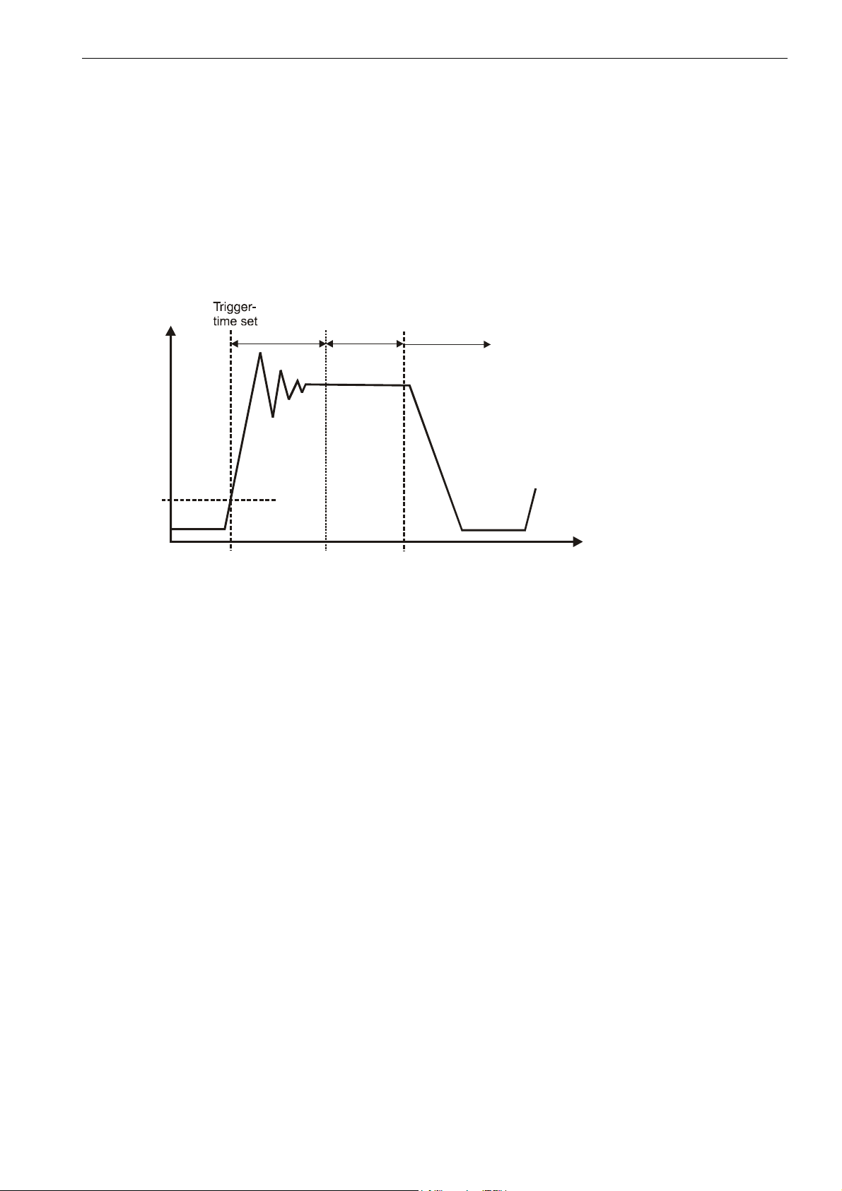
The scale is in a no load condition. The material to be weighed will be placed on the scale, the trigger level is
exceeded, and stop time measurement starts. On expiry of this transient period, the actual weight will be
determined; and on expiry of this measuring period, the actual weight value will be stored in memory. The
weighing process can be restarted only once the weight value is again lower than the trigger level (place scale
in no load condition). In this measurement mode, weight determination does not need to be monitored by an
external computer at high speed. The output memory will contain an invalid value until a new measured value
has been created. After retrieving the contents of the measured value memory by means of the MAV?
command, this memory is reset to an invalid condition (invalid value < - 1600 000).
The periods (stop time and measurement period x 10ms at ICR0) and the trigger level can be freely set by
means of the command TRC. The trigger level will be on the user characteristic (NOV).
External trigger:
Both types support an external trigger instead of the limit value trigger. This trigger has a quiescent signal level
at 0V (=low) and uses the low/high edge to activate the measurement process.
The trigger flank starts the stop time measurement. On expiry of this transient period, the actual weight will be
determined over the measurement period, and the averaged actual weight value will be stored in memory. The
output memory will contain an invalid value until a new measured value has been created. After retrieving the
contents of the measured value memory by means of the MAV? command, this memory is reset to an invalid
condition. The periods (stop time and measurement period x 10ms at ICR0) and the trigger level can be freely
set by means of the command TRC. A renewed trigger flank will restart the measurement process. The scale
does not need to be placed into a no load condition.
During a measuring (waiting time + measuring time) a trigger signal is unvalid (no re-triggering). Within this
mode the parameter trigger level (P3) has no function.
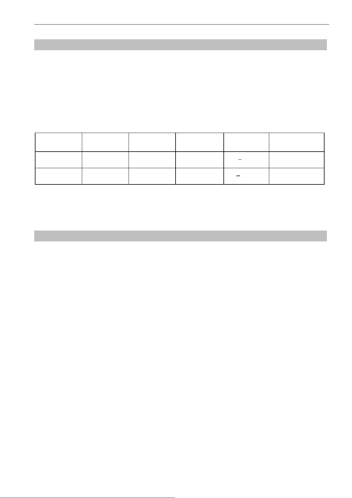
Tr a n s. Re c o v.
time
TRC-command
Parameter 4
Measuring time
TRC-command
Parameter 5
Weig ht
Time
Triggering
(TRC-Command: Parameter 1=1)
Trigger level
TRC-comm.
Parameter 3
if P2=0
Result in output memory

8 / 75
ba_aed104_8_e.doc
5 Electrical connection
Fig. 5: Connection schema of the PCB and shielding concept of a measuring chain
The connection to the PC is effected by means of a 6 / 8 pin Pancon connector. The following pin wirings result
at the connector according to the set interface (i.e. measuring chains of HBM):
AD104 type AD104-R5 AD104-R2
Pancon Connector Signals RS-485 Signals RS-232
1. red UB UB
2. white GND GND
3. blue TA RxD
4. green RA TRG
5. black TB TXD
6. grey RB GND
7. yellow TRG -
8. - -
- do not connect!
The measuring chain of HBM with AD104-R5 has a 8 wire shielded cable.
The measuring chain of HBM with AD104-R2 has a 6 wire shielded cable.
Explanation: UB Supply voltage (+ 5.6V...15V)
GND Ground
RA 4-wire connection AED receiver, line A (=RX-)
RB 4-wire connection AED receiver, line B (=RX+)
TA 4-wire connection AED transmitter, line A (=TX-)
TB 4-wire connection AED transmitter, line B (=TX+)
RxD Receiver data (UART, RS-232)
TxD Transmit data (UART, RS-232)
TRG External trigger signal
(yellow)

AD104-R2, AD104-R5 9 / 75
ba_aed104_8_e.doc
Trigger input (electrical data):
High: 3.2V ... 5V
Low: 0V ... 0.8V
Input current: <2.5 mA
Important notes on EMC protection:
The PCB AD104 alone has no EMC protection. The EMC protection can be achieved in addition with a shielded
housing for the electronic and the use of shielded cable.
Mount the load cell onto a metallic carrier which is connected to the ground connection of the device, or shield
AD104 with the load cell and load introduction parts as a complete unit. The cable shield needs to be connected
with the measuring body of the loadcell and the housing of the AED.
The housing of the AED or the load cell has to be connected via the solder pad to the PCB (see Fig. 5,
‘connection to housing’). The AED unit itself is provided with a protective filter for all interfaces and supply lines.
The connection between load cell and electronics should be as short as possible. Depending on the bridge
resistance of the transducer used, line length, and line cross-section of the transducer connection cable, voltage
drops arise that lead to a reduction in the bridge supply voltage. Additionally, the voltage drop on the connection
cable is also temperature-dependent ( copper resistance ). The transducer output signal also changes in
proportion to the bridge supply voltage.
With the 4-wire circuit used, there still result measurement errors in conditions with changing temperatures,
caused by the temperature-dependent cable resistance and possibly also by transitory resistances in the
connectors.
When setting up a measurement chain (electronics outside the transducer) it should also be noted that the
AD104 uses a rectangular carrier frequency for bridge supply. Therefore, the cable length between AD104 and
the transducer is limited to 100 cm max. For high precision applications(>= 3000d), the length should be
reduced to 30cm (shielded cable, shield connection on the measuring body and on the shielded housing for
AD104).

10 / 75
ba_aed104_8_e.doc
5.1 Transducer Connection
AD104 4
1-Ub
2-GND
3
4
5
6
n.c.
UBr2
IN4
IN1
UBr3
n.c.
Fig. 5.1: Transducer connection with the PCB (n.c. - not connected)
The AED amplifier is allready mounted with the transducer. A changing of the modules (AED or transducer) is
only allowed in HBM factory.
For the transducer connection a 4 core shielded cable has to be used.
Connection Pads for a full bridge:
Pad Discription
UBr2 bridge excitation 2
IN4 amplifier input 4
IN1 amplifier input 1
UBr3 bridge excitation 3
Notes on cable length:
The connection between load cell and electronics should be as short as possible. Depending on the bridge
resistance of the transducer used, line length, and line cross-section of the transducer connection cable, voltage
drops arise that lead to a reduction in the bridge supply voltage. Additionally, the voltage drop on the connection
cable is also temperature-dependent ( copper resistance ). The transducer output signal also changes in
proportion to the bridge supply voltage.
With the 4-wire circuit used, there still result measurement errors in conditions with changing temperatures,
caused by the temperature-dependent cable resistance and possibly also by transitory resistances in the
connectors.
When setting up a measurement chain (electronics outside the transducer) it should also be noted that the
AD104 uses a rectangular carrier frequency for bridge supply. Therefore, the cable length between AD104 and
the transducer is limited to 100 cm max. For high precision applications(>= 3000d), the length should be
reduced to 30cm (shielded cable, shield connection on the measuring body and on the shielded housing for
AD104).
5.2 Serial Interface RS-232 (only AD104-R2)
The AD104-R2 is a version of the AD104 with an asynchronous, serial interface (UART interface with RS-232
line driver). This interface provide a point – to – point communication (no bus mode).
The baud rate of 1200...38400 baud can be selected for this interface. The following specifications result for the
transmission of one character:
Start bit: 1
Number of data bits: 8
Parity bit: none / even
Stop bit: 1

AD104-R2, AD104-R5 11 / 75
ba_aed104_8_e.doc
The connection is made through a six-core cable. The maximum cable length is 15 m. No bus mode is possible
in this type of communications (no bus driver).
AD104 – R2
Y
6 -Ub
Y
5 -GND
Y
12-TRG
Y
10-RxD
Y
8 - n.c.
Y
9 -TxD
Y
7 - n.c.
Fig.5.2: Connections on the PCB (AD104-R2)
The connection scheme for the asynchronous interface results as follows:
AD104-R2 Master
Receiving line RxD TxD transmission line
Transmission line TxD RxD receiver line
Operating voltage UBsupply voltage (5.6V..15VDC)
Ground GND GND Ground
Ext. trigger TRG external trigger signal
The levels on the RxD and TxD lines are RS-232 levels, whereby the quiescent-signal level is <-3V (Low).
External trigger signal:
Quiscent-signal level: TRG= 0V (Low)
Active measuring: TRG= Low-High edge (0V...5V)
If the external trigger is not used, the input remains open.
5.3 Serial Interface RS485 (Bus mode with AD104-R5)
Up to 32 AEDs can be connected to a common bus line through the RS-485 interface. The baud rate can be
selected between 1200 and 38400 baud in this version.
The following specification applies for the transmission of one character:
Start bit: 1
Number of data bits: 8
Parity bit: none / even

12 / 75
ba_aed104_8_e.doc
Stop bit:^ 1
AD104 – R5
Y
6 -Ub
Y
5 -GND
Y
12-TRG
Y
10-TA
Y
8 -RA
Y
9 -TB
Y
7 -RB
Fig. 5.3.1: AD104-R5 for 4-wire bus mode (PCB connections)
1. Long lcable lengths (up to 500m) can be achieved with the aid of the RS485 bus drivers.
2. The bus mode of the AED is designed as master-slave configuration, whereby the AED implements a
slave. Thus all activities of the AED are initiated by the control computer. Each AED receives its own
communication address (00 ... 31) and can be activated through a select command Sii (ii= 00...31). A
broadcast command (S98) is implemented for certain cases of communication. This means that after such
a command, all AED execute the command of the master, but no AED answers. All commands of this
communication as well as corresponding examples are described in Chapter 7.
Figure 5.3.2 shows the connection of the bus to the RS232/RS485 Converter
(HBM Ordering-No. 1-SC232/422A).
Figure 5.3.3 shows the RS485 bus connection.
The terminating resistors of 500 ohms drawn in Figure 5.3.3 for the electrical function of the bus system are
important. These resistors protect the quiescent-signal levels for the receivers on the bus line. The master line
may be terminated with these resistors in this case only at the line ends. The master and the AED with the
address 31 should contain the terminating resistors for the local distribution of the bus connections shown in the
Figure. The AED contains these resistors already. These can be activated by the command STR1 (these
terminating resistors are switched off on factory delivery). These terminations may not be activated more than
twice in one bus.
The HBM interface converter also includes these terminators.
External trigger signal:
Quiscent-signal level: TRG= 0V (Low)
Active measuring: TRG= Low-High edge (0V...5V)
If the external trigger is not used, the input remains open.

AD104-R2, AD104-R5 13 / 75
ba_aed104_8_e.doc
Fig: 5.3.2: Wiring of an AD104-R5 with an interface converter RS232/RS485
RT
TB
RxDTxD on/off
TB
TA
+5V
500Ω
+5V
500Ω
500Ω500Ω
RB
RA
+5V
500Ω
+5V
500Ω
500Ω500Ω
TA RB RA
RT
RxD
TxD on/off
TB TA RB RA
RT
RxD
TxD on/off
TB TA RB RA
Master line 4 - wire
Computer=Master AED = Slave 00 Slave 31. . .
Line
termination
Line
termination
Fig: 5.3.3: Bus structure 4-wire bus (RS485)
The bus wiring is not to be allowed in star configuration. The leads of the slaves are not to be increased of 3m.
The best solution here: choin the main leads directly to the slaves.
The quiescent -signal level on the RS-485 master line results in the 4-wire mode at:
TB - TA > 0.35 V (quiescent -signal level due to the AED terminating resistors)
RB - RA > 0.35 V (quiescent -signal level due to the master terminating resistors)
Since the RS-485 is a differential bus interface, the quiescent-signal levels are also stated as a differential
voltage between the lines (and not related to ground). It must further be noted that this interface tolerates a
maximum common-mode range of +/-7V. If it is necessary, equipotential bonding should be established
between the bus subscribers through a separate line. The cable shield should not be used for this equipotential
bonding.
The shield of the master line is connected with the shield of the AED housing (not with the supply ground).
)
)
)

14 / 75
ba_aed104_8_e.doc
6 Command set
The commands can be classified roughly into:
•Interface commands (ADR, BDR, Sxx, TEX, COF, CSM)
•Commands for adjusting and scaling (SZA, SFA, LDW, LWT, NOV, LIC)
•Commands for the measuring mode (MSV, ASF, ICR, TAR, TAS, TAV, FMD, STP)
•Special commands (ZSE, ZTR, TDD, RES, DPW, SPW, IDN, STR, TRC, MAV)
•Command for legal for trade applications (LFT, TCR, CRC)
6.1 Command format
General notes:
The commands can be input in uppercase or lowercase type.
Each command has to be terminated by a termination character. This can be optionally a line feed (LF) or a
semicolon (;). If only a termination character is sent to the AED, then the input buffer of the AED is cleared.
The statements made in round brackets () in the commands are urgently necessary and must be entered.
Parameters in pointed brackets <> are optional and can also be dispensed with. The brackets themselves are
not entered. Text must be included in “ “.
With numerical entries, leading zeros are suppressed. Numbers can be entered either directly or in exponent
format, e.g. +12000lf or +1,2e4lf. The exponent ecan be one- or two-digit, but a number including sign and
exponent must not be more than 10 characters in length.
Answers consist of ASCII characters and are terminated with CRLF. The binary character output is an
exception (see command MSV).
Each command consists of the command initials, the parameter(s) and the termination character.
Command initials Parameters End character
Input ABC X,Y LF or ;
Output ABC? X,Y LF or ;
Example: MSV?20
20 measured values are output after this command.
All ASCII characters <=- 20H(blank) may stand between command initials, parameters and end character,
except for 11H(ctrl q) and 13H(ctrl s).
H: Hexadecimal.

AD104-R2, AD104-R5 15 / 75
ba_aed104_8_e.doc
6.2 Answers to commands
Answers to inputs (exception COF64...COF79):
Answer End character
Correct input 0 (zero) CRLF
Faulty input ? CRLF
Exceptions: The commands RES, STP, S00 ... S99 deliver no answer.
The command BDR delivers the answer in the new baud rate.
An error flag is received through the command ESR.
Answers to output commands:
Correct command Parameter1, ... Parameter n, or measured values CRLF
Faulty command ? CRLF (error flag via command ESR )
6.3 Output types for the measured values
You can select two types of output and a data delimiter (command TEX).
Output type 1:
The measured values are output arranged beneath one another.
Measured value1 CRLF
Measured value2 CRLF
. . . . . . . .
Measured value n CRLF
Output type 2:
The measured values are output arranged next to one another.
Measured value1 (data delimiter) Measured value2 (data delimiter) ... Measured value n CRLF
The measured value query works with fixed output lengths
(see command COF):
Format command AED answer Number of bytes
COF0; msv?; yyyy CR LF (y- binary) 6
COF2; msv?; yy CR LF (y- binary) 4
COF3; msv?; xxxxxxxx CR LF (x- ASCII) 10
COF9; msv?; xxxxxxxx,xx,xxx CR LF (x- ASCII) 17
There is always a CRLF or the data delimiter defined by the command TEX as end identification of the
measured value output. However these characters must not be filtered out as end identification in the binary
output, since these characters can also be contained in the binary code of the measured value. Therefore only
counting the bytes helps in the binary output. The corresponding places after CR or LF or the data delimiter can
then be enquired for subsequent syntax testing.
Password protection:
The password protection of the AED comprises important settings for the characteristic of the scale
and its identification. Commands with password protection are activated only after the password is
entered. These commands are answered with “?“ without entry of the password through the command
SPW.

16 / 75
ba_aed104_8_e.doc
6.4 Command overview
Command PW TDD 1 Function Page
ADR xAdress18
ASF x Digital filter 40
BDR x Baud rate 19
COF x Output format in MSV? 20
CRC external checksum for legal for trade applic. 66
CSM x checksum in MSV status 24
DPW Define password 47
ENU Dimensional unit 50
ESR Status 62
FMD x Filter mode 42
ICR x Measuring rate 43
IDN Identification of transducer type and serial number 51
LDW x Zero point, user characteristic 32
LFT x Legal for trade applications 64
LIC x Linearization 57
LWT x Nominal value, user characteristic 33
MAV Measured value, trigger function 58
MSV Measured value output 36
NOV x x Nominal value scaling 34
RES Reset 49
S... Select of AED in bus operation 26
SFA x Internal nominal value, factory characteristic 30
SPW Password entry 48
STP Messwertausgabe stoppen 39
STR x Switch bus termination resistors on/off 63
SZA x Stop measured value output 29
TAR Tare mode 44
TAS x Gross/net switch-over 46
TAV x Tare value 45
TDD1/2 Store setting in EEPROM, read EEPROM 52
TDD0 x Factory setting 52
TEX x Data delimiter for measured value output 25
TCR Trade counter 65
TRC x Trigger setting 59
ZSE x Initial zero setting 55
ZTR x Automatic zero tracking 56
TDD1 – stored with TDD1 command
PW – protected by password with commands DPW/SPW
The following commands result in no change to the AED setting:
ACL, ASS, CAL, COR, GRU (compatibility with other AED versions).

AD104-R2, AD104-R5 17 / 75
ba_aed104_8_e.doc
7 Individual descriptions of the commands
7.1 Interface commands (asynchronous, serial)
Characteristic data of the interfaces
Start bit: 1
Word length: 8 bits
Parity: none / even
Stop bit: 1
Software handshake (XON / XOFF) is possible
Baud rate: 1200; 2400; 4800; 9600;19200; 38400 baud
The asynchronous interface of the AED is a serial interface, i.e. the data are transmitted bit for bit after one
another and asynchronously. Asynchronous means that the transmission works without a clock signal.
A start bit is set before each data byte. The bits of the word, a parity bit for the transmission protocol (optional)
and a stop bit then follow.
Fig. 7.1.1: Composition of a character
Since the data are transmitted after one another, the transmission speed must agree with the reception speed.
The number of bits per second is called baud rate.
The exact baud rate of the receiver is synchronized with the start bit for each transmitted character. The data
bits which all have the same length then follow. After the stop bit is reached, the receiver goes into a ‘waiting
position’ until it is reactivated by the next start bit.
The number of characters per measured value depends upon the selected output format (COF command) and
can be 2 to 17 characters (see also COF command).
The interface must be configured to build up the communication between AED and computer. The following
commands are provided in the AED for this : ADR; BDR; COF; TEX; S..;
Start Parity Stop
1 Bit Word length = 8 data bits 1 Bit 1 Bit
1 character

18 / 75
ba_aed104_8_e.doc
ADR Address
(device address)
Range: 0...31
Factory setting: 31
Response time: <15ms
Parameters: 2
Password protection: none
Parameter protect.: with command TDD1
Input: ADR(new address),<"Serial No.">;
Entry of the device address as decimal number 0...31.
The serial number can also be stated optionally as 2nd parameter. The new address is then entered only for the
AED with the stated serial number. This makes it possible to change device addresses in the case of several
AEDs with the same address (initialization of the bus mode).
The serial number must be stated in “ “ as in the command IDN.
Example: ADR25,"007" CRLF
Query: ADR?; 25CRLF (Example)
Effect: Output of the device address as decimal number 0...31

AD104-R2, AD104-R5 19 / 75
ba_aed104_8_e.doc
BDR Baud Rate
(Baud rate)
Baud rates: 1200, 2400, 4800, 9600, 19200, 38400 Baud
Factory setting: 9600 Baud and even parity
Response time: <15ms
Parameters: 1
Password protection: none
Parameter protect.: with command TDD1
Input: BDR <Baudrate>,<Parity>
Entry of the required baud rate as decimal number.
Possible baud rates are:
1200, 2400, 4800, 9600, 19200, 38400 Baud
Input or the requested parity:
0= without parity bit
1= with even parity bit
Important Note
The answer is given in the new setting (baud rate, parity). Communication is no longer possible initially after a
changed baud rate. The computer must also be changed over to the newly selected baud rate setting.So that
the baud rate remains changed permanently, it must be stored in the EEPROM with the command TDD1. This
procedure serves also as safeguard that no baud rates can be set in the AED which the remote station does not
support. If the newly entered baud rate is not stored, the AED reports after a reset or power On again in the
previously valid baud rate.
Query: BDR?;
Effect: Output of the set baud rate, Identification for parity bit
Example: BDR?; 9600,1 CRLF corresponds to 9600 baud, even parity
This manual suits for next models
1
Table of contents
Other HBM Transducer manuals
Popular Transducer manuals by other brands

controlair
controlair 550 Series Installation, operation and maintenance instructions

Rockford Fosgate
Rockford Fosgate IBeam IB-200 Installation & operation

M-system
M-system LECA instruction manual

Fisher
Fisher 646 instruction manual

Simex
Simex TRS-02a user manual

Sensor Technology
Sensor Technology TorqSense RWT410 Series user manual