HBM U5 Series User manual

Force transducer
U5
Mounting Instructions
B 20.U5.10 en
SUNSTAR传感与控制 http://www.sensor-ic.com/ TEL:0755-83376549 FAX:0755-83376182 E-MAIL:[email protected]
SUNSTAR自动化 http://www.sensor-ic.com/ TEL: 0755-83376489 FAX:0755-83376182 E-MAIL:[email protected]

SUNSTAR传感与控制 http://www.sensor-ic.com/ TEL:0755-83376549 FAX:0755-83376182 E-MAIL:[email protected]
SUNSTAR自动化 http://www.sensor-ic.com/ TEL: 0755-83376489 FAX:0755-83376182 E-MAIL:[email protected]

3
U5
HBM 29.6.00
Contents Page
Safety instructions 4. . . . . . . . . . . . . . . . . . . . . . . . . . . . . . . . . . . . . . . . . . . . . .
1 Scope of supply 7. . . . . . . . . . . . . . . . . . . . . . . . . . . . . . . . . . . . . . . . . . . . .
2 Applicationinformation 8. . . . . . . . . . . . . . . . . . . . . . . . . . . . . . . . . . . . . .
3 Structure and mode of operation 9. . . . . . . . . . . . . . . . . . . . . . . . . . . . . .
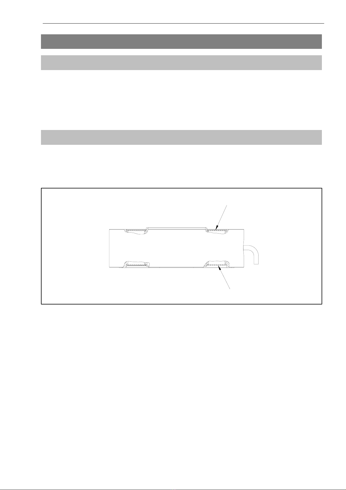
3.1 Measuring element 9. . . . . . . . . . . . . . . . . . . . . . . . . . . . . . . . . . . . . . . .
3.2 Housing 9. . . . . . . . . . . . . . . . . . . . . . . . . . . . . . . . . . . . . . . . . . . . . . . . . .
4 Conditionson site 10. . . . . . . . . . . . . . . . . . . . . . . . . . . . . . . . . . . . . . . . . . .
4.1 Ambient temperature 10. . . . . . . . . . . . . . . . . . . . . . . . . . . . . . . . . . . . . . .
4.2 Moisture 10. . . . . . . . . . . . . . . . . . . . . . . . . . . . . . . . . . . . . . . . . . . . . . . . .
4.3 Deposits 10. . . . . . . . . . . . . . . . . . . . . . . . . . . . . . . . . . . . . . . . . . . . . . . . .
5 Mechanicalinstallation 11. . . . . . . . . . . . . . . . . . . . . . . . . . . . . . . . . . . . . . .
5.1 Important measures for installation 11. . . . . . . . . . . . . . . . . . . . . . . . . . .
5.2 General installation guidelines 12. . . . . . . . . . . . . . . . . . . . . . . . . . . . . . .
5.3 Installation for tensile loading/compressive loading 13. . . . . . . . . . . . .
5.3.1 Installation without adapter 13. . . . . . . . . . . . . . . . . . . . . . . . . . .
5.3.2 Installation with tensile force adapter and knuckle eye 14. . . .
5.3.3 Installation with two knuckle eyes 15. . . . . . . . . . . . . . . . . . . . . .
5.3.4 Installation with compressive force adapter 17. . . . . . . . . . . . .
6 Electrical connection 18. . . . . . . . . . . . . . . . . . . . . . . . . . . . . . . . . . . . . . . . .
6.1 Order code 20. . . . . . . . . . . . . . . . . . . . . . . . . . . . . . . . . . . . . . . . . . . . . . .
6.2 Instructions for cabling 21. . . . . . . . . . . . . . . . . . . . . . . . . . . . . . . . . . . . .
7 Specifications(VDI/VDE2638) 22. . . . . . . . . . . . . . . . . . . . . . . . . . . . . . . . .
8 Dimensions Standard Version 24. . . . . . . . . . . . . . . . . . . . . . . . . . . . . . . . .
8.1 Dimensions mounting accessories for measurement
of compressive/tensile torce 25. . . . . . . . . . . . . . . . . . . . . . . . . . . . . . . .
8.2 Knuckle eyes/thrust piece 26. . . . . . . . . . . . . . . . . . . . . . . . . . . . . . . . . .
9 Declaration of conformity 28. . . . . . . . . . . . . . . . . . . . . . . . . . . . . . . . . . . . .
SUNSTAR传感与控制 http://www.sensor-ic.com/ TEL:0755-83376549 FAX:0755-83376182 E-MAIL:[email protected]
SUNSTAR自动化 http://www.sensor-ic.com/ TEL: 0755-83376489 FAX:0755-83376182 E-MAIL:[email protected]

4U5
HBM 29.6.00
Safety instructions
Use in accordance with the regulations
Force transducers in the U5 range are designed for force measurements on
test benches/in press-fit devices/test devices/pressing. Use for any additional
purpose shall be deemed to be not in accordance with the regulations.
In the interests of safety, the transducer should only be operated as described
in the Mounting Instructions. It is also essential to observe the appropriate
legal and safety regulations for the application concerned during use. The
same applies to the use of accessories.
The transducer is not a safety element within the meaning of its use as
intended. Proper and safe operation of this transducer requires proper
transportation, correct storage, assembly and mounting and careful operation
and maintenance.
General dangers of failing to follow the safety instructions
The U5 force transducer corresponds to the state of the art and is fail-safe.
The transducers can give rise to remaining dangers if they are inappropriately
installed and operated by untrained personnel.
Everyone involved with the installation, commissioning, maintenance or repair
of a force transducer must have read and understood the Mounting
Instructions and in particular the technical safety instructions.
Remaining dangers
The scope of supply and performance of the transducer covers only a small
area of force measurement technique. In addition, equipment planners,
installers and operators should plan, implement and respond to the safety
engineering considerations of force measurement technique in such a way as
to minimise remaining dangers. Prevailing regulations must be complied with
at all times. There must be reference to the remaining dangers connected with
force measurement technique.
SUNSTAR传感与控制 http://www.sensor-ic.com/ TEL:0755-83376549 FAX:0755-83376182 E-MAIL:[email protected]
SUNSTAR自动化 http://www.sensor-ic.com/ TEL: 0755-83376489 FAX:0755-83376182 E-MAIL:[email protected]

5
U5
HBM 29.6.00
In these mounting instructions remaining dangers are pointed out using the
following symbols:
Symbol: WARNING
Meaning:
Dangerous situation
Warns of a potentially dangerous situation in which failure to comply with
safety requirements can result in death or serious physical injury.
Symbol: CAUTION
Meaning:
Possibly dangerous situation
Warns of a potentially dangerous situation in which failure to comply with
safety requirements could lead to damage to property, slight or moderate
physical injury.
Symbol: NOTE
Means that important information about the product or its handling is being
given.
Symbol:
Meaning:
CE mark
The CE mark signals a guarantee by the manufacturer that his product meets
the requirements of the relevant EC directives (see Declaration of conformity
at the end of this Operating Manual).
SUNSTAR传感与控制 http://www.sensor-ic.com/ TEL:0755-83376549 FAX:0755-83376182 E-MAIL:[email protected]
SUNSTAR自动化 http://www.sensor-ic.com/ TEL: 0755-83376489 FAX:0755-83376182 E-MAIL:[email protected]

6U5
HBM 29.6.00
Conversions and modifications
The transducer must not be modified from the design or safety engineering
point of view except with our express agreement. Any modification shall
exclude all liability on our part for any damage resulting therefrom. Mounting
and dismounting the adapter in accordance with Chapter 5 excluded.
Qualified personnel
This instrument is only to be installed by qualified personnel strictly in
accordance with the technical data and with the safety rules and regulations
which follow. It is also essential to observe the appropriate legal and safety
regulations for the application concerned. The same applies to the use of
accessories.
Qualified personnel means persons entrusted with the installation, fitting,
commissioning and operation of the product who possess the appropriate
qualifications for their function.
Conditions on site
Protect the transducer from damp and weather influences such as rain, snow,
etc.
Maintenance
The U5 force transducer is maintenance free.
Accident prevention
Although the specified nominal force in the destructive range is several times
the full scale value, the relevant accident prevention regulations from the
trade associations must be taken into consideration.
SUNSTAR传感与控制 http://www.sensor-ic.com/ TEL:0755-83376549 FAX:0755-83376182 E-MAIL:[email protected]
SUNSTAR自动化 http://www.sensor-ic.com/ TEL: 0755-83376489 FAX:0755-83376182 E-MAIL:[email protected]

7
U5
HBM 29.6.00
1 Scope of supply
•1 Force transducer U5
•1 Operating Manual U5
Accessories (not included in the scope of supply):
•Adapter
Measuring range 100kN:
Compressive force adapter each with 8 screws M12 x 50
Order no. 2–9278.0349
Tensile force adapter each with 8 screws M12 x 50
Order no. 2–9278.0350
Bearing plate each with 8 screws M12 x 30
Order no. 2–9278.0351
Measuring range 200kN:
Compressive force adapter each with 8 screws M16 x 55
Order no. 2–9278.0352
Tensile force adapter each with 8 screws M16 x 55
Order no. 2–9278.0353
Bearing plate each with 8 screws M16 x 40
Order no. 2–9278.0354
Measuring range 500kN:
Compressive force adapter each with 8 screws M20 x 65
Order no. 2–9278.0355
Tensile force adapter each with 8 screws M20 x 65
Order no. 2–9278.0356
Bearing plate each with 8 screws M20 x 65
Order no. 2–9278.0357
•Knuckle eye ZGUW
100 kN: Order no. 1–Z4/100kN/ZGUW
200 kN: Order no. 1–U2A/10t/ZGUW
500 kN: Order no. 1–Z4/500kN/ZGUW
•Thrust piece EPO (including strain washer)
100 kN: Order no. 1–EPO3R/20T
200 kN: Order no. 1–EPO3R/20T
500 kN: Order no. 1–EPO3/100T
SUNSTAR传感与控制 http://www.sensor-ic.com/ TEL:0755-83376549 FAX:0755-83376182 E-MAIL:[email protected]
SUNSTAR自动化 http://www.sensor-ic.com/ TEL: 0755-83376489 FAX:0755-83376182 E-MAIL:[email protected]

8U5
HBM 29.6.00
•Cable/Connector
Connection cable Kab139A–6, 6m, with cable socket 723 and free ends;
Order number: 1–KAB139A–6
Connector MS3106PEMV mounted on Kab139A;
Order number: D–MS/MONT
15–pin D–Sub connector (male) mounted on Kab139A;
Order no.: D–15D/MONT
2 Application information
Force transducers of the U5 type series are suitable for measuring tensile and
compressive forces. They measure static and dynamic forces extremely
accurately and therefore require careful handling. You must take particular
care when transporting and installing the devices. If you knock or drop the
transducers, this could permanently damage them.
The housing provides an elaborate seal to protect the sensitive strain gauge
applications and it is essential that this is preserved. Therefore be particularly
careful around the top and bottom of the housing (see Fig. 3.1).
The limits for the permissible mechanical thermal and electrical stresses are
stated in the Specifications. It is essential that these are taken into
consideration in planning the measuring set-up, during installation and finally,
during operation.
SUNSTAR传感与控制 http://www.sensor-ic.com/ TEL:0755-83376549 FAX:0755-83376182 E-MAIL:[email protected]
SUNSTAR自动化 http://www.sensor-ic.com/ TEL: 0755-83376489 FAX:0755-83376182 E-MAIL:[email protected]

9
U5
HBM 29.6.00
3 Structure and mode of operation
3.1 Measuring element
The measuring element is a measuring spring made from stainless steel, to
which strain gauges (S.G.) are applied. The S.G. are arranged so that four of
them can be strained and the other four compressed when the transducer
reacts to a force.
3.2 Housing
The housing with the integrated measuring spring is completed underneath
and on top by an attached cover. No weight must be placed on this cover. It
should be protected against mechanical damage.
Cover
Cover
Fig. 3.1 Cover position
SUNSTAR传感与控制 http://www.sensor-ic.com/ TEL:0755-83376549 FAX:0755-83376182 E-MAIL:[email protected]
SUNSTAR自动化 http://www.sensor-ic.com/ TEL: 0755-83376489 FAX:0755-83376182 E-MAIL:[email protected]

10 U5
HBM 29.6.00
4 Conditions on site
4.1 Ambient temperature
The effects of temperature on the zero signal and on the sensitivity are
compensated. To achieve optimal measurement results the nominal
temperature range must be maintained. Temperature-induced measurement
errors are caused by heating (e.g. radiant heat) or cooling on one side. A
radiation barrier and all-round thermal insulation will produce a marked
improvement, but should not form a force shunt radiation shield
4.2 Moisture
Extreme humidity or a tropical climate should be avoided if this means that the
classified limit values are exceeded (degree of protection IP65 under DIN
EN 60529).
NOTE
Moisture must not be allowed to penetrate the free end of the
connection cable.
4.3 Deposits
Dust, dirt and other foreign bodies must not be allowed to accumulate such
that they divert part of the measured force onto the housing and so falsify the
measured value (force shunt).
NOTE
Foreign bodies must not be allowed to clog the gap beneath the
flange surface.
SUNSTAR传感与控制 http://www.sensor-ic.com/ TEL:0755-83376549 FAX:0755-83376182 E-MAIL:[email protected]
SUNSTAR自动化 http://www.sensor-ic.com/ TEL: 0755-83376489 FAX:0755-83376182 E-MAIL:[email protected]

11
U5
HBM 29.6.00
5 Mechanical installation
5.1 Important measures for installation
•Treat the transducer gently.
•Make sure that there is a rigid base when measuring compressive forces.
•The force-introduction surfaces must be totally clean and fully bearing.
•Comply with the engagement depths for threaded rods or knuckle eyes.
•Do not overload the transducer.
•Either during installation or immediately afterwards, the transducer should
be bridged by a 50mm2stranded copper wire (highly flexible earthing cable
EEK from the HBM line). The cable is attached by screws both above and
below the transducer. This prevents welding current flowing over the
transducer and welding the force introduction point.
WARNING
If there is a risk of breakage through overload on the transducer
and thus a risk to persons, additional safety measures are to be
taken.
SUNSTAR传感与控制 http://www.sensor-ic.com/ TEL:0755-83376549 FAX:0755-83376182 E-MAIL:[email protected]
SUNSTAR自动化 http://www.sensor-ic.com/ TEL: 0755-83376489 FAX:0755-83376182 E-MAIL:[email protected]

12 U5
HBM 29.6.00
5.2 General installation guidelines
The direction of measurement in which the forces work should be as much
towards the transducer as possible. Torsion and bending moments, eccentric
loading and transverse forces may result in measurement errors and if the
limit values are exceeded, could destroy the transducer.
The transducer can take up 50% (60% at 100kN) of its nominal force as
transverse force by reference to a force introduction point on the
force-introduction surface, without losing its mechanical competence.
As mounting accessories for the transducers, HBM supplies U5 standard
range knuckle eyes and adapters as accessories. Knuckle eyes are suitable
for use during quasi-static loading (10Hz alternating loads). In the case of
dynamic loading at a higher frequency, you should use flexible tension bars.
Knuckle eyes prevent the introduction of torsional moments and when 2
knuckle eyes are used, stop bending moments and transverse and angular
loading being introduced in the transducers.
Various installation fastenings are possible for the transducer (see Fig. 5.1 to
Fig. 5.4).
The sensitivity of the transducer is adjusted for installation using the flange
thread. Should the characteristic tolerance for using the through-holes be
insufficient, it is possible to carry out a factory calibration for this special
installation situation.
SUNSTAR传感与控制 http://www.sensor-ic.com/ TEL:0755-83376549 FAX:0755-83376182 E-MAIL:[email protected]
SUNSTAR自动化 http://www.sensor-ic.com/ TEL: 0755-83376489 FAX:0755-83376182 E-MAIL:[email protected]

13
U5
HBM 29.6.00
5.3 Installation for tensile loading/compressive loading
5.3.1 Installation without adapter
The transducer is screwed directly on to an existing structural element (e.g.
profile, cover, plate). This type of installation enables the transducers to
measure axial forces in the tensile force and compressive force directions.
Alternating loads can also be recorded perfectly. To achieve this, the
transducer must be mounted without any axial play, which is made easier by
centering aids on the top and bottom of the transducers.
Usable centering assistance on the top is 2.5mm and on the bottom, 1.5mm
(see page 24).
+The structural elements provided by the customer must be parallel to one
another. The screws must be tightened in a diagonally opposite sequence.
Section drawn rotated at the plane of projec-
tion
Installation with flange through-hole Installation with flange thread
provided by
customer
provided by
customer
M2(MA)
M1(MA)
U5
M3(MA)
M2(MA)
Fig. 5.1 Installation for tensile loading/compressive loading
Nominal
force (kN) Starting tor-
que MA(Nm) Screws for transducer mounting M1(flange
through-hole)
Resistance class 10.9
metric UNF
T
(mm)
100 115 8 x M12 8x1/2” approx. 15
200 280 8 x M16 8x5/8” approx. 19
500 560 8 x M20 8x3/4” approx. 23
Nominal
force (kN) Screws for transducer mounting M3(flange
thread) Resistance class 10.9 Screws M2
Resistance class 10.9
100 8xM12 8 x M12
200 8xM16 8 x M16
500 8xM20 8 x M20
SUNSTAR传感与控制 http://www.sensor-ic.com/ TEL:0755-83376549 FAX:0755-83376182 E-MAIL:[email protected]
SUNSTAR自动化 http://www.sensor-ic.com/ TEL: 0755-83376489 FAX:0755-83376182 E-MAIL:[email protected]

14 U5
HBM 29.6.00
5.3.2 Installation with tensile force adapter and knuckle eye
If the transducer is to be tensile force loaded, it can be mounted with an
adapter (HBM accessory) and a knuckle eye. A centering hole is located on
both sides of the transducer.
When knuckle eyes are used, the breaking force is reduced to 150%. Knuckle
eyes are only suitable for use with quasi-static loading (alternating loads
F10Hz).
Installation with flange through-hole Installation with flange thread
provided by
customer
provided by
customer
Tensile force
adapter Tensile force
adapter
Section
drawn rota-
ted at the
plane of pro-
jection
lock nut (MB)
Knuckle eye
ZGUW
lock nut (MB)
Knuckle eye
ZGUW
M2(MA)M1(MA)M
2
(MA)M3(MA)
Hmin
T
Fig. 5.2 Installation for tensile loading
Nominal
force (kN) HMin (mm) Starting torque
MA(Nm) Starting torque
MB(Nm) Screws for adapter
mounting M21) T (mm)
100 app.159 115 1900 8xM12x50 app. 15
200 app. 203 280 4300 8xM16x55 app. 19
500 app. 319 560 –2) 8xM20x70 app. 23
1) included in the scope of supply for the tensile force adapter
2) secured with 2 screws to prevent torsion
Nominal
force
(kN)
Screws for transducer mounting M1
(flange through-hole)
Resistance class 10.9
metric UNF
Screws for transducer mounting M3
(flange thread) Resistance class 10.9
100 8 x M12 8x1/2” 8xM12
200 8 x M16 8x5/8” 8xM16
500 8 x M20 8x3/4” 8xM20
SUNSTAR传感与控制 http://www.sensor-ic.com/ TEL:0755-83376549 FAX:0755-83376182 E-MAIL:[email protected]
SUNSTAR自动化 http://www.sensor-ic.com/ TEL: 0755-83376489 FAX:0755-83376182 E-MAIL:[email protected]

15
U5
HBM 29.6.00
Attaching the knuckle eye:
•Screw the correct adapter (dependent on nominal force!; see Chapter1) to
U5 (taking screw length into account)
•Turn the lock nut back as far as the eye
•Screw the knuckle eye into the adapter as far as the stop
•Unscrew knuckle eye 1 to 2 turns and align
•Load eye with nominal load
•Tighten lock nut (MB, lock using the flat of the adapter)
CAUTION
When locking with the lock nut, under no circumstances let the
torque be transmitted through the transducer.
5.3.3 Installation with two knuckle eyes
tensile force
adapter
M2(MA)
M1(MA)
knuckle eye
ZGUW
lock nut (MB)
lock nut (MB)
bearing plate
Hmin
Fig. 5.3 Installation for tensile loading with two knuckle eyes
SUNSTAR传感与控制 http://www.sensor-ic.com/ TEL:0755-83376549 FAX:0755-83376182 E-MAIL:[email protected]
SUNSTAR自动化 http://www.sensor-ic.com/ TEL: 0755-83376489 FAX:0755-83376182 E-MAIL:[email protected]

16 U5
HBM 29.6.00
When knuckle eyes are used, the breaking force is reduced to 150%. Knuckle
eyes are only suitable for use with quasi-static loading (alternating loads
F10Hz).
Nominal
force (kN) HMin
(mm) Starting torque
MA(Nm) Starting
torque MB
(Nm)
Screws for
adapter
mounting M2
Screws for adapter
mounting M1
metric
100 app.269 115 1900 8xM12x50 8xM12
200 app.351 280 4300 8xM16x55 8xM16
500 app.494 560 – *)8xM20x65 8xM20
*) secured with 2 screws to prevent torsion
Attaching the knuckle eye:
•Screw the correct adapter (dependent on nominal force!, see Chapter1) to
U5 (taking screw length into account)
•Turn the lock nut back as far as the eye
•Screw the knuckle eye into the adapter as far as the stop
•Unscrew knuckle eye 1 to 2 turns and align
•Load eye with nominal load
•Tighten the lock nut (MB)
CAUTION
When locking with the lock nut, under no circumstances let the
torque be transmitted through the transducer.
SUNSTAR传感与控制 http://www.sensor-ic.com/ TEL:0755-83376549 FAX:0755-83376182 E-MAIL:[email protected]
SUNSTAR自动化 http://www.sensor-ic.com/ TEL: 0755-83376489 FAX:0755-83376182 E-MAIL:[email protected]

17
U5
HBM 29.6.00
5.3.4 Installation with compressive force adapter
Section drawn rotated at the plane of projection
Installation with flange through-hole Installation with flange tapped hole
Thrust piece and strain washer:
100kN and 200kN
compressive
force adapter
A
Section A Thrust piece and strain washer: 500kN
120
70
Ø18
(M16)
Ø13
(M12)
10
20
10
thrust piece EPO (strain washer not shown)
A
M3(MA)M2(MA)
M1(MA)compressive
force adapter
provided by
customer
147
Ø
Ø
Ø110
T
H
Fig. 5.4 Installation for compressive loading with the compressive force adapter
Nominal force
(kN) HMin
(mm) Starting torque MA
(Nm) Screws for adapter
mounting M2T (mm)
100 99 115 M12x50 approx.15
200 115 280 M16x55 approx.19
500 157 560 M20x65 approx.23
Nominal
force (kN) Screws for transducer mounting M1(flange
through-hole)
Resistance class 10.9
metric UNF
Screws for transducer
mounting M3(flange
thread) Resistance class
10.9
100 8xM12 8x1/2” 8xM12
200 8xM16 8x5/8” 8xM16
500 8xM20 8x3/4” 8xM20
SUNSTAR传感与控制 http://www.sensor-ic.com/ TEL:0755-83376549 FAX:0755-83376182 E-MAIL:[email protected]
SUNSTAR自动化 http://www.sensor-ic.com/ TEL: 0755-83376489 FAX:0755-83376182 E-MAIL:[email protected]

18 U5
HBM 29.6.00
6 Electrical connection
Transducers are available with the following electrical connections:
•Cable with free ends (standard)
Cable sheath cut at the circumfe-
rence
Order code: K or Y
10 100
10
WH (white)
BK (black)
RD (red)
BU (blue)
GN (green)
GY (grey)
Shield
Measurement signal (+) UA
Excitation voltage (+) UB
Sensor circuit (–)
Sensor circuit (+)
Excitation voltage (–) UB
Measurement signal (–) UA
Cable shielding, connected to housing
Six-wire connection
Fig. 6.1: Pin assignment of the U5 with free ends
SUNSTAR传感与控制 http://www.sensor-ic.com/ TEL:0755-83376549 FAX:0755-83376182 E-MAIL:[email protected]
SUNSTAR自动化 http://www.sensor-ic.com/ TEL: 0755-83376489 FAX:0755-83376182 E-MAIL:[email protected]

19
U5
HBM 29.6.00
•There is a 7-pin male device connector (Binder 723) on the housing
Order code: P
Binder pin
male connec-
tor
Assignment Wire
colour
1Measurement signal (+) WH
2Excitation voltage (–) BK
3Excitation voltage (+) BU
4Measurement signal (–) RD
5No function –
6Sensor circuit (+) GN
7Sensor circuit (–) GY
Fig. 6.2: Binder connector series 723 (attached)
•Cable with MS connector (male)
Order code: M or N
MS male con-
nector pin Assignment Wire
colour
AMeasurement signal (+) WH
BExcitation voltage (–) BK
CExcitation voltage (+) BU
DMeasurement signal (–) RD
ENo function –
FSensor circuit (+) GN
GSensor circuit (–) GY
Fig. 6.3: MS male connector pin assignment
61
572
43
Binder 723
Top view
FA
EGB
DC
Top view
SUNSTAR传感与控制 http://www.sensor-ic.com/ TEL:0755-83376549 FAX:0755-83376182 E-MAIL:[email protected]
SUNSTAR自动化 http://www.sensor-ic.com/ TEL: 0755-83376489 FAX:0755-83376182 E-MAIL:[email protected]

20 U5
HBM 29.6.00
•Cable with sub-D male connector
Order code: D or F
Sub-D con-
nector pin Assignment Wire
colour
1Measurement signal (+) WH
2Excitation voltage (–) BK
3Excitation voltage (+) BU
4Measurement signal (–) RD
13 Sensor circuit (+) GN
12 Sensor circuit (–) GY
Fig. 6.4: Sub-D male connector assignment
The cable shielding is connected in accordance with the Greenline concept.
This means that the measurement system is surrounded by a Faraday cage
and is not affected by electromagnetic interference.
Connectors to CE standard are to be fitted at the free cable end of the
transducer. The shielding is here to be laid over the whole area. If a different
connection technique is used then good EMC shielding is to be provided in
the wiring loom, the shielding again being laid over the full area (see also
HBM Greenline Information, document G36.35.0).
6.1 Order code
–
K with cable, 6m, free ends
M with cable, 6m, MS connector (male)
D with cable, 6m, D15 connector
Y with cable, any length, max. 20m, free ends
N with cable, any length, max. 20m, MS connector (male)
F with cable, any length, max. 20m, D15 connector
P with Binder 723 male connector
Code Option 2: Electrical connection
100K Measuring range 100kN
200K Measuring range 200kN:
500K Measuring range 500kN
Code Option 1: Measuring range
K–U5– m
Top view
SUNSTAR传感与控制 http://www.sensor-ic.com/ TEL:0755-83376549 FAX:0755-83376182 E-MAIL:[email protected]
SUNSTAR自动化 http://www.sensor-ic.com/ TEL: 0755-83376489 FAX:0755-83376182 E-MAIL:[email protected]
Other manuals for U5 Series
2
Table of contents
Other HBM Transducer manuals
Popular Transducer manuals by other brands

Clark Synthesis
Clark Synthesis TST239 datasheet

PCB Piezotronics
PCB Piezotronics 2302-110-02A Installation and operating manual

Oppermann Regelgeräte
Oppermann Regelgeräte OPP-SENS M Series manual

Airmar
Airmar M192 Owner's guide & installation instructions

Quartz
Quartz DAPG1206A-K8115 quick start guide

Fairchild
Fairchild TT7800 Installation, operation and maintenance instructions