DEK 265 horizon User manual

Engineering Specification
DEK Part No. 156935
http://www.dek.com


Copyright (c) 2000 DEK Printing Machines Limited. All Rights Reserved.
Microsoft and MS-DOS are registered trademarks of Microsoft Inc.
Windows and Windows NT are trademarks of Microsoft Inc.
All other brand and product names are trademarks or registered trademarks of their respective holders.
Trademark Acknowledgment
AutoFlex, Form-Flex, Vortex and ProFlow are registered trademarks of DEK Printing Machines Limited.
Copyright Statement


HORIZON ENGINEERING SPECIFICATION
ENGINEERING SPECIFICATION
GENERAL DESCRIPTION .........1
TECHNICAL SPECIFICATION ........2
MACHINE FOOTPRINT..........5
KEY FEATURES ...........6
Camera System ..........6
Windows NT ..........13
Diagnostics ..........14
SCREEN IMAGE POSITIONING ........16
MACHINE OPTIONS ..........17
ProFlow ...........17
2D Inspection ..........19
Under Screen Cleaner .........24
Paste Dispenser ..........26
Board Clamp Options .........27
Tooling ...........30
Networking ..........36
Generic Equipment Model ........36
Special Board Handling Options .......36
Speed Up ...........37
Remote Board Stop .........37
Statistical Process Control ........38
Remote Product Changeover ........38
Long Board ..........38
Off Line Editor ..........39
Remote Event Monitor.........39
Temperature Control Unit ........39
Environmental Control Unit ........40
Chapter Issue 1 May 00 Engineering Specification
CONTENTS

Engineering Specification Chapter Issue 1 May 00
CONTENTS
ENGINEERING SPECIFICATION
GENERAL DESCRIPTION
Using a world wide installed base of thousands of 265 printers, DEK has
engineered the evolution of the industry’s most successful screen printer
platform to create the Horizon – a printing machine focused on improving
flexibility, yield and price/performance.
The Horizon adds more features and greater choice, blending proven technology
options and utilization-based process innovation to deliver unique
manufacturing advantages. It is an engineered evolution precisely optimized for
functionality, flexibility, cost-effectiveness and longevity.
Common features evolved from DEK’s 265 family provide immediate user
confidence. In turn, a minimal learning curve and easy transfer of existing
product files result in faster process improvements. Horizon’s intuitive
Windows NToperating system, is the globally accepted user interface to
achieve better productivity effectively.
Horizon’s precision-engineered mechanical assemblies, advanced electronic
control systems and ISO9001 manufacturing procedures combine to deliver
maximum efficiency and quality through high yields, product flexibility and fast
changeover. The Horizon conforms to the following standards:
• CE: 89/392/EEC, 89/336/EEC and 73/23/EEC
• UL 1950, 3rd Edition 1995
• CAN/CSA C22.2 No950-95
Advanced equipment utilization programs to fine tune the process, together with
DEK’s applications resource, extend the reliability production engineers and
line operators can expect from the Horizon. The Horizon package addresses
future capacity requirements through its range of expansion options, process
enhancements and documented upgrade paths.
Chapter Issue 1 May 00 Engineering Specification 1
ENGINEERING SPECIFICATION
GENERAL DESCRIPTION

TECHNICAL SPECIFICATION
Screen Frames Specification
Type External (w x l x t) Internal (w x l)
Standard DEK 265 736 x 736 x 38/40mm
(29″x29″)
660 x 660mm
(26″x26″)
Optional Chase Adaptors DEK 260 585 x 585 x 38mm
(23″x23″)
508 x 508mm
(20″x20″)
Sanyo 550 x 650 x 38mm
Optional Screen Adaptors All common stencil sizes available:
Sanyo, Ekra, Fuji, Panasonic, MPM etc.
Image Position Centre, Front, Custom
Board Handling Specification
Minimum Size 40 x 50mm
Maximum Size 510 x 508mm (620 x 508mm)*
Thickness 0.2 - 6mm
Warpage Up to 8mm including PCB thickness
Underside Component Clearance Programmable 3 - 42mm
Transport Conveyors Programmable motorized
Transport Direction Left to Right
Right to Left
Left to Left
Right to Right
Interface Protocols All popular interfaces available
Board Location Patented Over the Top Clamps
Edge clamping*
Vacuum*
Foil-less Clamps with vacuum*
Registration Fully Automatic Vision
Process Parameters Specification
Print Speed 2 - 150mm/sec
Print Pressure 0 -20kg Programmable (Closed Loop Feedback)*
Print Gap 0 - 6mm
Stencil Seperation Speed: 0.1 - 20mm/sec
Distance:0-3mm
Print Modes ProFlow
Print Print
Print Flood
Flood Print
Adhesive
Paste Knead Programmable: Number, Period, On Demand
Vision Specification
Vision System Cognex 8100 Vision System
Camera Lighting Software Controlled Programmable Lighting
2Engineering Specification Chapter Issue 1 May 00
ENGINEERING SPECIFICATION
TECHNICAL SPECIFICATION

Fiducials 2 or 3
Fiducials Types Synthetic fiducial library or unique pattern recognition
Fiducial Size 0.5 - 3mm
Fiducial Position Anywhere on PCB (see Fiducials, Key Features)
Fiducial Error Recovery Auto Lighting Adjustment
Auto Fiducial Search
Smart Fiducial
Performance Specification
Alignment Stencil to Board Repeatability 6 sigma @ 25µm
Cycle Time 12.5 secs
10.0 secs*
Product Changeover 2 minutes#
New Product Set Up <10 minutes
Operator Interface Specification
Hardware Colour VGA Touch Screen Display, keyboard and mouse
Software Operating System Windows NT
Manuals Electronically on CD-ROM
Hard Copies Available*
Options Specifications
ProFlow Fully enclosed, high speed DirEKt Imaging system
Optional Temperature Control Unit
2D Inspection Full inspection capability of screen and board:
Basic
Advanced
Automatically triggered recovery sequences
Inspection outputs available to Statistical Process Control software
Tooling Magnetic Pillars
Form-Flex
AutoFlex programmable tooling (35mm pitch)
MultiFlex with or without vacuum
Dedicated Vacuum Plates
Under Screen Cleaner Paper - Fully programmable wet, dry and vacuum assisted paper
under screen cleaner
Vortex - Fully programmable wet/dry and vacuum assisted foam
cassette under screen cleaner
Paste Dispenser Fully programmable automatic paste dispensing system. Available
for 1kg and 500g cartridges
Temperature and Humidity Sensor Sensor to measure and display temperature and humidity with in the
printing area. SPC output available
Environmental Control Temperature Control Unit (TCU):
Controls the temperature of the printing area
Temperature and Humidity Control Unit (ECU):
Controls the temperature and humidity of the printing area
Statistical Process Control On board package to collect, manage and display critical process
parameters
Board Clamps Alternatives Edge Clamps
Foil-less Clamps
Chapter Issue 1 May 00 Engineering Specification 3
ENGINEERING SPECIFICATION
TECHNICAL SPECIFICATION

Remote Event Monitoring Desktop application for remote status monitoring and reliability
anaysis of printer
Generic Equipment Model On board package for communications with host using TCP/IP
interface
Selective Print Pass This option enables selective print or pass through of boards
Flexible Board Printing Option enables printing of thin flexible boards
Remote Board Stop Optional alternative to camera board stop for use with large and/or
heavy boards or carriers
Speed Up Option to reduce machine cycle time from 12.5sec to 10sec.
Remote Product Changeover Stand alone database program controlling and monitoring the
product file loaded, matches current board input
Off Line Editor Off line software package to generate and edit product files.
Available on board or via network
Network LAN package to transfer data within the factory network. Package
includes DEK netfile software, which can target product and SPC
files to location on the network
Certification Specification
CE 89/392/EEC
89/336/EEC
73/23/EEC
Subsequent Amendments
ETL UL 1950, 3rd Edition 1995
CAN/CSA C22.2 No 950-95
Services Specification
Power Supply 100, 110, 120, 200, 210, 210, 220, 230, 240 volt Single Phase
50/60Hz
Current:
110V - 16 Amps
120V - 15 Amps
200 - 220V - 8 Amps
230 - 240V - 7 Amps
Air Supply Air to ISO 8573.1 standard quality class 2.3.3
Pressure 5 -8 bar at 5 Litres/min
Shipping Information Specification
Approx Weight 900kg
Approx Dimensions 1314 x 1325 x 1592mm
(51.7″x 52.1″x 62.6″)
* Options
# Timed using AutoFlex
4Engineering Specification Chapter Issue 1 May 00
ENGINEERING SPECIFICATION
TECHNICAL SPECIFICATION

MACHINE FOOTPRINT
Chapter Issue 1 May 00 Engineering Specification 5
ENGINEERING SPECIFICATION
MACHINE FOOTPRINT
1314
85 1064 1113
312
1592
1285
1065
1195
1435
1572
1490
980 max
243
302
2230
500
R413
Monitor Omitted
for Clarity
Arc of Monitor Arm
Extremity of Monitor Tray
Follows the Arc of Monitor Arm
Plan View
Front View Side View (Right)
CAUTION
OVER CURRENT PROTECTION. Magnetic/thermal
over current protectors protect the machines’ internal
wiring and components from overheating/fire during
fault conditions. DEK require additional machine
supply protection with the fitment of a wall mounted
circuit breaker rated to 16 Amps and conforming to
national/federal regulations.
NOTE
All dimensions in millimetres
Board Transfer Height 820 - 980 mm
Screen Load Height 905 - 1065 mm
Services Required
Voltage:
100/110/120/200/210/220/230/240V Single Phase
50/60Hz
Current:
110V - 16 Amps
120V - 15 Amps
200 - 220V - 8 Amps
230-240V-7Amps
Air Supply:
Air to ISO 8573.1 standard quality class 2.3.3
Pressure 5 - 8 Bar at 5 Litre/min
Weight 900 Kg
KEY FEATURES
Camera System The camera assembly integrated into the Horizon is a compact assembly of
optics, lighting and a standard CCIR camera. The camera is fitted with a split
optic unit to allow the camera to capture the image from the stencil and board at
the same time. Thereby, eliminating the relative movement between the images
captured. The camera assembly incorporates ‘Telecentric Lenses’ and ‘Flat
Lighting’.
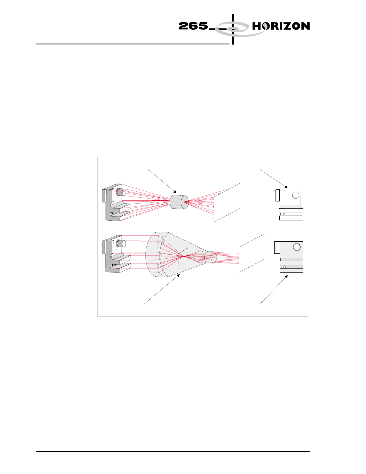
Telecentric Lens The optic unit within the camera assembly uses telecentricity to ensure that
board warping, distance between camera and board and the actual position of the
fiducials within the field of view do not affect the alignment accuracy.
6Engineering Specification Chapter Issue 1 May 00
ENGINEERING SPECIFICATION
KEY FEATURES
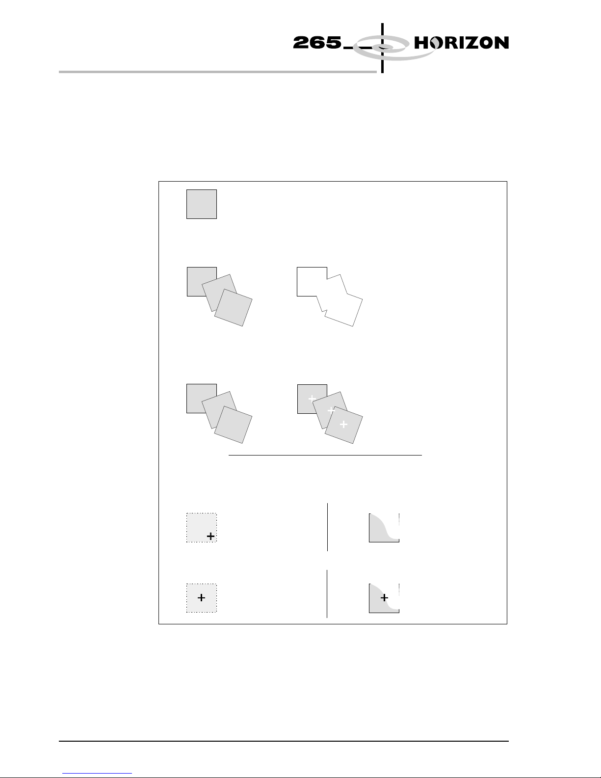
Conventional Lens Distorted Image
Undistorted Image
Telecentric Lenses Array
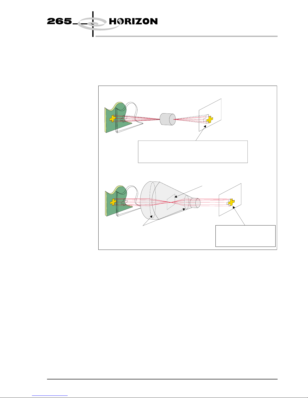
Variations in the distance between the optic unit and the board fiducials due to
uneven board surface are transparent when using telecentric lenses. With a
standard lens the diameter, centroid and position of a fiducial varies with this
distance, hence key elements in determining alignment of the board vary
depending on where the fiducials lie in the field of view.
Without DEK’s use of telecentric lenses, a pre-alignment stage would have to be
added to bring the fiducials into the centre of the field of view, before carrying
out a final alignment stage.
Chapter Issue 1 May 00 Engineering Specification 7
ENGINEERING SPECIFICATION
KEY FEATURES
Conventional Lens
If the board to camera distance varies due
to uneven board surface, the position and size
of the fiducial will vary accordingly.
Telecentric Lenses Array
Lens
Telecentric Stop
All fiducials seen as
identical wherever they
appear in the field of view.

Flat Lighting Essential for any vision system is to have the highest quality images with which
to process. Poor quality images may result in a degradation of image processing
leading to less accurate alignment and if inspection is used, misleading results.
DEK’s camera assembly fitted to the Horizon has been specifically designed to
enable low quality boards to be aligned and inspected with equal accuracy as
gold/copper boards. The lower quality boards have uneven Hot Air Solder
Levelled (HASL) pads and features.
The uneven surface texture and irregularities of these features and pads would
cause dead zones, ie areas where there is no light and hot spots of light caused by
reflection of light from solder pads and wet solder paste.
For high accuracy and reliable image processing DEK has incorporated a flat
lighting design within the camera assembly. This is achieved by utilizing two
light sources:
•Direct lighting - producing normal incidence and angles up to 25°
•Indirect/Oblique lighting - producing angles from 25° - 50°
8Engineering Specification Chapter Issue 1 May 00
ENGINEERING SPECIFICATION
KEY FEATURES
Light from a normal light source
HASL feature Surfaces not seen
by camera
Surfaces seen
by camera
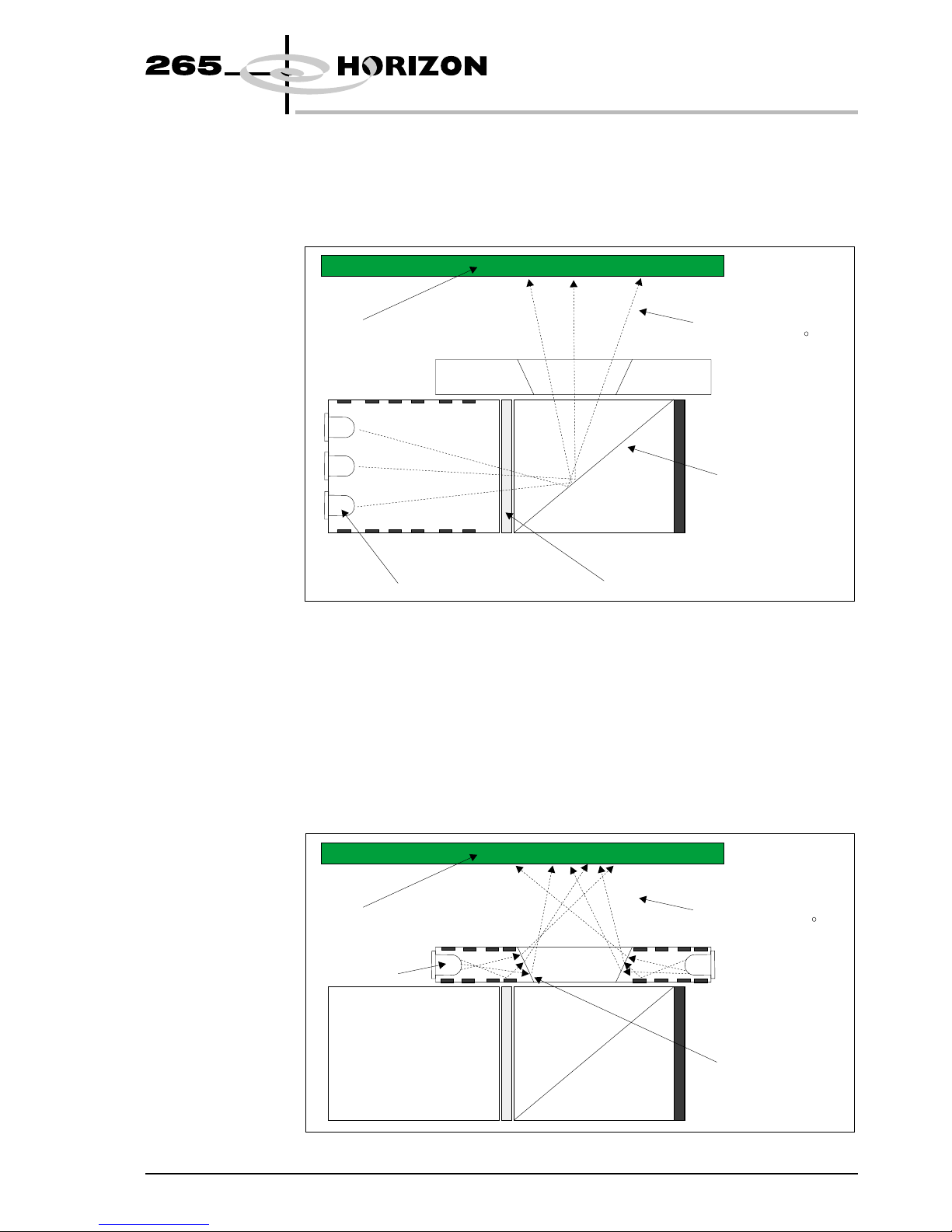
Direct lighting is achieved by a block of six LEDs shining through a diffuser to
produce a very uniform light source. The light is passed through a cube beam
splitter which increases the illumination and the range of angles reaching the
board.
Indirect /Oblique lighting is used in addition to direct lighting to produce light
paths between 25° and 50° to create uniform illumination, eliminating hot spots
of light.
An array of 12 LEDs sited in a polished ring around the lens aperture produce a
light source which is reflected and scattered by the polished surface and the
white paint of the assembly to the fine ground conical inner ring. This produces
very uniform illumination which is radiated in all directions providing a very
balanced illumination of the board.
Chapter Issue 1 May 00 Engineering Specification 9
ENGINEERING SPECIFICATION
KEY FEATURES
Board
LED Array
Inner Ring
Light paths
between 25 and 50
Board
LED Array Diffuser
50/50 Beam Splitter
Light paths
between 0 and 25
PatMax The Horizon machine uses PatMax® object location software to produce
accurate repeatable stencil to board alignment. PatMax interprets geometric
shapes within objects. A square fiducial is interpreted by PatMax as four
separate line segments. The advantages of the system are greater accuracy at
lower image quality. The object can be a different size, or different orientation to
the object learned. The target can be partly obscured and degraded.
10 Engineering Specification Chapter Issue 1 May 00
ENGINEERING SPECIFICATION
KEY FEATURES
= Learned fiducial
Non PatMax Object Location Software - Confused Objects
PatMax Object Location Software - Confused Objects
Target
Target
Interpretation
Interpretation
Result
Result
Fail to Locate
X
Successful Location
of Three Objects
Non PatMax Object Location Software
PatMax Object Location Software
Degraded Object Partial Object
Result
Fiducial Not Found
Result
Successful Location
of Fiducial
Result
Successful Location
of Fiducial
Result
Fiducial Not Found
Fiducials The Horizon uses the vision system to capture and process alignment marks or
fiducials to align the stencil to each board before it is printed. The alignment
marks or fiducials are produced as part of the artwork of the board and stencil, in
the same relative position. The information processed is used to correct stencil
to board alignment.
The Horizon has a library of synthetic fiducials of the most commonly found
shapes. The dimensions of these fiducials can be tailored by the operator to fit
the fiducials on the board and stencil. The fiducial on the stencil can be can be
different from the fiducial on the board. After the vision system has been taught
these fiducial parameters, it is able to search the field of view of the camera and
recognize any features which resemble fiducials.
After finding a shape it is assigned a score comparing its shape and size to the
shape and size of the fiducial in the vision system library. This score is set
between 1 and 999, the better the fit the higher the score.
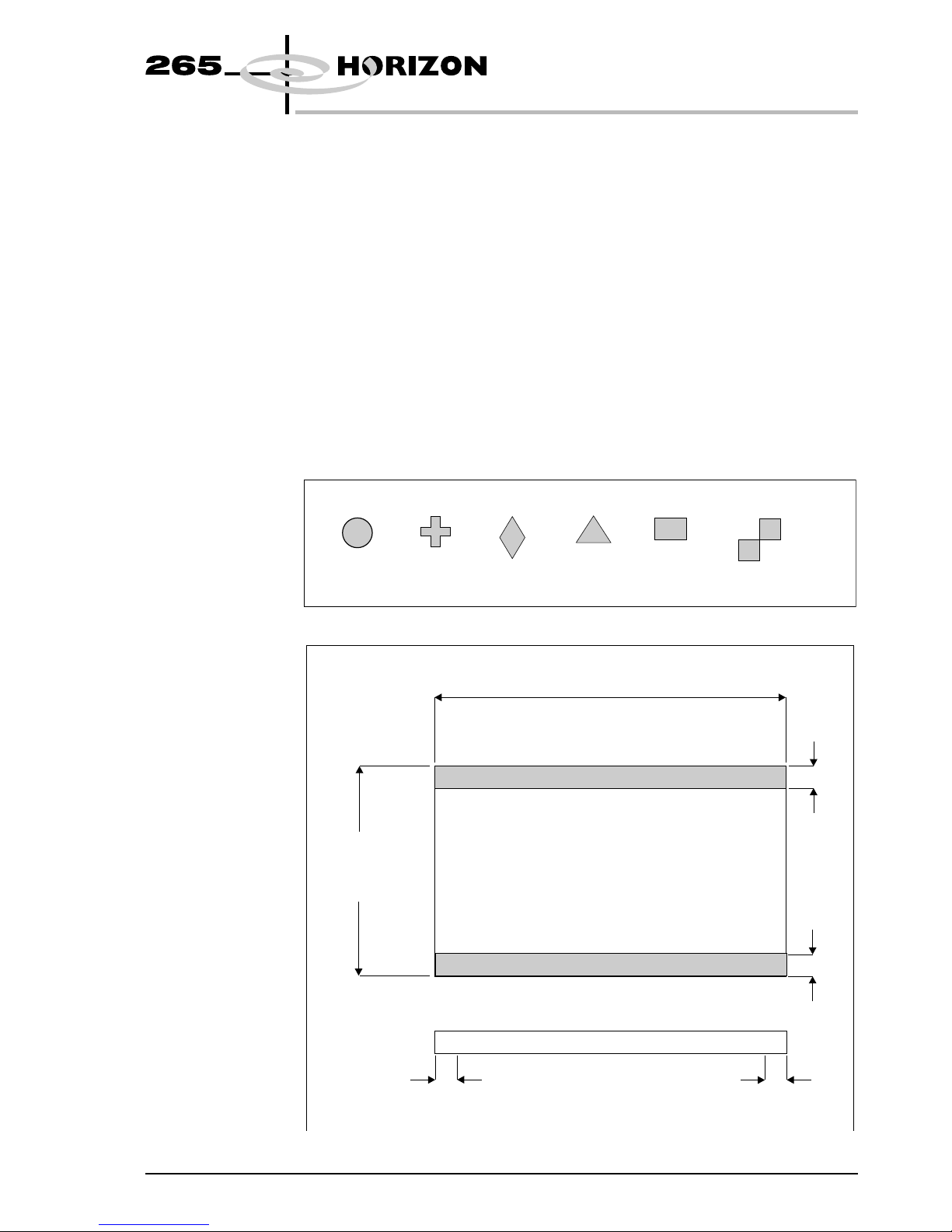
The fiducial shapes available is shown below:
Chapter Issue 1 May 00 Engineering Specification 11
ENGINEERING SPECIFICATION
KEY FEATURES
CIRCLE CROSS DIAMOND TRIANGLE RECTANGLE DOUBLE SQUARE
Board Length
Shaded Areas: No Printing and No Fiducials
Board
Width
3mm
3mm
3mmMustBeFree
of Underside Components
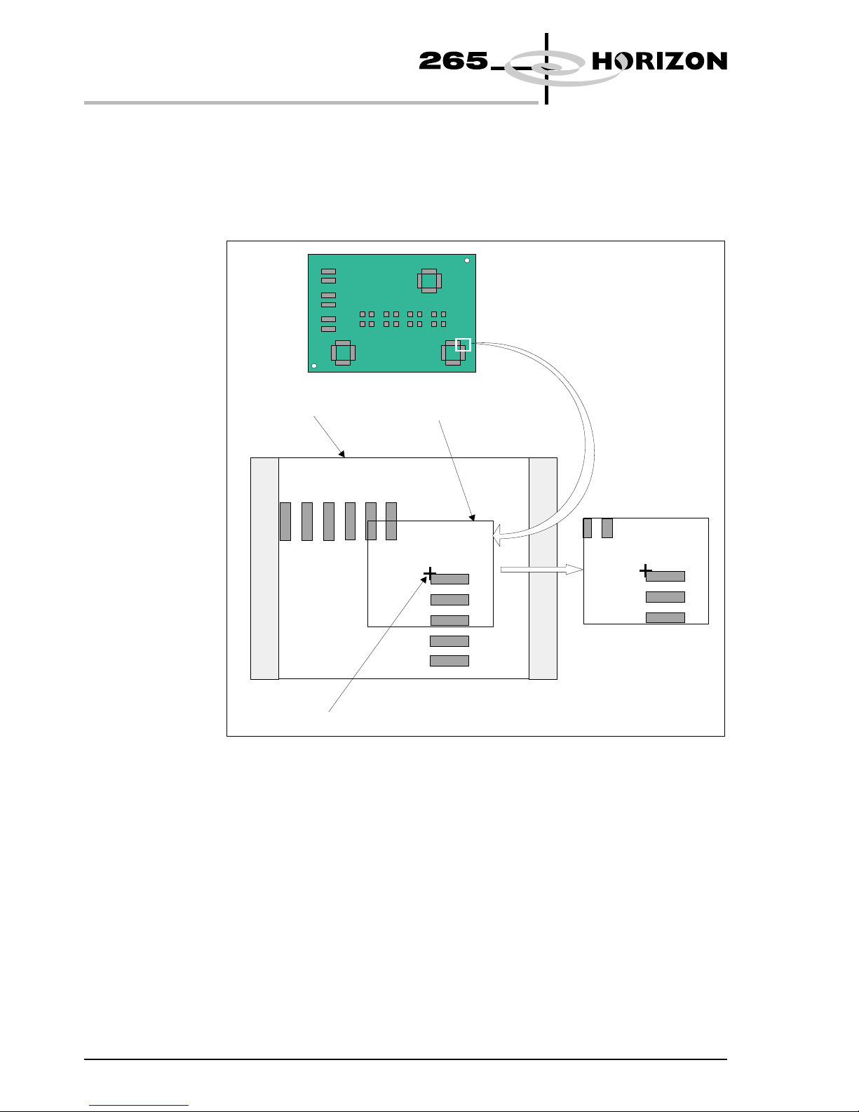
Video Model The video model is an alternative to using fiducials for stencil to board
alignment. Video model uses the correlation between the image of an area of the
stencil and the image of the same area of the board to align the two. This is useful
if the board or stencil has no fiducials or the condition of the fiducials does not
allow satisfactory recognition.
12 Engineering Specification Chapter Issue 1 May 00
ENGINEERING SPECIFICATION
KEY FEATURES
Field of View
Alignment Point
Sample Window
Video Model Fiducial

Windows NT The Horizon uses Windows NT operating system due to its inherent robust
nature. It is a globally accepted and industry standard user and programming
interface.
The main printer control, vision and user interface modules run under Windows
NT with the time critical, board handling and axis jogging routines running on
the real time operating system of the Baldor® Optimized Control NextMove
ISA card.
The Windows NT operating system provides built in networking compatible
with all industry standard networks as well as allowing standalone applications
such as QC Calc to be run onboard alongside the printer control system.
Chapter Issue 1 May 00 Engineering Specification 13
ENGINEERING SPECIFICATION
KEY FEATURES
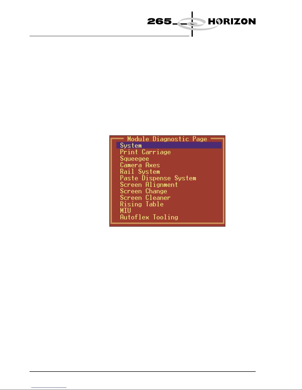
Diagnostics The Horizon machine contains a diagnostic module which enables the following
functions:
•Calibration of the machine
•Aid to machine fault diagnosis by means of
- Individual access and control of modules
- Access to the machine I/Os
This module can be password protected and can be enabled without the need to
initialize the Horizon. It allows the user to control the sequence of the machine
so that a particular module can be exercised.
Initiating the diagnostic module allows the user access to the following menu
options:
Selecting System allows access to the following functions:
•Digital and analogue I/Os
•Functioning of tricoloured beacon
•Facility to change various machine passwords
14 Engineering Specification Chapter Issue 1 May 00
ENGINEERING SPECIFICATION
KEY FEATURES
Table of contents


