Telpar MTP-1500 User manual

Page 1 of 64
MTP-1500 Modular Thermal Printer
User Manual
TELPAR
A Platinum Equity COMPANY
187 Crosby Road
Dover, New Hampshire 03820
Toll Free: 800-872-4886 (from the U.S.A. and Canada only)
603-750-7237
Fax: 603-742-9938
Website: www.telpar.com
E-mail: info@telpar.com
Part No. 090103-0010 (Rev. B - 05/03)

Page 2 of 64
Warranty
Telpar — Printer Limited Warranty
For one (1) year after shipment of the printer product to Buyer, Telpar warrants the product against defects in materials
and workmanship provided the product has been operated and maintained in accordance with manufacturer’s
operating and maintenance specifications. This warranty specifically excludes ribbons, paper and other consumable
items.
THIS WARRANTY IS IN LIEU OF ANY AND ALL OTHER WARRANTIES, EXPRESSED OR IMPLIED. TELPAR
MAKES NO OTHER WARRANTY AND BUYER SPECIFICALLY WAIVES ANY OTHER WARRANTIES, INCLUDING
WARRANTIES OF MERCHANTABILITY OR FITNESS FOR A PARTICULAR PURPOSE. THERE ARE NO
WARRANTIES THAT EXTEND BEYOND THOSE DESCRIBED HEREIN.
Telpar’s liability hereunder is limited to the repair or replacement of defective parts. This liability does not extend to
normal wear and tear. Telpar will, solely at its option, remedy all valid warranty claims either by:
(a) Repairing or replacing the defective unit at Telpar’s factory; or
(b) Repairing or replacing the defective subassembly at Telpar’s factory.
If so directed by Telpar, Buyer shall return the defective unit or subassembly, transportation prepaid by Buyer, to
Telpar’s factory. After repair or replacement has been accomplished, Telpar will return the unit or subassembly,
transportation prepaid by Telpar, to Buyer.
As a precondition to any warranty service, prior to return of any units or subassemblies to Telpar by Buyer, Buyer
must contact Telpar’s Order Administration Services and receive authorization in the form of a Return Material
Authorization (RMA) number. Telpar reserves the right to refuse any goods it has not previously authorized for return,
or any goods shipped without transportation prepaid.
No warranty shall apply to any damage resulting from or caused by Buyer, if Buyer shall make any changes,
modifications, additions or deletions of hardware, software or firmware in the Printer products sold hereunder without
Telpar’s advance written consent.
Upon receiving an RMA from Telpar, warranty service may be obtained by returning the merchandise, freight prepaid,
with a copy of your invoice to:
Telpar
187 Crosby Road
Dover, New Hampshire 03820 U.S.A.
ATTN.: Warranty Service Department.
Telephone: 800-872-4886 or 603-750-7237
Fax: 603-742-9938
Email: info@telpar.com
Upon inspection, Telpar will make necessary repairs or replacement and return the merchandise, shipping prepaid.

Page 3 of 64
Table of Contents
1 General................................................................................................................................... 9
1.1 Definitions........................................................................................................................ 9
1.1.1 Standard Mode versus Page Mode............................................................................. 9
1.1.2 Hex Dump Mode.......................................................................................................... 9
1.1.3 Explanation of Terms used throughout this manual................................................. 11
1.2 Applications.................................................................................................................... 11
1.3 Standard Features......................................................................................................... 12
1.4 Options for the MTP-1500 Series................................................................................ 13
1.5 Specifications................................................................................................................. 13
1.6 Power Supply Requirements....................................................................................... 13
1.6.1 Voltage: 24 VDC ±10%............................................................................................. 13
1.6.2 No requirement for external 5 VDC power supply..................................................... 13
1.6.3 3-Pin Hosiden Connector on Printer for Power Supply Connection......................... 13
1.7 Telpar Roll Paper for MTP-1500 Series...................................................................... 14
2 Operator Instructions....................................................................................................... 15
2.1 Unpacking and Inspection............................................................................................ 15
2.2 Paper Loading................................................................................................................ 15
2.2.1 Side-Loading Roll...................................................................................................... 15
2.2.2 Black Mark Sensors Load......................................................................................... 15
2.3 Paper Jam....................................................................................................................... 17
2.3.1 Head Open Lever...................................................................................................... 17
3 Installation........................................................................................................................... 19
3.1 Self Test Mode............................................................................................................... 19
4 Interface Specifications................................................................................................... 21
4.1 General........................................................................................................................... 21
4.1.1 Setting of DIP Switches and MEMORY Switches..................................................... 21

Page 4 of 64
4.1.2 LEDs and Error Indication......................................................................................... 23
4.2 Control Codes and Control Sequences List.............................................................. 24
4.3 Control Codes and Control Sequences Definition................................................... 27
4.3.1 General Usage Print Commands.............................................................................. 27
4.3.2 Status Commands.................................................................................................... 31
4.3.3 Bar Code Commands............................................................................................... 31
4.3.4 Counter Commands.................................................................................................. 32
4.3.5 Top of Form Commands........................................................................................... 34
4.3.6 Page Mode Commands............................................................................................ 34
4.3.7 NV Memory and Down Load Bit Images Commands............................................... 36
4.3.8 Seldom Used Commands......................................................................................... 38
4.4 Descriptions of Commands.......................................................................................... 41
4.4.1 Set Print Mode........................................................................................................... 41
4.4.2 Set Bit Image Mode................................................................................................... 41
4.4.3 Set Raster Bit Image Mode....................................................................................... 43
4.4.4 Status Commands.................................................................................................... 44
4.4.5 Enable/Disable Auto Status Back (ASB) mode........................................................ 45
4.4.6 Status Bytes Transmitted.......................................................................................... 45
4.4.7 Bar Code Command................................................................................................. 46
4.4.8 GS k +m +n +d1dn [1D 6B +m +n (DATA)]............................................................ 47
4.5 Serial (RS232C) Interface............................................................................................. 49
4.5.1 Serial (RS232C) Interface Specification................................................................... 49
4.5.2 Serial I/O Connector.................................................................................................. 49
4.5.3 Flow Control.............................................................................................................. 50
4.6 Centronics Parallel (IEEE-1284) Interface.................................................................. 51
4.6.1 Parallel I/O Connector............................................................................................... 51
5 Specifications..................................................................................................................... 53

Page 5 of 64
5.1 Features.......................................................................................................................... 53
5.2 General Specifications +++ redo................................................................................ 54
5.3 Character Sets............................................................................................................... 55
5.3.1 Overview.................................................................................................................... 55
5.3.2 PC437 U.S.A., Standard Europe Character Set....................................................... 56
5.3.3 Katakana Character Set............................................................................................ 57
5.3.4 PC850 (Multilingual) Character Set........................................................................... 58
5.3.5 PC860 (Portuguese) Character Set.......................................................................... 59
5.3.6 PC863 Canadian French Character Set................................................................... 60
5.3.7 PC865 Nordic Character Set.................................................................................... 61
5.3.8 WPC 1252 Character Set......................................................................................... 62
5.3.9 PC866 Cyrillic #2 Character Set............................................................................... 63
5.3.10 PC852 Latin 2 Character Set.................................................................................... 64
5.3.11 PC858 Euro Character Set....................................................................................... 65
5.3.12 Space Page Character Set....................................................................................... 66
5.3.13 Overseas Character Set........................................................................................... 67
5.3.14 International Character Set........................................................................................ 68
5.4 Dimensional Drawings of MTP-1530 (80 mm) Version.............................................. 69
5.4.1 Dimensional Drawing of MTP-1530 (80 mm) Version.............................................. 69
5.4.2 Dimensional Drawings of MTP-1532 (82.5 mm) Version......................................... 70

Page 6 of 64
List of Figures
Figure 1 Print Sample.................................................................................................................... 10
Figure 2 Hex Dump of Print Sample............................................................................................ 10
Figure 3 3-Pin Hosiden Power Supply Connector....................................................................... 13
Figure 4 Black Mark Specifications.............................................................................................. 16
Figure 5 - MTP-1500 with Cutter Mechanism closed.................................................................... 17
Figure 6 - MTP-1500 with Cutter Mechanism open...................................................................... 18
Figure 7 MTP-1500 Self Test Printout.......................................................................................... 20
Figure 8 Counter Commands...................................................................................................... 33
Figure 9 Print Mode Settings........................................................................................................ 41
Figure 10 Status Commands....................................................................................................... 44
Figure 11 Fourth Status Byte Transmitted................................................................................... 46
Figure 12 - Serial I/O Connector +++ redo as DE9P.................................................................... 49
Figure 13 - Parallel I/O Connector +++ Change dwg to CENT............................................ 51
Figure 14 Overview of Character Sets......................................................................................... 55
Figure 15 PC437 U.S.A., Standard Europe Character Set........................................................... 56
Figure 16 Katakana Character Set (80-FF hex)............................................................................ 57
Figure 17 PC850 Multilingual Character Set................................................................................. 58
Figure 18 PC860 Portuguese Character Set............................................................................... 59
Figure 19 PC863 Canadian French Character Set....................................................................... 60
Figure 20 PC865 Nordic Character Set........................................................................................ 61
Figure 21 WPC 1252 Character Set............................................................................................. 62
Figure 22 PC866 Cyrillic#2 Character Set.................................................................................... 63
Figure 23 PC852 Latin 2 Character Set........................................................................................ 64
Figure 24 PC858 Euro Character Set.......................................................................................... 65
Figure 25 Space Page Character Set.......................................................................................... 66

Page 7 of 64
List of Tables
Table 1 Current Requirements..................................................................................................... 13
Table 2 - DIP Switch 1 (DSW1) Settings...................................................................................... 21
Table 3 - DIP Switch 2 (DSW2) Settings +++ rearrange in order................................................ 22
Table 4 Control Codes and Control Sequences........................................................................... 26
Table 5 List of Control Codes and Control Sequences Locations................................................ 27
Table 6 General Usage Print Commands.................................................................................... 30
Table 7 Response to Status Commands.................................................................................... 31
Table 8 Status Commands......................................................................................................... 31
Table 9 - Bar Code Commands.................................................................................................... 32
Table 10 Top of Form Commands................................................................................................ 34
Table 11 – Page Mode Commands.............................................................................................. 36
Table 12 – NV Memory Commands.............................................................................................. 37
Table 13 - Seldom Used Commands........................................................................................... 40
Table 14 Set Bit Image Mode........................................................................................................ 41
Table 15 Set Raster Bit Image Mode............................................................................................ 43
Table 16 First Status Byte Transmitted........................................................................................ 45
Table 17 Second Status Byte Transmitted................................................................................... 45
Table 18 Third Status Byte Transmitted....................................................................................... 46
Table 19 Bar Code Commands.................................................................................................... 46
Table 20 Bar Code Command Values.......................................................................................... 47
Table 21 - Serial (RS232C) Interface Specification..................................................................... 49
Table 22 - Serial (RS232C) Interface Pin Assignments............................................................... 50
Table 23 - Parallel Interface Pin Assignments.............................................................................. 52
Table 24 - General Specifications................................................................................................. 54
Table 25 - Default Character Set.................................................................................................. 66
Table 26 - Overseas Character Set.............................................................................................. 67

Page 8 of 64
Table 27 - International Character Set.......................................................................................... 68

Page 9 of 64
1 General
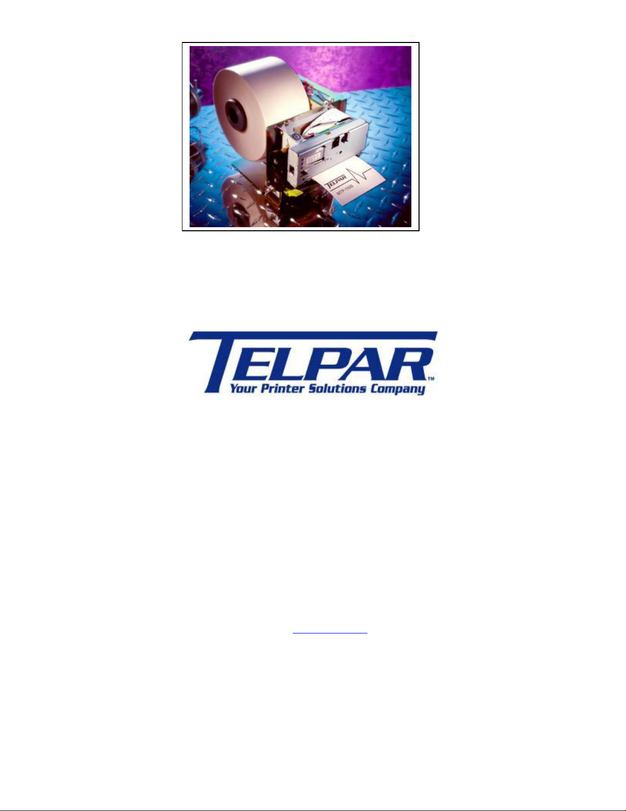
The MTP-1500 series of modular thermal printers is designed specifically for the high performance, size and durability
requirements of cut and drop applications. The compact size and high performance characteristics, coupled with its
rugged design also make it ideal for the kiosk environment.
Four models make up the MTP-1500 Series:
· MTP-1530-SF - 80 mm (3.15 in) paper width , Full Cut . (Part # 901033-0006)
· MTP-1530 -SP - 80 mm (3.15 in) paper width , Partial Cut. (Part # 901034-0006)
· MTP-1532 -SF – 82.5 mm (3.25 in) paper width , Full Cut. (Part # 901033-0010)
· MTP-1532 -SP – 82.5 mm (3.25 in) paper width , Partial Cut. (Part # 901034-0010)
1.1 Definitions
1.1.1 Standard Mode versus Page Mode
Standard mode means printing data as it is received like most serial mode printers. If data is not received fast enough
to keep the printer busy, the printer will print data it has received and then stop and wait for more data to be received
so it can print a little more. This is the most commonly used mode of operation but anytime the printer has to stop and
then restart, there is a possibility of reduced print quality.
· Page mode means that all the data to be printed on a page is received before printing begins so once the
printing process starts, an entire page is printed at full speed.
· Most commands and parameters are the same for both standard mode and page mode but the ESC SP, ESC 2,
and ESC 3 are set independently in standard mode and page mode, See section 4.2 Control Codes and Control
Sequences List .
· Some commands apply only to page mode and some commands are ignored in page mode.
See Table xxx +++ add bookmark to COMMAND LIST table.
· Ladder bar codes can be printed only in page mode.
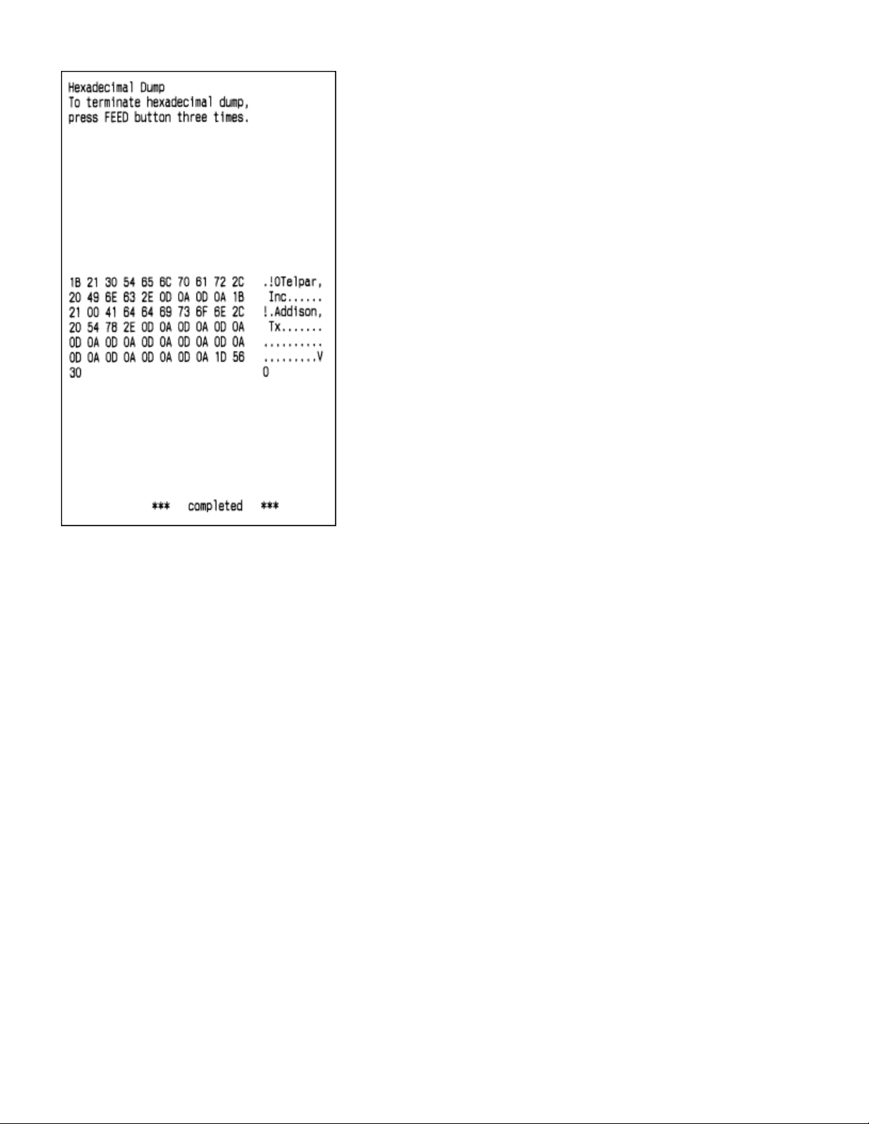
1.1.2 Hex Dump Mode
This function is sometimes useful for diagnosis of application programs when the printer does not perform as
expected. In hex dump mode, the printer prints the hexadecimal code for each character received rather than
processing the data as printable text and as control commands. The exception is that DLE EOT (real time STATUS
request) and DLE ENQ (Real time request to printer) are executed as received even in hex dump mode. The
hexadecimal notation is printed at 10 characters per line on the left side of the page and the printable characters (when
possible) are printed on the right side of the page. Control codes print as periods on the right side section of the
printout to help locate specific areas of the message to see what codes were actually received by the printer. After all
data has been sent to the printer, pressing the paper feed button will flush the buffer and print the last line of data
received.
Hex dump mode is initiated in any of three ways:
1) Open the platen, hold the paper feed button down, turn on power, then close the platen and release the paper
feed button.
2) Set DIP switch DPSW2 position 5 ON and then turn on power.
3) Send the appropriate GS ( A command. On entering hex dump mode, the printer prints a 4 line header
“Hexadecimal Dump”, a blank line, “To terminate hexadecimal dump”, “press FEED three times.”
Hex dump mode is terminated by
1) pressing the paper feed button three times in quick succession or
2) by turning DIP switch DPSW2 position 5 OFF and turning power back on.
Print Sample
Figure 1 Print Sample

Page 10 of 64
Figure 2 Hex Dump of Print Sample
1.1.3 Explanation of Terms used throughout this manual
Receive buffer – Receives data from the host and stores the data temporarily until it can be processed to the print
buffer or processed as otherwise required.
Print buffer – Stores the image data to be printed.
Start of line – There is no print data in the print buffer and the print position is not specified by ESC $ or ESC \. Many
commands are effective only at the start of line.
Printable area – In standard mode the length in the horizontal direction is: 80 mm (640 dots per line/8 dots per mm)
for the 82.5 mm paper width version, 72 mm (576 dots per line/8 dots per mm) for the 80 mm paper width version. In
page mode the length in the horizontal direction is: 80 mm (640 dots per line/8 dots per mm) for the 82.5 mm paper
width version, 72 mm (576 dots per line/8 dots per mm) for the 80 mm paper width version. In page mode the length in
the vertical direction is: 83 mm (664 dots per line/8 dots per mm) for the 82.5 mm paper width version, 92 mm (738
dots per line/8 dots per mm) for the 80 mm paper width version.
Printing area – Printing range set by command. The printing area must be less than or equal to the printable area.
MBS – Most Significant Bit of a byte of data.
LBS – Least Significant Bit of a byte of data.
OFF LINE – There is no switch for setting the printer On Line or Off Line. The printer automatically goes Off Line
a. From power on (or reset through the I/O connector) until the printer is ready to receive data.
b. During self test.
c. While feeding paper with the paper feed button.
d. When out of paper.
e. When the print platen is open.
f. During a macro execution and in standby status.
g. When an error occurs.
1.2 Applications
· Parking ticket dispensing
· Automated Teller Machines (ATMs)

Page 11 of 64
· Gaming receipts
· Interactive media kiosks
1.3 Standard Features
· Direct thermal printing
· Interfaces: Serial (RS232) and parallel (IEEE1284) .
· Paper widths - specified at time of order:
· Model MTP-1530 : 80 mm (3.15 in)
· Model MTP-1532 : 82.5. mm (3.25 in)
· Full or Partial Cut – specified at time of order.
· All metal construction
· Adjustable paper low sensor
· Paper auto load function
· ESC/POS [1] The commands conform to ESC/POS, which is a standard in the distribution industry.
· Print speed of up to 150 mm/sec (5.9 in/sec); 1200 dot lines/second)
· DIP switches accessible without removing cover.
· Paper capacity : 152 mm (6 in) diameter roll with 50 mm diameter core
· Overall size including 152 mm (6 inch) diameter roll of paper :
185.67 mm x 149.45 mm x 243.17 mm(7.31 in H x 5.88 in W x 9.57 in D)
· Inverted print mode
· Character code tables: PC437 (USA, default), Katakana, PC850 (Multilingual), PC860 (Portuguese), PC863
(Canadian-French), PC865 (Nordic), WPC1252, PC866 (Cyrillic2), PC852 (Latin2), PC858 (Euro), Space page.
· International character set : Control Boards, have the following: U.S.A., France, Germany, England, Denmark (2
choices), Sweden, Italy, Spain (2 choices), Japan , Norway, Latin America, Korea.
· Barcode embedded symbologies: UPC-A , UPC-E, JAN(EAN) 13, JAN(EAN)8 , 3 of 9 , ITF , CODABAR,
Code93, and Code128 . Ladder Bar codes can be printed when using Page Mode.
· Bit image mode
· Reverse video mode
· Underline printing
· Continuous roll paper
· Page Mode
· Two character font sizes. Each can be printed from 1 to 8 times normal width and/or 1 to 8 times normal height.
· “Smoothing” command (see GS b) – applies only in Page mode.
1.4 Options for the MTP-1500 Series
· Microsoft®Windows®driver. [2]
· Black Mark sensing.
1.5 Specifications
· Resolution : 8 dots/mm (203 dots/in).
· Paper thickness : 0.056 mm to 0.15 mm maximum (0.0022 in to 0.0059 in).
· Operating temperature : 0o C to 55o C (32o F to 131o F).
· Storage temperature : -25o C to 70o C (-13o F to 158o F).
· Operating humidity : 10-85% RH (non-condensing).
· Peak current for head drive is 14A at 150 mm/second.
· Weight : Standard configuration without paper +++ kg (+++ lbs.).
· Expected life of mechanism: 15 million lines.
· Expected life of cutter: 1 million cuts.
1.6 Power Supply Requirements
1.6.1 Voltage : 24 VDC ±10%
Current Requirements

Page 12 of 64
High Speed Mode 14 Amps peak 9 Amps average
Divided Energy Mode 11.5 Amps peak 7 Amps average
Stand-by 0.1 Amps
Table 1 Current Requirements
1.6.2 No requirement for external 5 VDC power supply
The 5 VDC for logic is supplied from the 24 VDC, by a regulator internal to the printer.
1.6.3 3-Pin Hosiden Connector on Printer for Power Supply Connection
Figure 3 3-Pin Hosiden Power Supply Connector

Page 13 of 64
1.7 Telpar Roll Paper for MTP-1500 Series
Thermal sensitive coating is on the “inside” of the roll.
· For MTP-1530 ;152 mm (6 in) outside diameter, 80 mm (3.15 in) wide, length 180 m (590 ft) P/N 251103-8006.
· For MTP-1532 :152 mm (6 in) outside diameter, 82.5 mm (3.25 in) wide, length 180 m (590 ft) - P/N 251103-
8206.
Specific to Thermal Printers: Telpar, Inc. does not warranty damages to the thermal print head as a result of printing
with thermal paper not specified or approved by Telpar, Inc.
2 Operator Instructions
2.1 Unpacking and Inspection
Carefully unpack and inspect your MTP-1500 for any damage that may have occurred in transit. Should any damage
have occurred, notify Telpar, Inc., save the shipping carton and packing materials , and file a damage claim with the
carrier. Specify the nature and the extent of the damage. Before installing or operating the printer, check the following:
Printer mechanism and paper path are clear of all packing materials or other foreign matter.
Paper is installed. DO NOT OPERATE the printer without paper. Refer to Section 2.2 - Paper Loading page 15
for paper loading instructions.
2.2 Paper Loading
2.2.1 Side-Loading Roll
The MTP-1500 series printer is configured as a side-loading printer . Slide roll of paper over spindle with paper fed
under the bottom toward paper slot (front of unit).
To load paper , turn on the power and feed the straight edge of the paper into the paper guide. AUTOLOAD will
automatic load paper once it is fed into the paper guide. Once paper has been initially loaded, the paper feed button
may be used. Ensure that the paper is installed correctly and feeding properly with the thermal side facing up.
2.2.2 Black Mark Sensors Load
The MTP-1500 series printer may be used with the optional Black Mark Sensor. This requires the use of a pre-printed
Top of Form (TOF) Mark or Black Mark on the form. Dip switch SW1 position 1 must be set to the ON position to
enable black mark operation.
If DIP switch DSW1 position 1 is turned on to enable the Black Mark sensor when the printer is loaded with plain
paper, at Power On the printer will feed about 17.5 inches of paper looking for a Black Mark and then go to an error
mode since it did not find a Black Mark.
To load paper , turn on the power and feed the straight edge of the paper into the paper guide. Ensure that the paper
is installed correctly and feeding properly with the thermal side facing up.
If using perforated paper, the perforation should be fed at least 1.27 mm (0.05 in) past the cut line to avoid a jam at the
cutter. The black mark may extend across the full width of the paper. (TBD)
See Figure 4 Black Mark Specifications
See section 4.3.5 Top of Form Commands

Page 14 of 64
NEED NEW DRAWING
Figure 4 Black Mark Specifications
See section 4.3.5 - Top of Form Commands for additional information.
2.3 Paper Jam
In the event of a paper jam condition do not force paper into the unit, or try to pry the paper out of the unit, this may
damage the thermal print mechanism . Caution should be exercised when working next to the cutter mechanism , the
blades are sharp and may cause serious injury.
To release paper:
Turn off power to the printer.
Push the Head Open lever to the down position.
(See Figure 6 - MTP-1500 with Cutter Mechanism open ) Paper can be removed at this time. Once paper is
cleared from the mechanism, return the Head Open lever to the up position.
2.3.1 Head Open Lever
The Head Open lever is located at the left front of the printer mechanism. The up position is ready to print. The down
position lifts the print head off of the platen roller for manually inserting paper or for clearing a paper jam. The down
(head open) position signals the microprocessor that the head is open so that no printing will occur.
Figure 6 - MTP-1500 with Cutter Mechanism open
3 Installation
3.1 Self Test Mode
The MTP-1500 has a self-test mode that will print and cut a sample ticket.
To place the unit into self-test mode , first turn power switch off, then press and hold the FEED push button switch and
place the POWER switch in the ON position.. Release the switch after printing starts.See Figure 7 MTP-1500 Self
Test Printout on page 20 . The first part of the self test message prints several fields showing how the printer is
configured. Following the first part of the self test, you have the option of pressing the paper feed button to print a
“barber pole” pattern print test or turning power off and back on to terminate the self test The printer goes to the off-line

Page 15 of 64
(BUSY) state when self test starts and remains off-line until self test is finished due two either of these actions. All
electrical/mechanical portions of the printer are exercised and checked by this action, except for the serial interface or
parallel interface components.
Figure 7 MTP-1500 Self Test Printout
4 Interface Specifications
4.1 General
The MTP-1500 Series includes a Serial RS232 interface and a IEEE1284 Parallel interface.

Page 16 of 64
4.1.1 Setting of DIP Switches and MEMORY Switches
4.1.1.1 DSW1 – DIP Switch
DIP Switch 1 (DSW1) Settings
Item Bit No Setup status Setup state Setup
before
shipping
Bit 7 Bit 8
OFF OFF
38400 bps
ON OFF 19200 bps
OFF ON 9600 bps
Serial-interface-
communication baud
rate setting
8,7
ON ON 4800 bps
19200
Even/odd parity
selection
6 OFF Odd parity ODD
Parity use selection 5 OFF No parity No Parity
OFF DTR/DSR
control
ON Xon/Xoff
control
ON Even parity
Serial interface
handshaking
4
ON Parity used
DTR
Bit 3 Bit 2
Interface
Selection
3,2
OFF OFF
Parallel
interface
Parallel
OFF Disabled
ON Enabled
Black Mark sensor 1
ON,OFF Serial
interface
Disabled
Add to table for 3,2 Optional? Either,ON
Table 2 - DIP Switch 1 (DSW1) Settings

Page 17 of 64
4.1.1.2 DSW2 – DIP Switch 2
DIP Switch 2 (DSW2) Settings
Item Bit
No.
Setup Status Setup State Setup
before
shipping
OFF No resetParallel I/O pin 31 =
RESET
8
ON Reset signal on
pin 31
OFF
OFF No resetSerial I/O pin 6 =
RESET
7
ON Reset signal on
pin 6
OFF
Factory use 6 OFF
5 OFF Normal NormalOperation mode
selection ON Hex Dump
Bit 3 Bit 4
ON ON Slightly light
OFF OFF Normal
ON OFF Slightly dark
Print density
selection
3,4
OFF ON Dark
Normal
Bit 1 Bit 2
OFF OFF MTP-1532
ON OFF MTP-1530
OFF ON 60 mm
Printer mechanism
selection
1, 2
ON ON 58 mm
A
s required
for mech
Table 3 - DIP Switch 2 (DSW2) Settings
4.1.1.3 There are 8 MEMORY Switches, only two are currently used
Memory Switch 1
Position Function
ON Auto line feed enabled (Parallel interface only)#5
OFF Auto line feed disabled
ON Receive error is ignored (serial interface only)#4
OFF Receive error prints “?” (serial interface only)
ON BUSY condition when buffer is full#3
OFF BUSY when buffer is full or when OFF-LINE
Memory Switch 8
Position Function
ON Cutter is NOT installed#4
OFF Cutter is installed
ON Reverse paper feeding is enabled (See NOTE)#3
OFF Reverse paper feeding is disabled
ON Divided energy print mode#1
OFF High speed print mode
Note: Not all printer mechanisms allow reverse paper feeding. If reverse feeding is allowed, after cutting the paper
with a GS V command, paper feeds backwards. The print starting position adjustment with GS ( F can be set to the
backward direction relative to the cutting position. In this case, the maximum backward feed length is 14 mm (112 *
0.125mm).
4.1.2 LEDs and Error Indication
Three LEDs (D3, D5, and D6) are located above Dip switch DSW1.

Page 18 of 64
D3 is the green POWER LED, ON means power is stable and the printer is ready for operation. OFF means power
in not stable.
D5 is a red PAPER OUT LED, OFF means paper is installed and the printer is ready for operation. ON means
there is no paper installed in the printer mechanism (or the paper low sensor if selected). The PAPER OUT LED blinks
steadily to specify that self test has finished the first part of printing and that the user can press the PAPER FEED
button to print the “barber pole” character print part of the self test. The PAPER OUT LED also blinks steadily to
specify that a MACRO is waiting for the user to press the PAPER FEED button to continue it’s execution (macro stand-
by mode).
D6 is a red ERROR LED. OFF means there are no errors and the printer is ready for operation. ON indicates the
printer is OFF LINE (except during paper feeding using the FEED button, during self-test printing, and in the error
state). The ERROR LED blinks a defined pattern every 5.12 seconds to notify the user of various error conditions.
When the LED is normally OFF and blinks ON, an error is indicated which may be recoverable. . When the LED is
normally ON and blinks OFF, an error is indicated which in not recoverable. For any error that is not recoverable,
power should be turned off as soon as possible.
Blink Rate Error Description Recovery method
Continuous Print head
Temperature
The temperature
has exceeded 70
degrees C
A
utomatic when the
print head cools off.
1 blink ON Cutter error The cutter has
failed to complete
a cut
Recovers by DLE
ENQ after the cutter
Jam has been
corrected
1 blink OFF PCB error The printer
mechanism is not
connected or the
internal wiring in
incorrect.
Turn power off and
check connections
between the printer
mechanism and the
controller board.
2 blinks ON Black Mark No Black Mark
was detected
Recovers by DLE
ENQ. within ???.
2 blinks OFF R/W error The CPU has
detected a
memory R/W error
Cycle power off and
on to see if the
error goes away.
3 blinks OFF High voltage The power supply
voltage is too high
Turn power OFF,
correct the problem
before turning back
on.
4 blinks OFF Low voltage The power supply
voltage is too low.
Turn power OFF,
correct the problem
before turning back
on.
5 blinks OFF CPU error A program
execution error
Cycle power off and
on to see if the
error goes away.
6 blinks ON Platen open The Print platen is
open
Recovers by DLE
ENQ after the
platen
is closed.
4.2 Control Codes and Control Sequences List
Location of
Definition
Class Standard
mode
Page
mode
HT Horizontal tab General Execute Yes Yes
LF Print and line feed General Execute Yes Yes
FF PAGE MODE, print and
return to standard mode
PAGE Execute Ignored Yes

Page 19 of 64
Black Mark mode, print and
feed to print starting
position (Black Mark)
General, Top of
Form
Execute Yes Disabled
CR Print and carriage return General Execute Yes Yes
CAN Cancel print data PAGE Execute Ignored Yes
DLE EOT Real time status request STATUS Execute Yes Yes
DLE
ENQ
Real time request to printer General Execute Yes Yes
ESC Escape sequence header --- --- --- ---
FS FS sequence header --- --- --- ---
GS GS sequence header --- --- --- ---
ESC FF Print data PAGE Execute Ignored Yes
ESC SP Set right side character
spacing
General Setting Yes Yes
ESC ! Set print mode(s) General Setting Yes Yes
ESC$ Set absolute print position General, PAGE Execute Yes Yes
ESC % Select/cancel user-defined
character set
Seldom Setting Yes Yes
ESC & Define user-defined
characters
Seldom Setting Yes Yes
ESC * Select bit image mode General Execute Yes Yes
ESC - Turn underline on/off General Setting Yes Yes
ESC 2 Select default line spacing General Setting Yes Yes
ESC 3 Set line spacing General Setting Yes Yes
ESC ? Cancel user-defined
characters
Seldom Setting Yes Yes
ESC @ Initialize printer General Execute,
Setting
Yes Yes
ESC D Set horizontal tabs General Setting Yes Yes
ESC E Turn emphasized on/off General Setting Yes Yes
ESC G Turn double-strike on/off General Setting Yes Yes
ESC J Print and feed paper General Execute Yes Yes
ESC L Select PAGE MODE PAGE Execute Start line Ignored
ESC M Select character font General Setting Yes Yes
ESC R Select international
character set
General Setting Yes Yes
ESC S Select standard mode PAGE Execute Ignored Yes
ESC T Select print direction PAGE Setting Value Yes
ESC V Turn rotated print on/off General Setting Yes Value
ESC W Set printing area PAGE Setting Value Yes
ESC \ Set relative print position General, PAGE Execute Yes Yes
ESC a Select justification General Setting Start line Value
ESC c 3 Select paper sensors to
output paper out signal
General Setting Yes Yes
ESC c 4 Select paper sensors to
stop printing
General Setting Yes Yes
ESC c 5 Enable/disable panel
buttons
General Setting Yes Yes
ESC d Print and feed n lines General Execute Yes Yes
ESC t Select character code table General Setting Yes Yes
ESC { Turn inverted print on/off General Setting Start line Value
FS p Print NV bit image NV & DL Execute Yes Disabled
FS q Define NV bit image NV & DL Setting Start line Disabled
GS FF Feed paper to Black Mark Top of Form Execute Yes Yes

Page 20 of 64
GS ! Select character size General Setting Yes Yes
GS $ Set absolute vertical print
position
PAGE Execute Ignored Yes
GS * Define download bit image NV & DL Setting Yes Yes
GS ( A Execute test print General Execute Yes Ignored
GS ( E User setup commands Seldom Execute,
Setting
Start line Disabled
GS ( F Set adjustment values Seldom Setting Yes Yes
GS ( M Customize printer control
values
Seldom Setting Start line Value
GS / Print download bit image NV & DL Execute Empty Yes
GS : Start/end macro definition Seldom Execute,
Setting
Yes Yes
GS B Set reverse video on/off General Setting Yes Yes
GS C 0 Select counter print mode Counter Setting Yes Yes
GS C 1 Select count mode (A) Counter Setting Yes Yes
GS C 2 Set counter Counter Setting Yes Yes
GS C ; Select count mode (B) Counter Setting Yes Yes
GS E Select head control method Seldom Setting Yes Yes
GS H Select printing position of
HRI characters
Bar Code Setting Yes Yes
GS I Transmit printer ID Status Execute Yes Yes
GS L Set left margin General Setting Start line Value
GS T Set print position to
beginning of line
General Execute Yes Ignored
GS V Select cut mode and cut
paper
General Execute Start line Yes
GS W Set printing area width General Setting Start line Value
GS \ Set relative vertical printing
position
PAGE Execute Ignored Yes
GS ^ Execute macro Seldom Execute Yes Yes
GS a Enable/disable Auto Status
Back (ASB)
Status Execute,
Setting
Yes Yes
GS b Turn smoothing mode
on/off
Setting Yes Yes
GS c Print counter Counter Execute Yes Yes
GS f Select font for HRI
characters
Bar Code Setting Yes Yes
GS h Set bar code height Bar Code Setting Yes Yes
GS k Print bar code Bar Code Execute Empty Yes
GS r Transmit status Status Execute Yes Yes
GS v 0 Print raster bit image General Execute Empty Disabled
GS w Set bar code width Bar Code Setting Yes Yes
Table 4 Control Codes and Control Sequences
List of Control Codes and Control Sequece Locations
Control Codes Control Sequences
Bar Code See 4.3.3 Bar Code Commands page 31
Counter See 4.3.4 Counter Commands page 32
General See 4.3.1 General Usage Print Commands page27
NV & DL See 4.3.7 NV Memory and Down Load Bit Images
Commands page 36
Page See 4.3.6 Page Mode Commands page 34
Seldom See 4.3.8 Seldom Used Commands page 38
Status See 4.3.2 Status Commands page 31
Table of contents
Other Telpar Printer manuals

Telpar
Telpar SP-327 User manual

Telpar
Telpar MTP-2232 User manual

Telpar
Telpar SP-328 User manual

Telpar
Telpar MTP7632 Owner's manual

Telpar
Telpar SP-401 Series User manual

Telpar
Telpar MTP-1530II User manual

Telpar
Telpar MTP-2822 User manual

Telpar
Telpar MTP-600 Series User manual

Telpar
Telpar SP-5000 User manual