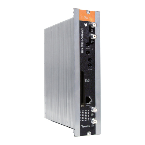
DekTec DTE-3114 User manual

DTE-3114
Networked Quad QAM Modulator
USER MANUAL
Augustus 2013

DTE-3114 –Networked Quad QAM Modulator
USER MANUAL
2
Table of Contents
1. Introduction ............................................................................................................................4
1.1 General description ...........................................................................................................4
1.2 Block diagram ...................................................................................................................4
1.3 Applications.......................................................................................................................5
1.4 Limitations.........................................................................................................................5
1.5 List of Abbreviations ...........................................................................................................6
2. Installation ..............................................................................................................................8
2.1 Physical layout ...................................................................................................................8
2.2 LCD display.......................................................................................................................9
2.3 Hardware installation.......................................................................................................10
2.4 Thermal considerations ....................................................................................................11
2.5 IP address assignment......................................................................................................11
2.6 Failsafe mode..................................................................................................................14
2.7 Factory defaults ...............................................................................................................14
2.7.1 SMPTE Settings ........................................................................................................14
2.7.2 Modulator Settings...................................................................................................14
2.7.3 Network Settings......................................................................................................15
2.7.4 Alarm Settings .........................................................................................................15
3. Device Configuration and Monitoring.....................................................................................16
3.1 Control interfaces ............................................................................................................16
3.2 Manageable items ...........................................................................................................16
3.2.1 Device ....................................................................................................................16
3.2.2 Network Settings......................................................................................................17
3.2.3 SMPTE Settings ........................................................................................................18
3.2.4 Modulator Settings...................................................................................................18
3.2.5 Status......................................................................................................................19
3.2.6 SNMP alarms ..........................................................................................................20
3.3 Web GUI.........................................................................................................................20
3.3.1 Web GUI –Information box .....................................................................................20
3.3.2 Web GUI –Colour-coding scheme ...........................................................................21
3.3.3 Web GUI –Tabs......................................................................................................21
3.3.4 Web GUI –Error handling .......................................................................................22
3.4 SNMP..............................................................................................................................22
3.4.1 SNMP –MIBs...........................................................................................................22
3.4.2 SNMP –Actual and desired settings ..........................................................................23
3.4.3 SNMP –Traps .........................................................................................................23
3.5 Settings errors..................................................................................................................23
3.6 Firmware upgrade ...........................................................................................................25
4. System Configuration ............................................................................................................26
4.1 General...........................................................................................................................26
4.2 Managing bitrates............................................................................................................26

DTE-3114 –Networked Quad QAM Modulator
USER MANUAL
3
4.3 IP jitter.............................................................................................................................28
5. Specifications ........................................................................................................................30
5.1 Network connection .........................................................................................................30
5.2 Transport-Stream input over IP..........................................................................................30
5.3 RF Outputs ......................................................................................................................31
5.4 Modulation......................................................................................................................32
5.5 Other Specifications .........................................................................................................32
Appendix A. DTE-MIB ................................................................................................................34
Appendix B. DTE-QAM-MIB .......................................................................................................47
Copyright © 2009-2011 by DekTec Digital Video B.V.
DekTec Digital Video B.V. reserves the right to change products or specifications without notice.
Information furnished in this document is believed to be accurate and reliable, but DekTec assumes no
responsibility for any errors that may appear in this material.

DTE-3114 –Networked Quad QAM Modulator
USER MANUAL
4
1. Introduction
1.1 General description
The DTE-3114 is a compact four-channel QAM modulator with Transport Stream over IP (TSoIP)
inputs and a directly synthesized VHF/UHF output. The device can operate in DVB-C, J.83 Annex B
and J.83 Annex C mode, with support for the various QAM constellations and interleaver modes.
The unit accepts unicast and multicast streams over its Gigabit-Ethernet port, and modulates the four
TSoIP streams to four adjacent channels anywhere between 32 and 1006MHz. Key features include
de-encapsulation of UDP or RTP, accurate timing reconstruction using innovative algorithms to
overcome IP jitter, as well as error correction according to SMPTE 2022-1.
A significant innovation in the DTE-3114 is support for Power over Ethernet (PoE). When used with a
PoE compatible network, the modulator does not require a separate power feed, as it can draw its
power from the Ethernet network. A power jack is still offered where PoE is not available.
The DTE-3114 supports SNMP management and has an easy-to-use web-based user interface for
configuration purposes, as well as retrieving status information and performance statistics. The LCD
status display shows the user-programmable device identifier, current configuration information and
IP/MAC address.
1.2 Block diagram
Figure 1 shows the functional block diagram of the DTE-3114. Each of the four channels starts with
an IP filter that selects IP packets for the configured unicast or multicast address. The resulting IP
packets are converted to a Transport Stream, which will typically be a Multi-Program Transport
Stream (MPTS). In this block any lost packets are recovered in the FEC decoder and the input TS rate
is accurately estimated. Buffering with a configurable delay is included to be able to tolerate IP jitter.
Figure 1. Functional block diagram of the DTE-3114.
After reconstructing the Transport Stream its rate is converted to the rate corresponding to the
modulation settings (QAM constellation, symbol rate). Rate conversion comprises inserting null
packets and adjusting the PCR time stamps. Then the packets are QAM modulated according to the

DTE-3114 –Networked Quad QAM Modulator
USER MANUAL
5
selected QAM standard and mode. Channel filtering is applied and the resulting QAM-modulated
signal is digitally upconverted to an RF carrier in the VHF or UHF band.
The outputs of the four channels are added to each other, optionally with a plus or minus 3dB RF-
level correction per channel. The result is converted to analog, amplified with an adjustable gain
and put on the RF output. A second output with a fixed level is provided for monitoring purposes.
An embedded μP system (not shown in the functional block diagram) hosts a web and SNMP agent
to interface with the user or an SNMP network-management system. The control parameters are
stored in non-volatile memory and retrieved automatically after a power cycle.
1.3 Applications
Typical applications of the DTE-3114 include:
QAM test-signal generator
The DTE-3114 can be used as a standard QAM test-signal generator by using a PC to send a test
Transport Stream over IP to the DTE-3114. Typical uses include generating QAM signals in an R&D
environment, demonstration of QAM receiving equipment on exhibitions and production testing of
QAM-processing equipment.
Cable network simulator
The development of silicon tuners and line amplifiers requires simulation of fully loaded spectrum
conditions. Testing and debugging of Electronic Program Guide (EPG) and other software for QAM
set-top boxes or TV sets can benefit greatly from a multi-channel test signal that is under control of
the developer.
Such a simulation of a real cable network can be created by combining the output of multiple
DTE-3114s. For example, 64 channels can be created using 16 devices. It is not required to
generate a TSoIP stream for every RF carrier: Multiple channels can be configured to join the same
multicast group.
Small-scale CATV
A natural application for the DTE-3114 is as a high-density, low-cost QAM modulator in small-scale
cable television applications, for example in hospitals, student campuses or holiday parks. The MPTS
TSoIP streams can be generated by DekTec’s MuxXpert product running on standard PC servers.
1.4 Limitations
The structure of the hardware brings with it a number of limitations. The main limitations are listed
below.
Channel frequency
Channels must be grouped: the overall output spectrum of the
DTE-3114 cannot be wider than 32Mhz.
Modulation standard
All channels operate in the same mode, e.g. DVB-C, 256-QAM.
Symbol rate
Range 4.48 - 7MBd. Each channel uses the same symbol rate.
RF level
The RF level of the 4 channels must be positioned in a band of plus
or minus 3dB.

DTE-3114 –Networked Quad QAM Modulator
USER MANUAL
6
Conditional access
Not supported.
Multiplexing
SPTS to MPTS multiplexing is not supported.
VBR
Only CBR streams are supported.
1.5 List of Abbreviations
auto-MDIX
Automatic medium-dependent interface crossover. Technique to
automatically detect the type of network cable: straight-through or crossover.
CATV
Cable Television
CBR
Constant Bit Rate
DHCP
Dynamic Host Configuration Protocol. Network protocol to automatically
assign an IP address to a network port from a server.
DVB
Digital Video Broadcasting
DVB-C
DVB standard for modulation appropriate for in cable networks
EPG
Electronic Program Guide
FEC
Forward Error Correction
IP
Internet Protocol
LCD
Liquid Crystal Display
MAC
Media Access Controller
MBd
Megabaud. Number of symbols per second.
Mbps
Megabit per second
MIB
Management Information Base. The set of status and control variables
accessible through the SNMP protocol.
MPTS
Multi-Program Transport Stream
NA
Not Applicable
NMS
Network Management System
PCR
Program Clock Reference
PoE
Power over Ethernet
ppm
Parts per million
QAM
Quadrature Amplitude Modulation
RF
Radio Frequency
RO
Read Only
R/W
Read / Write
SMPTE
Society of Motion Picture and Television Engineers
SNMP
Simple Network Management Protocol

DTE-3114 –Networked Quad QAM Modulator
USER MANUAL
7
RTP
Real-time Transport Protocol
TSoIP
Transport Stream over IP
UDP
Unreliable Datagram Protocol
UHF
Ultra High Frequency band, officially ranging from 300MHz to 3GHz, but in
the context of cable television from 300MHz to 1GHz.
URL
Uniform Resource Locator
VBR
Variable Bit Rate
VHF
Very High Frequency band, ranging from 30 to 300MHz
WO
Write Only

DTE-3114 –Networked Quad QAM Modulator
USER MANUAL
8
2. Installation
2.1 Physical layout
1.
LCD display
The LCD display indicates the device identifier and device status
information.
2.
Main RF output
F female connector, 75 Ohm impedance.
3.
Monitor RF output
F female connector, 75 Ohm impedance.
4.
Reset button
Button that can be operated with a paper clip. The function is to
reboot the DTE-3114, or enter failsafe mode if held pressed for
more than three seconds.
5.
RJ-45 Gigabit port
The Ethernet port is used to supply TS-over-IP input, Web and
SNMP management and (optionally) power supply from a
Power-over-Ethernet enabled network.
6.
Label
Label containing the device’s serial number and MAC address.
7.
Rail-mount system
The Rail-mount system is used to install the DTE-3114 on the
DekTec 19”-rack-mountable rail or a DIN Rail.
8.
24V DC power jack
An auxiliary power supply (24V/400mA) can be used when
Power-over-Ethernet is not available.

DTE-3114 –Networked Quad QAM Modulator
USER MANUAL
9
2.2 LCD display
The LCD display contains the following information:
1.
Device identifier
Programmable from the web and SNMP interface.
2.
Active channels
Number of channels that have been enabled. If no channels
are active, “Idle” is displayed.
3.
Mode
QAM mode and modulation standard.
4.
RF level
Total output power level in dBm.
5.
Frequency
Carrier frequency of each channel in MHz.
6.
Network address
MAC address and IP address (alternating).
When a hardware failure is detected the display will blink continuously and the DTE-3114 has to be
returned to the manufacturer.

DTE-3114 –Networked Quad QAM Modulator
USER MANUAL
10
2.3 Hardware installation
Rail-mount system
The rail-mount system can be used to mount the DTE-3114 on a DIN rail (TS32, TS35). The rail can
be mounted directly on a wall, or the DekTec 19”-rack-mountable rail can be used to install up to
12 DTE modules in 3U-height 19” rack space. Special consideration is required to avoid
overheating of the unit, see section 2.4.
Network connection
A standard Cat5 (or higher) patch cable can be used to connect a DTE-3114 to the network. Either a
straight-through or cross-over network cable can be used; the type of cable will be automatically
recognized (auto-MDIX operation). The DTE-3114 will automatically select the link speed of the
connected network (10/100/1000Mbps).
Power
The DTE-3114 can be powered from the network using Power over Ethernet (PoE). Alternatively,
when the switch supports Ethernet without PoE, a 24V/400mA power adapter can be applied using
the auxiliary 24V DC power jack. If both PoE and auxiliary power are supplied, the DTE-3114 will
use auxiliary power.
Note: Switching between the power supplies (e.g. connecting auxiliary power while the unit is
operational in PoE mode) can cause a restart of the DTE-3114.
RF outputs
The DTE-3114 has a 75-Ωmain RF output and a 75-ΩRF monitoring output. The RF level of the
main output can be configured by the user to a power level between -32 and -9dBm; The RF level of
the monitor output (-25.5dBm) is not adjustable.
Reset button
When the DTE-3114 is operational and the reset button is hold down for approximately one second
the device will reboot and the device will obtain an IP address through DHCP (even if a static IP
address was configured). This should be required in exceptional cases only, because the DTE-3114
has an internal watchdog function that automatically resets the device if the software crashes.

DTE-3114 –Networked Quad QAM Modulator
USER MANUAL
11
If the reset button is hold down for more than three seconds, the DTE-3114 will enter failsafe mode,
see section 2.6.
2.4 Thermal considerations
The DTE-3114 is designed to operate with cooling by natural convection, without active cooling
facilities. However, the following considerations have to be taken into account:
The unit must always be mounted vertically to allow bottom-to-top airflow.
The units must be installed in such a way that airflow is not obstructed. In no case the vent
holes should be covered when the DTE-3114 is enabled.
If multiple units are mounted next to each other on a rail, the units should be spaced at least
0.5cm apart.
The ambient temperature should be lower than 35˚C / 95˚F. If this condition cannot be met,
forced air cooling should be applied with a vertical-flow fan unit mounted below the units.
A thermal shutdown mechanism is in place to avoid overheating of the unit. If the internal
temperature of the DTE-3114 rises above 85˚C / 185˚F, the RF output of the device will be
disabled.
2.5 IP address assignment
Within a network each connected device needs to have a unique IP address to enable reliable
communication between the devices. If multiple devices would have the same IP address, conflicts
may occur and communication becomes unreliable. The IP addresses in a network can be
configured by the user with fixed unicast IP addresses or via a DHCP server on the network.
Upon applying power, the DTE-3114 will try to connect to a DHCP server to obtain an IP address,
unless a static IP address has been configured. In the latter case, the DTE-3114 will start with the
configured static IP address.
If no static IP address has been configured and no DHCP server is running (or if the DHCP server
cannot be reached) the DTE-3114 will automatically assign itself an address in the range from
169.254.1.0 to 169.254.254.255 (Link-local address, RFC 3927) with subnet 255.255.0.0.
The selected IP address is shown at the bottom of the illuminated LCD display on the DTE-3114. The
IP address is interchanged with the MAC address every few seconds.
Note: The MAC address can also be found on the label attached to the DTE-3114, above the
network connector.
A web browser on the same subnet can now be used to connect to the unit, by using the IP address
as URL, e.g. http://192.168.1.10/. For easy access to a specific DTE-3114, the IP address can be
added to the list of browser favorites and given a name.
When you have access to the web pages of the DTE-3114 web interface, you can –if you want to do
so –assign a static IP address and subnet mask via the Network settings tab. The default gateway
can be specified, too, but this is not required.

DTE-3114 –Networked Quad QAM Modulator
USER MANUAL
12
How to reach a DTE-3114 with IP address 169.254.x.x?
This problem may occur in a network with statically assigned IP addresses, without DHCP server. The
DTE-3114 has assigned itself a link-local address 169.254.x.x. However, the browser PC has a
static IP address that will most likely reside on a different subnet.
A web browser running under Windows Vista, Windows 7 or Linux will still be able to access the
DTE-3114, because these operating systems recognize link-local addresses as a special case.
However, a web browser running on Windows XP will not be able to gain access to the device,
because the subnet of the web browser is different from the DTE’s subnet.
To access the DTE-3114 from Windows XP it is required that the link-local subnet is present in the
routing table. This can be verified by using the command: route print. In the routing table only one
link-local route (169.254.x.x) may be present through the network card which is connected to the
DTE-3114.
Example 1:
Assume that a PC running XP hosts 2 network cards with fixed IP addresses 192.168.100.28 and
192.168.200.3 and no DHCP server is available. The DTE-3114 is located on the network segment
connected to the network card with IP address 192.168.200.3 and has assigned itself link-local IP
address 169.254.225.123. The "route print" command may give the following result:
C:\>route print
===========================================================================
Interface List
0x1 ........................... MS TCP Loopback interface
0x2 ...00 14 f4 00 00 2b ...... DekTec DTA-160 Gigabit Ethernet Port
0x3 ...00 1c c0 38 60 33 ...... Intel(R) 82566DC-2 Gigabit Network Connection
===========================================================================
===========================================================================
Active Routes:
Network Destination Netmask Gateway Interface Metric
0.0.0.0 0.0.0.0 192.168.100.100 192.168.100.28 20
127.0.0.0 255.0.0.0 127.0.0.1 127.0.0.1 1
192.168.100.0 255.255.255.0 192.168.100.28 192.168.100.28 20
192.168.100.28 255.255.255.255 127.0.0.1 127.0.0.1 20
192.168.100.255 255.255.255.255 192.168.100.28 192.168.100.28 20
192.168.200.0 255.255.255.0 192.168.200.3 192.168.200.3 10
192.168.200.3 255.255.255.255 127.0.0.1 127.0.0.1 10
192.168.200.255 255.255.255.255 192.168.200.3 192.168.200.3 10
224.0.0.0 240.0.0.0 192.168.100.28 192.168.100.28 20
224.0.0.0 240.0.0.0 192.168.200.3 192.168.200.3 10
255.255.255.255 255.255.255.255 192.168.100.28 192.168.100.28 1
255.255.255.255 255.255.255.255 192.168.200.3 192.168.200.3 1
Default Gateway: 192.168.100.100
===========================================================================
Persistent Routes:
None
In this routing table no link-local route is present. To add the route use the following command:
route ADD 169.254.0.0 MASK 255.255.0.0 192.168.200.3
This will result in the following routing table:

DTE-3114 –Networked Quad QAM Modulator
USER MANUAL
13
C:\>route print
===========================================================================
Interface List
0x1 ........................... MS TCP Loopback interface
0x2 ...00 14 f4 00 00 2b ...... DekTec DTA-160 Gigabit Ethernet Port
0x3 ...00 1c c0 38 60 33 ...... Intel(R) 82566DC-2 Gigabit Network Connection
===========================================================================
===========================================================================
Active Routes:
Network Destination Netmask Gateway Interface Metric
0.0.0.0 0.0.0.0 192.168.100.100 192.168.100.28 20
127.0.0.0 255.0.0.0 127.0.0.1 127.0.0.1 1
169.254.0.0 255.255.0.0 192.168.200.3 192.168.200.3 1
192.168.100.0 255.255.255.0 192.168.100.28 192.168.100.28 20
192.168.100.28 255.255.255.255 127.0.0.1 127.0.0.1 20
192.168.100.255 255.255.255.255 192.168.100.28 192.168.100.28 20
192.168.200.0 255.255.255.0 192.168.200.3 192.168.200.3 10
192.168.200.3 255.255.255.255 127.0.0.1 127.0.0.1 10
192.168.200.255 255.255.255.255 192.168.200.3 192.168.200.3 10
224.0.0.0 240.0.0.0 192.168.100.28 192.168.100.28 20
224.0.0.0 240.0.0.0 192.168.200.3 192.168.200.3 10
255.255.255.255 255.255.255.255 192.168.100.28 192.168.100.28 1
255.255.255.255 255.255.255.255 192.168.200.3 192.168.200.3 1
Default Gateway: 192.168.100.100
===========================================================================
Persistent Routes:
None
The link-local route is now present and communication with the DTE-3114 is possible.
Example 2:
Same situation as example 1, but now the "route print" gives the following result:
C:\>route print
===========================================================================
Interface List
0x1 ........................... MS TCP Loopback interface
0x2 ...00 14 f4 00 00 2b ...... DekTec DTA-160 Gigabit Ethernet Port
0x3 ...00 1c c0 38 60 33 ...... Intel(R) 82566DC-2 Gigabit Network Connection
===========================================================================
===========================================================================
Active Routes:
Network Destination Netmask Gateway Interface Metric
0.0.0.0 0.0.0.0 192.168.100.100 192.168.100.28 20
127.0.0.0 255.0.0.0 127.0.0.1 127.0.0.1 1
169.254.0.0 255.255.0.0 192.168.100.28 192.168.100.28 1
169.254.0.0 255.255.0.0 192.168.200.3 192.168.200.3 1
192.168.100.0 255.255.255.0 192.168.100.28 192.168.100.28 20
192.168.100.28 255.255.255.255 127.0.0.1 127.0.0.1 20
192.168.100.255 255.255.255.255 192.168.100.28 192.168.100.28 20
192.168.200.0 255.255.255.0 192.168.200.3 192.168.200.3 10
192.168.200.3 255.255.255.255 127.0.0.1 127.0.0.1 10
192.168.200.255 255.255.255.255 192.168.200.3 192.168.200.3 10
224.0.0.0 240.0.0.0 192.168.100.28 192.168.100.28 20
224.0.0.0 240.0.0.0 192.168.200.3 192.168.200.3 10
255.255.255.255 255.255.255.255 192.168.100.28 192.168.100.28 1
255.255.255.255 255.255.255.255 192.168.200.3 192.168.200.3 1
Default Gateway: 192.168.100.100
===========================================================================
Persistent Routes:
None
In this routing table two link-local routes are present: one from network interface 192.168.100.28
and one from 192.168.200.3. Dual routes can result in incorrect communication with the

DTE-3114 –Networked Quad QAM Modulator
USER MANUAL
14
DTE-3114, so one of them should be deleted. To remove the link-local route through
192.168.100.28, use the following command:
route DELETE 169.254.0.0 MASK 255.255.0.0 192.168.100.28
This will result in a correct routing table.
2.6 Failsafe mode
The DTE-3114 supports a special “failsafe” mode to enable recovery from an erroneous
configuration. In failsafe mode the unit has no modulation functionality and the user can only
configure the IP address and load new firmware.
Failsafe mode is entered in the following cases:
A firmware upgrade of the DTE-3114 has failed.
The reset button is kept pressed while the DTE-3114 powers up.
The reset button is kept pressed for at least 3 seconds.
In the latter two cases, the DTE-3114 will obtain an IP address through DHCP, even if a static IP
address was configured.
In failsafe mode just 3 tabs are enabled in the web interface:
Network Settings. This allows for changing the IP-address settings.
Application Switcher. The operational application can be selected. In the current version of the
DTE-3114 just one application is present, so there is nothing to chose.
Firmware Upgrade. See section 3.5 for more information.
2.7 Factory defaults
2.7.1 SMPTE Settings
Addressing mode
multicast
IP addresses
224.1.1.1, 224.1.1.2,
224.1.1.3, 224.1.1.4
Ports
8000, 8010, 8020, 8030
FEC decoding
enabled
IP-to-RF delay
100ms
2.7.2 Modulator Settings
Channel enable
disabled
Frequency
600, 608, 616, 624Mhz
Modulation
DVB-C
QAM mode
256-QAM
Spectral inversion
disabled
Interleaver mode
I=128, J=1
RF level
-20dBm

DTE-3114 –Networked Quad QAM Modulator
USER MANUAL
15
2.7.3 Network Settings
IP address
obtain through DHCP
Display ID
<blank>
SNMP agent
disabled
SNMP read community
public
SNMP write community
private
SNMP traps
disabled
SNMP trap destination
0.0.0.0
SNMP trap community
public
SNMP trap Port
162
2.7.4 Alarm Settings
Temperature alarm
disabled
Temperature alarm
threshold
65˚C
RF alarm value
2dB
RF alarm
disabled

DTE-3114 –Networked Quad QAM Modulator
USER MANUAL
16
3. Device Configuration and Monitoring
3.1 Control interfaces
The DTE-3114 can be configured and monitored in two ways:
Through a web-based front end (“web GUI”), see section 3.3;
Using SNMP, see section 3.4
The web GUI is intended for human interaction with the DTE-3114, while SNMP is aimed at
automated management and control by a Network Management System.
The two control interfaces, web and SNMP, can be used in parallel to each other. In addition each
interface can be used multiple times in parallel, e.g. two web browser sessions may connect to the
same DTE-3114.
3.2 Manageable items
The table below provides a list of variables and concepts that can be configured and/or monitored
using the web and/or SNMP interface. Two columns are added, one for the web interface and one
for SNMP, to indicate whether the variable is Read Only (RO), Write Only (WO), Read/Write (R/W)
or not applicable to this interface (NA).
3.2.1 Device
Variable
Description
Web
SNMP
Device type
Device type number: 3114 for DTE-3114
RO
RO
Serial number
Unique serial number for the device. It always starts with
3114, followed by 6 digits
RO
RO
Hardware revision
Hardware revision number
RO
RO
Firmware version
Firmware version number
RO
RO
Power status
Indicates which power source is used. The DTE-3114 can
be powered from an external power-supply or via the
Ethernet connector (PoE)
RO
RO
Temperature
Internal device temperature. When the temperature is
above 85˚C / 185˚F, the web interface will display the
temperature in red
RO
RO
Display identification
String, maximally 5 characters long, displayed at the top
of the LCD display. Can be used as device “name” for
identification purposes
R/W
R/W
Network link speed
Link speed of the network connection
(100/100/1000Mbps)
RO
RO
Watchdog counter
Counter that keeps the number of times the processor is
restarted because of a watchdog alarm. The watchdog is
a piece of electronic circuitry that monitors system activity
and generates an alarm when the software in the
DTE-3114 crashes or hangs
NA
RO
Power cycle counter
Counter that keeps the number of power cycles
NA
RO

DTE-3114 –Networked Quad QAM Modulator
USER MANUAL
17
Variable
Description
Web
SNMP
Device status
Reflects the status of the device:
Normal operation. The device is working properly.
Hardware error. A serious and fatal error has occurred
in the hardware. The DTE-3114 cannot be used and
should be returned to the supplier.
Channel error. One or more of the four QAM-
modulator channels is in an error state. See “Channel
operational status” in section 3.2.5.
Temperature error. The internal temperature of the
DTE-3114 is too high (> 85˚C/185˚F). The RF output
is automatically disabled to reduce heat dissipation.
When the temperature drops below 85˚C/185˚F
again, the RF output will be enabled again.
NA
RO
Synchronise settings
Writing to this object will synchronize the value of the MIB
objects with the current run-time settings, see
section 3.4.2
NA
WO
3.2.2 Network Settings
Variable
Description
Web
SNMP
MAC address
The MAC address of the device
RO
RO
DHCP enable
Indicates whether the DTE-3114 shall obtain an IP
address through DHCP or whether a fixed IP address
shall be used
R/W
NA
IP address
IP address to use (fixed IP address mode)
R/W
RO
Subnet mask
Identifies which part of the IP address is reserved for the
network, and which part is available for host use (fixed IP
address mode)
R/W
RO
Default gateway
Identifies the IP address of the gateway that is used to
route IP packets that are not located on the current subnet
(fixed IP address mode)
R/W
NA
SNMP agent
Enable
Enable or disable SNMP agent
R/W
NA
Read community
String that is used as a password to enable reading of
parameters via SNMP
R/W
NA
Write community
String that is used as a password to enable writing of
parameters via SNMP
R/W
NA

DTE-3114 –Networked Quad QAM Modulator
USER MANUAL
18
Variable
Description
Web
SNMP
SNMP traps
Enable
Enable or disable generation of SNMP traps
R/W
R/W
Community
The SNMP agent will insert this string in traps to act as an
elementary password
R/W
R/W
Destination IP
address
IP address where SNMP traps are sent to
R/W
R/W
Destination IP port
IP port number where SNMP traps are sent to
NA
R/W
3.2.3 SMPTE Settings
Parameters that control the reception of IP streams. “SMPTE” comes from SMPTE 2022, the standard
describing the encapsulation of Transport Packets in IP packets.
Variable
Description
Web
SNMP
Channel enable
Enable or disable a channel
R/W
R/W
Addressing method
IP addressing method: unicast or multicast reception
R/W
R/W
Multicast address
Specifies the IP address of the multicast group to join
R/W
R/W
IP port
Specifies the IP port number
R/W
R/W
FEC decoding enable
Enable or disable FEC reconstruction. If enabled, the
DTE-3114 will attempt to recover lost IP packets. Error
recovery is only possible if the transmitter uses the RTP
protocol with FEC packets
R/W
R/W
IP-to-output delay
The desired delay (in ms) between the reception of an IP
packet and the data leaving the channel More delay will
allow the DTE-3114 to cope with more IP jitter. The IP-to-
output delay must be high enough in order to enable FEC
decoding. See section 4.3. for a detailed description.
R/W
R/W
Settings status
Status of the SMPTE settings. The status is either 'ok' or an
error indication. Refer to section 3.5 for a list of errors.
RO
RO
3.2.4 Modulator Settings
In the SNMP, the modulator settings in the MIB should be set for each of the 4 channels, even if the
setting must have the same value for all 4 channels.
Variable
Description
Web
SNMP
Channel spacing
Difference in MHz between the centre frequencies of two
consecutive channels
R/W
NA
Frequency
The centre frequency of the channel
R/W
R/W
Modulation standard
The modulation standard of the channel (DVB-C / J.83
Annex B / J.83 Annex C )
R/W
R/W
QAM mode
The QAM mode of the channel (the number of
constellation points)
R/W
R/W
Spectral inversion
Enable or disable spectral inversion
R/W
R/W

DTE-3114 –Networked Quad QAM Modulator
USER MANUAL
19
Variable
Description
Web
SNMP
Symbol rate
The symbol rate of the channel
R/W
R/W
Interleaver I
Interleaver parameter I
R/W
R/W
Interleaver J
Interleaver parameter J
R/W
R/W
RF level
The median desired RF output level per channel. For each
of the 4 channels, a small offset can be specified relative
to this level
R/W
R/W
RF level offset
The desired offset (-3 .. +3dB) relative to “RF level”
R/W
N/A
Settings status
Indicates whether the modulator settings are consistent
and valid (‘ok’), or an error indication. Refer to section
3.5 for a list of errors.
RO
RO
3.2.5 Status
The status information is available for each of the 4 channels.
Variable
Description
Web
SNMP
Operational status
Operational status of the modulator channel:
Ok. The channel is working properly.
Disabled. The channel is disabled. The RF output of the
channel is turned off.
Settings error. The (new) settings of the channel are not
correct. The settings should be modified before they
can be applied.
No input error. The channel is enabled but no valid IP
stream is present.
RO
RO
Protocol
IP protocol used by the incoming IP stream (UDP / RTP)
RO
RO
Number of TP per IP
Number of Transport Packets per IP packet in the
incoming IP stream
RO
RO
FEC number of rows
Number of FEC rows in the incoming IP stream
RO
RO
FEC number of
columns
Number of FEC columns in the incoming IP stream
RO
RO
Lost before FEC
Number of IP packets lost before FEC reconstruction
RO
RO
Lost after FEC
Number of IP packets lost after FEC reconstruction
RO
RO
IP jitter tolerance
The time (in ms) that the channel waits to receive
'late' IP packets. This delay enables the channel to tolerate
IP jitter up to the indicated value
RO
RO
FEC delay
The time (in ms, excluding jitter) required to receive all
FEC packets corresponding to a 2D FEC block
NA
RO
TS packet size
Size of the MPEG-2 packets in the received Transport
Stream
RO
RO
TS bitrate
Estimated bitrate of the Transport Stream (188-byte
Transport Packets)
RO
RO
TS PCR present
Indicates whether the incoming Transport Stream contains
PCRs
RO
RO

DTE-3114 –Networked Quad QAM Modulator
USER MANUAL
20
Variable
Description
Web
SNMP
TS rate change
counter
Counter that keeps the number of bitrate changes
detected
NA
RO
IP jitter error counter
Counter that keeps the number of times that the jitter of
an IP packet exceeds the IP jitter tolerance for this channel
NA
R
Lock error counter
Counter that keeps the number of channel restarts. A
channel restart may occur in the following cases:
The bitrate of the incoming IP stream changes.
The jitter on the incoming IP packets exceeds the IP jitter
tolerance for this channel.
The bitrate of the incoming IP stream exceeds the
maximum input bitrate, resulting in an overflow of the
internal buffers.
RO
RO
Delay factor
The delay factor in µs. The delay factor is the maximum
difference, observed at the network input of the DTE-
3114, between the actual arrival time of a UDP/RTP
packet and the ideal (jitterless) arrival time of the packet.
The DTE-3114 measures the delay factor once every
second.
RO
RO
Clear counters
Clears the Lost-before-FEC, Lost-after-FEC and Lock-error
counters in the web interface
WO
NA
3.2.6 SNMP alarms
Variable
Description
Web
SNMP
Temp alarm enable
Enable or disable the temperature alarm
NA
R/W
Temp alarm value
Threshold value for the temperature alarm (in degrees
Celsius). If the internal device temperature exceeds this
value, an alarm is generated
NA
R/W
RF alarm enable
Enable or disable the RF alarm
NA
R/W
RF alarm value
Maximum difference in dB between the device's target
and measured RF level (in tenths of dB)
NA
R/W
3.3 Web GUI
The web interface can be accessed straightforwardly with a web browser. The following browsers
have been tested: Internet Explorer 7 and 8, Firefox 3.5, Safari 4, Chrome 3 and Opera 10. After
entering the URL of the device in the address bar of the browser, the Device Status webpage of the
DTE-3114 web interface will be displayed by default.
3.3.1 Web GUI –Information box
The lower-left corner of each page contains an “information box”. It provides device information:
serial number, hardware and firmware version number, IP and MAC address, connection speed,
power source and internal device temperature.
Table of contents
