manuals.online logo
Brands
  1. Home
  2. •
  3. Brands
  4. •
  5. Blankom
  6. •
  7. Modulator
  8. •
  9. Blankom VMB 195 User manual

Blankom VMB 195 User manual

GENERAL
The agile Audio/Video Modulator VMB 195 is a module of the B-LINE headend
system which is conceived as a complete system for middle sized distrubition
networks.
The module generates an analog cable-TV signal at the output.
All modules are programmed at the central control unit (HCB 100) and are
working independently afterwards.
The status of the module (channel) is displayed via colored LEDs:
· Red - permanent Modul in Standby mode
- flashing Hardware error
· Green - permanent Module ok
- flashing Signal error
· Yellow - permanent Remote access
- flashing Data transfer
DEVICE VARIANTS
VMB 195 9228.51 A/V ®VHF/ UHF [45 … 862 MHz]
9650.03: Version 2.34
9650.04/ 05: Version 3.18
Minimum software required for HCB 100 (Headend Controller):
Pic. 02
Pic. 01
AUDIO/VIDEO - MODULATOR
A/V ®ATV (AM) Standard M/N
BLINE
STANDBY
READY
ADDR.
Operating voltage bus/
Control bus
TV RF Output
VIDEO
IN
AUDIO
IN
Video input
Audio input
LED “STANDBY” (red)
LED “ADDR.” (yellow)
LED “READY” (green)
Address selection switch
TV - RF
OUT
X1 X2
VMB 195
PROGRAMMING
Output
Video adjustments
Audio adjustments
Frequency 45000...862000 kHz
Attenuation 0...31.5 dB
Video control On/Off
Program name
Start - VMB 195
Audio impedance 600/12000 Ohm
Audio signal balanced./unbalanced
Audio level -8...+7 dBV
Audio mode Mono L/ Mono L+R/ External
End - VMB 195
Module adjustments
Operating status On/Off
Level control/monitoring On/Off
Adjustment with the Headend Controller
Adjustment with the PC / Laptop
·Adjustment of the addresses at the Bus Extender BEB 100 and at the
modules
·Activation of the programming mode of each module by selecting the
line (BEB 100) and the module position (01... 15) at the Headend
Controller(HCB 100)
®yellow LED will be lit up til the beginning of the parameter
adjustment
·Adjustment of the VMB 195 parameter (see Pic.02)
®green LED is lit up
·After the programming the VMB 195 will be automatically switched into
the operating status
®yellow LED lights up briefly / green LED is lit up
·Condition for the remote programming is an “online - connection”
after IP - standard and an ethernet connection at the PC / Laptop
·Adjustment of the line / position addresses at the Bus Extender BEB
100 as well as at the modules
·At the Headend Controller HCB 100 IP - address input
(e.g. 192.168.001.001)
·For “direct connection” between a PC and HCB 100 use a crossed
patch cable (RJ 45)
·For connection over a deviation use an uncrossed patch cable
·HTML - browser start-up and put in IP - address as target address
·If connected correctly the HTML - control surface at the PC will open up
and a blue LED (LINK) at the HCB 100 will be lit up
·All adjustment of the modules are specified at the control surface
The manual instructions of the Headend Controller HCB 100 and the Bus Extender BEB 100 have to be considered!
FUNCTION DESCRIPTION
The video processing contains a video low pass with a sound trap, a group delay-pre-equalization, clamping circuit and a switchable video AGC.
The video AGC function requests one white pulse per field in any line within the source signal (white level adjustment control); alternatively AGC
has to be deactivated. The magnitude of the residual carrier is determined by video amplitude of the input signal in this case. The audio
processing contains a symmetric input amplifier, an audio low pass, a level setting element and a switchable audio summing unit. These unit
allows remote accesses via corresponding contacts into the audio socket (table 01). There is the possibility to configure an asymmetric audio
input. An electronically switch connects pin 4 and 5 inside the device on ground. Analog video and audio signals are fed to separate modulators
and summarized at IF mixer. After IF filtering follows the conversion in the wanted output channel by the help of a duplex frequency conversion.
The operation of high level mixers and fractional N-PLL's assure a high output performance. The output channel is free adjustable between
45…862 MHz. The modulator is adjacent channel fitted at the output. The device is equipped with a monitoring circuit for the incoming video
signal and the RF output signal. The green LED is flashing in case of video input signal loss. If the output level is failing the red LED will be
flashing. The automatically reference level adjustment of the output signal follows after programming (level, frequency), after restart, earliest after
100 sec. The same error messages can be displayed in case of mismatch or interrupted output cable. A TRAP – message is triggered after
recognition of a failure. This option is adjustable.
SNMP - Trap messages: Bus Error Level Error PLL Error Video signal error
SNMP
managed by
gile
SNMP
managed by
gile
gile SNMP
managed by
AUDIO / VIDEO MODULATOR
A/V ®ATV (AM)
Type: VMB 195 Part-No.:9228.51
-
VIDEO IN 0.8 … 1.3 V
pp
AUDIO IN -8 … +7 dBV
TV-RF OUT 45 … 862 MHz
OUTPUT LEVEL max. 56 dBmV
TV STANDARD M/N
SUPPLY CURRENT 0.55 A
TECHNICAL DATAS
Video input
Input voltage with AGC 0.8 … 1.3 Vpp
Input voltage without AGC 1 Vpp
Impedance 75 W
Connectors BNC socket
Input filter 4.2 MHz lowpass
Group delay correction -170 ns at 3.58 MHz
acc. FCC
AGC switchable
Audio input
Input level -8 ... +7 dBV
Input resistance (switchable) 0.6 / 12 kW
Connector 8-poles according to
DIN 45326 (IEC 130 - 9 - 20)
Configuration (switchable) balanced/ unbalanced
TV output
TV standard M/N
Sound procedure FM-one carrier processing
Sound operation modes mono / summing left/right /
external
Frequency deviation ±25 kHz
Output frequency range 45 … 862 MHz
Tuning grid 10 kHz
Output level max. 56 dBmV
Level adjustment range 0 ... 31.5 dB (0.5 dB-steps)
Channel allocation adjacent channel sufficient
Connector F socket
Impedance 75 W
Return loss ³18 dB / 45 MHz
-1.5 dB/ Octave
Sound carrier frequency 4.5 MHz
(above picture carrier)
Vision- sound carrier ratio 13 dB
Signal quality
Single channel intermodulation ³66 dB
Noise level 3rd order ³60 dB
Spurious 45...862 MHz ³60 dB
C/N within cannel (BW = 4.2 MHz) typ. 68 dB
C/N (> 25 MHz Space from channel
center; BW = 4.2 MHz) typ. 80 dB
Parallel sound noise ratio
weighted/ unweighted typ. 68/ 59 dB
Frequency stability ±30 kHz
Output level stability max. 1 dBpp
Operating parameter
Voltage/ current 12 V (±0.2 V) / 550 mA
Residual ripple
of the supply voltage £10 mVpp
Environmental conditions
o
Temperature range - 10 … + 55 C
Temperature range for data keeping 5 ... + 45 °C
Relative humidity £80 % (not condens.)
Mounting method vertical
Mounting location squirting and dripping
water protected
Physical information
Dimension (l x w x h)
without 19” adapter 50 x 276 x 148 mm
with 19” adapter 50 x 301 x 148 mm
Weight 1,250 g
Delivery content
1 x BUS connector
AUDIO - SOCKET
Allocation
“External” - Control
3
5
8
2
4
1
6
7
1
3
8
2
76
4
5
1 Stereo Left+ / Mono+
2 Screening / Earth
3 Stereo Right+
4 Stereo Left- / Mono-
5 Stereo Right-
6 Control line Contact 1
7 Control line Contact 2
8 Control line Return path (Earth)
MONO L Pins 6 / 8: Connection open
Pins 7 / 8: Connection closed
or
Pins 6 / 8: Connection closed
Pins 7 / 8: Connection closed
or
Pins 6 / 8: Connection open
Pins 7 / 8: Connection open
MONO L+R Pins 6 / 8: Connection closed
Pins 7 / 8: Connection open
Pic. 03 Tab. 01
Pic. 04
BEB 100
ADDR. 01
Modul
ADDR. 01
Modul
ADDR. 01
Modul
ADDR. 01
Modul
ADDR. 15
Modul
ADDR. 15
Modul
ADDR. 15
BEB 100
ADDR. 02
BEB 100
ADDR. 15
HCB 100
The number of the possible module connections (00 ... 15) to a
BEB 100 depends on the total power consumption of this line!
HCB 100
Headend
Controller
BEB 100
Bus Extender
Modul
Signal processing units
HEADEND BUS STRUCTURE
Options and other TV standards available upon request!
Changes due to technical progress possible.
BLANKOM Antennentechnik GmbH
Hermann - Petersilge - Str. 1 ·07422 Bad Blankenburg ·Germany Phone +49 (0) 36741/ 60-0 ·Fax +49 (0) 36741/ 60-100·
SECURITY AND OPERATING INSTRUCTIONS
When assembling, starting-up and adjusting the modules, it is necessary to consider the system specific references
in the manual instruction!
The modules may only be installed and started up by authorized technical personnel!
When assembling the modules into the receiving points, the adherence of the EMC regulations is to be secured!
The assembly and wiring have to be done without voltage!
All active modules may only be operated with the Headend Controller HCB 100 or Bus Extender BEB 100!
The supply voltage and operating voltage for all modules operated with direct current has to be in accordance to the technical
specifications of the respective module (see respective device manual)!
With all work the defaults of the DIN EN 50083 have to be considered!
Especially the safety relevant execution of the DIN EN 50083/1is necessary!
Part n°: 9228.51

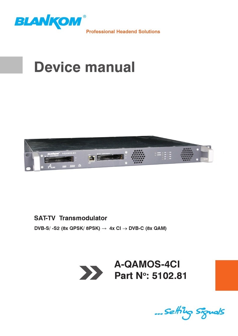
Other Blankom Modulator manuals

Blankom SAT-TV User manual

Blankom

Blankom SAT-TV User manual

Blankom HDC 7016 Instruction Manual

Blankom

Blankom HDC 7016 Instruction Manual

Blankom AMA 299 Application guide

Blankom

Blankom AMA 299 Application guide

Blankom HDC 6012 User manual

Blankom

Blankom HDC 6012 User manual

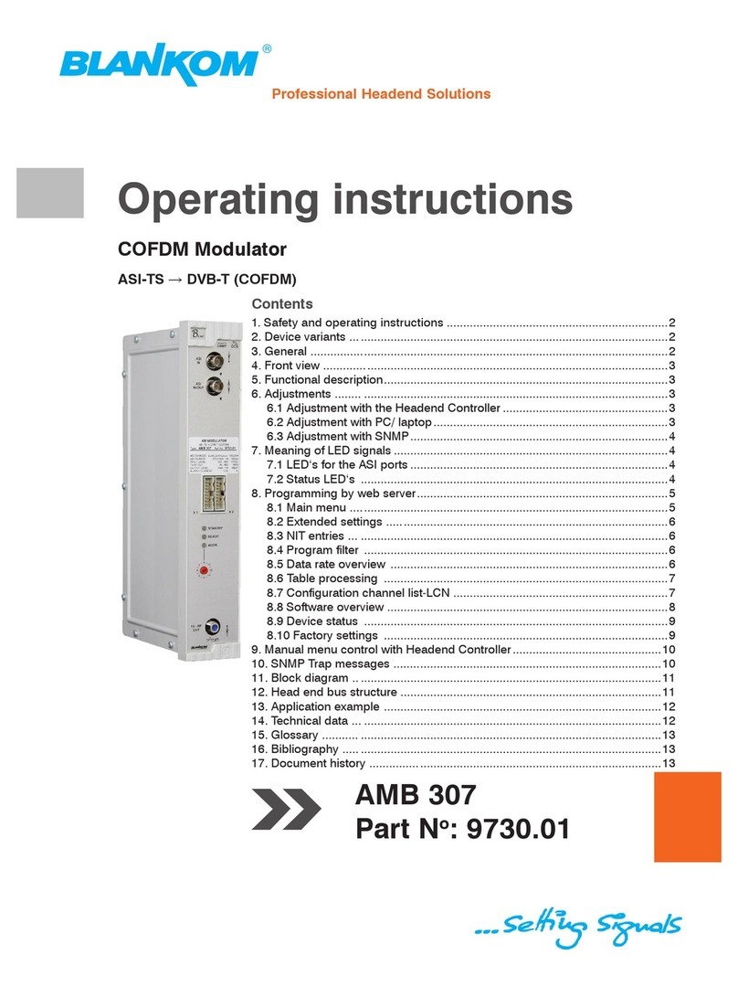
Blankom AMB 307 User manual

Blankom

Blankom AMB 307 User manual

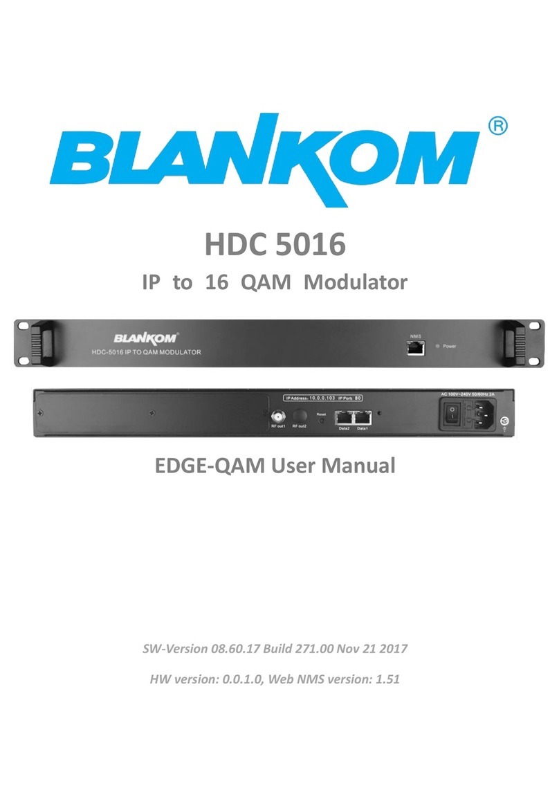
Blankom HDC 5016 User manual

Blankom

Blankom HDC 5016 User manual

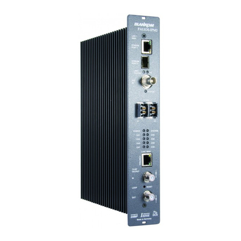
Blankom PALIOS-IPM2 User manual

Blankom

Blankom PALIOS-IPM2 User manual

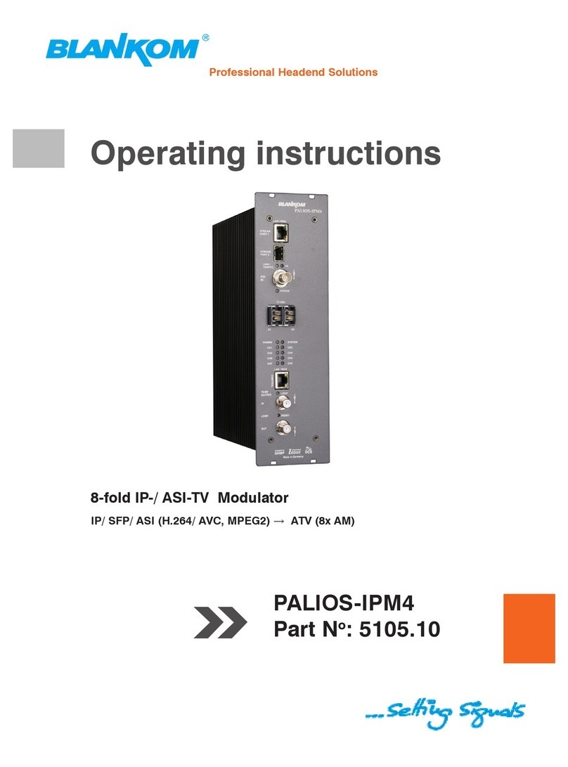
Blankom PALIOS-IPM4 5105.10 User manual

Blankom

Blankom PALIOS-IPM4 5105.10 User manual

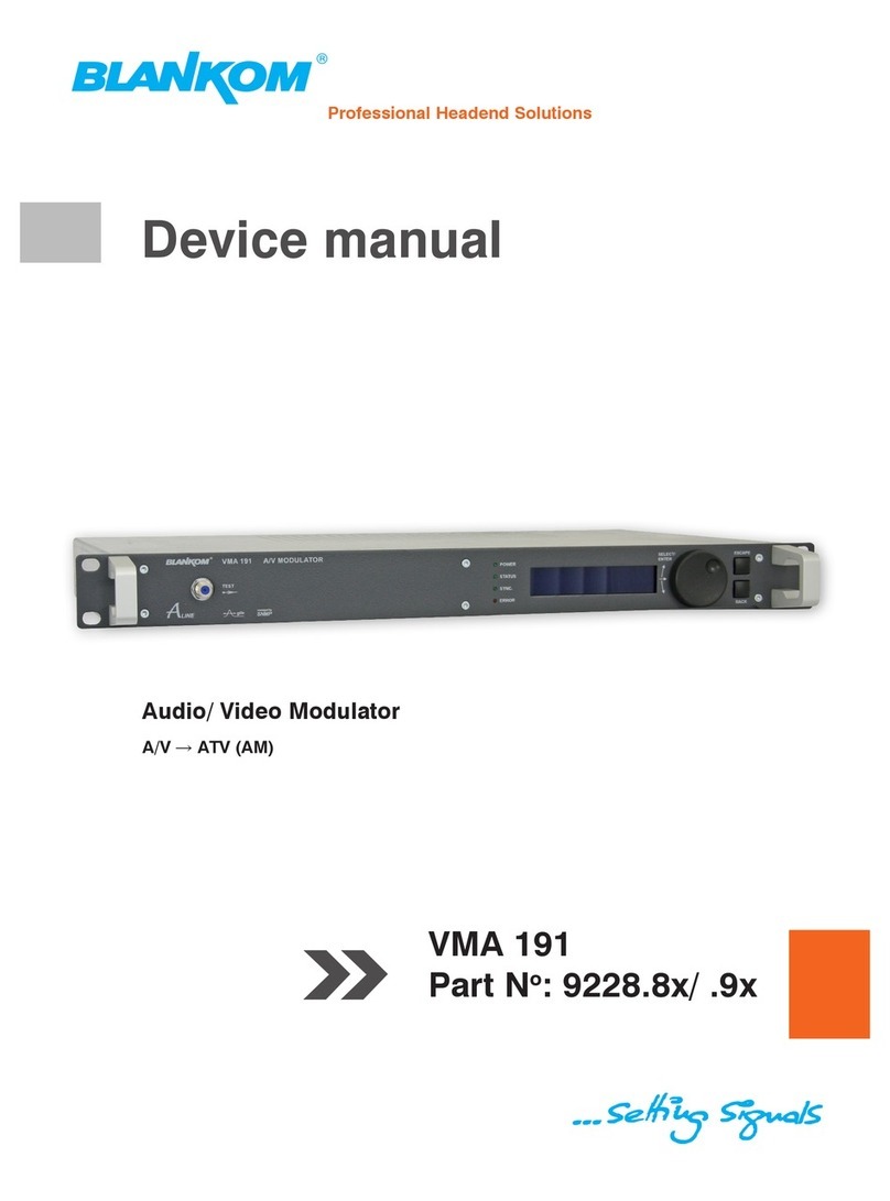
Blankom VMA 191 User manual

Blankom

Blankom VMA 191 User manual

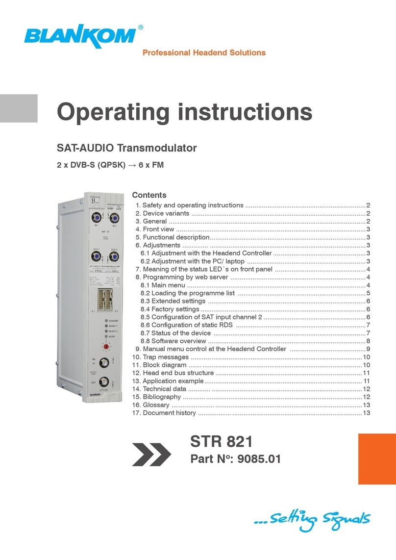
Blankom STR 821 User manual

Blankom

Blankom STR 821 User manual

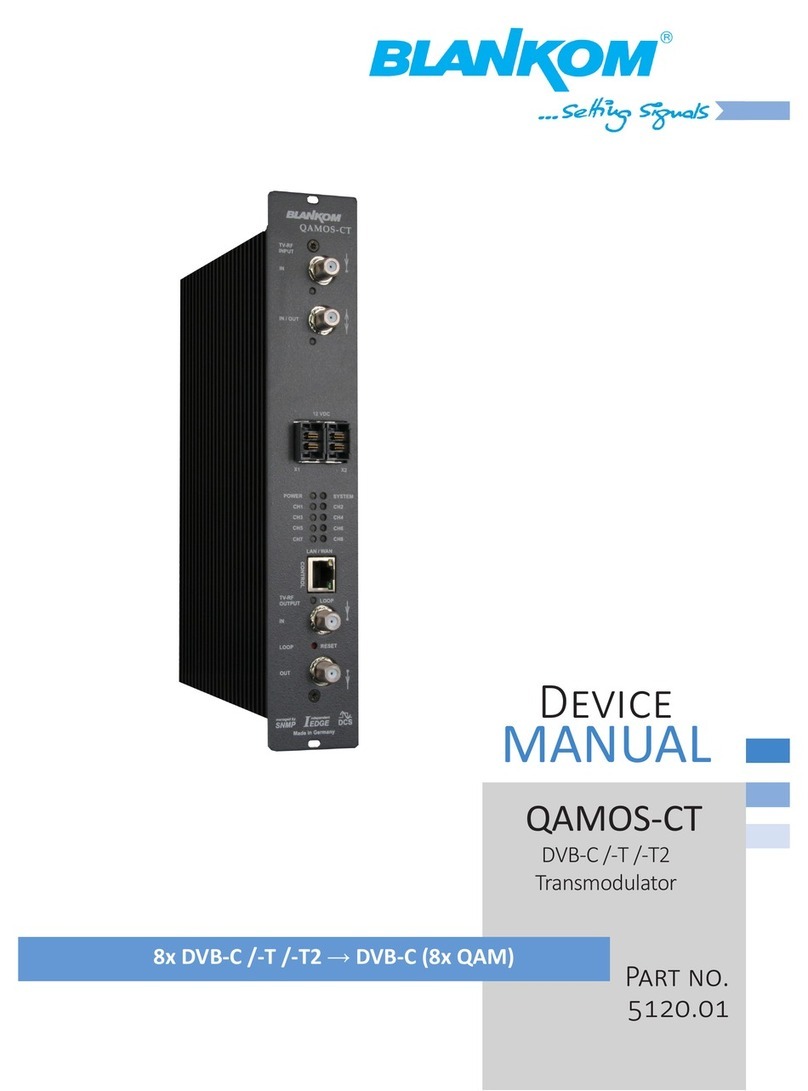
Blankom QAMOS-CT Application guide

Blankom

Blankom QAMOS-CT Application guide

Blankom A-QAMOS-4CI Application guide

Blankom

Blankom A-QAMOS-4CI Application guide

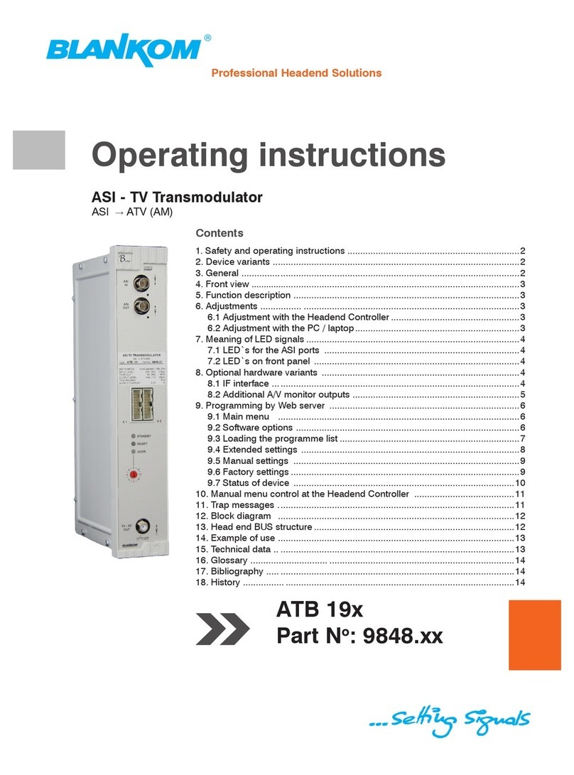
Blankom ATB 19 series User manual

Blankom

Blankom ATB 19 series User manual

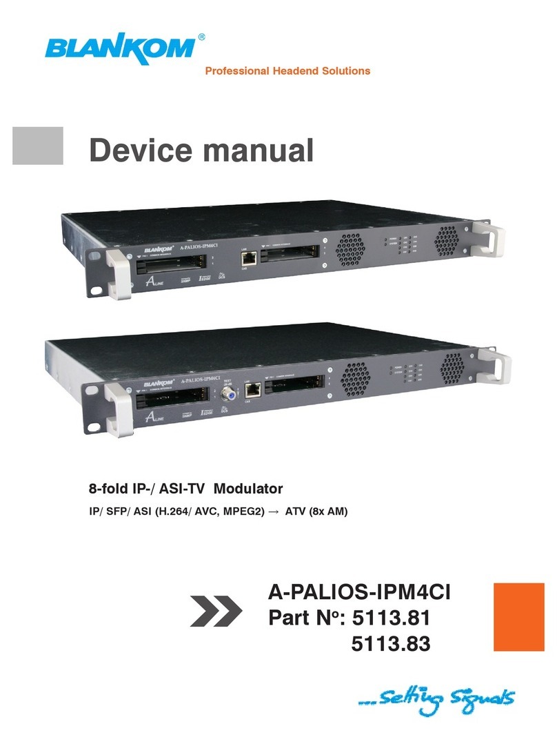
Blankom A-PALIOS-IPM4CI 5113.81 User manual

Blankom

Blankom A-PALIOS-IPM4CI 5113.81 User manual

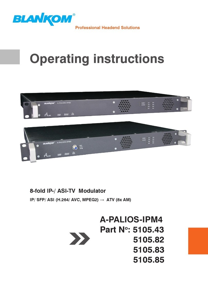
Blankom A-PALIOS-IPM4 User manual

Blankom

Blankom A-PALIOS-IPM4 User manual

Blankom HDC 5016 User manual

Blankom

Blankom HDC 5016 User manual

Blankom HDC 6008CI User manual

Blankom

Blankom HDC 6008CI User manual

Blankom 5105.82 User manual

Blankom

Blankom 5105.82 User manual

Popular Modulator manuals by other brands

Tektronix DS1000 Series user manual

Tektronix

Tektronix DS1000 Series user manual

Ness RL DVB-T Series quick start

Ness

Ness RL DVB-T Series quick start

Questtel B-QAM-HDMI-IP-4CH user manual

Questtel

Questtel B-QAM-HDMI-IP-4CH user manual

axing basic-line Series Operation instructions

axing

axing basic-line Series Operation instructions

Scientific Atlanta Continuum DVP eXtra Dense QAM Array 24 Configuration guide

Scientific Atlanta

Scientific Atlanta Continuum DVP eXtra Dense QAM Array 24 Configuration guide

Radio Shack Video RF Modulator owner's manual

Radio Shack

Radio Shack Video RF Modulator owner's manual

Aiphone KBW-M Specifications

Aiphone

Aiphone KBW-M Specifications

Grundig GSS HDTV Series Assembly instructions

Grundig

Grundig GSS HDTV Series Assembly instructions

Sennheiser SI 30 Instructions for use

Sennheiser

Sennheiser SI 30 Instructions for use

Satlink ST-7632 Series Start guide

Satlink

Satlink ST-7632 Series Start guide

Sencore SMD 989 user manual

Sencore

Sencore SMD 989 user manual

Pico Macom F860 Specifications

Pico Macom

Pico Macom F860 Specifications

Sennheiser SZI 30 General description

Sennheiser

Sennheiser SZI 30 General description

Skywalker SKYMOD1 Installation

Skywalker

Skywalker SKYMOD1 Installation

FTE Maximal SSAV 0269 user manual

FTE Maximal

FTE Maximal SSAV 0269 user manual

ZyCast digi-MOD RL-DM4000D Quick install manual

ZyCast

ZyCast digi-MOD RL-DM4000D Quick install manual

Pico Macom PFAD900CS Specifications

Pico Macom

Pico Macom PFAD900CS Specifications

Multiplex Channel Plus 5214 owner's manual

Multiplex

Multiplex Channel Plus 5214 owner's manual

manuals.online logo
manuals.online logoBrands
  • About & Mission
  • Contact us
  • Privacy Policy
  • Terms and Conditions

Copyright 2025 Manuals.Online. All Rights Reserved.