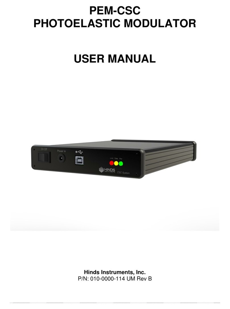
Hinds Instruments PEM-100 User manual

PEM-100
PHOTOELASTIC MODULATOR
USER MANUAL
Hinds Instruments, Inc.
P/N: 010-0000-021 UM Rev H

Copyright © 2006, 2013 by Hinds Instruments, Inc.
THIS DOCUMENT IS PROVIDED “AS IS” WITH NO WARRANTIES
WHATSOEVER, INCLUDING ANY WARRANTY OF MERCHANTABILITY,
FITNESS FOR ANY PARTICULAR PURPOSE, OR ANY WARRANTY OTHERWISE
ARISING OUT OF ANY PROPOSAL, SPECIFICATION OR SAMPLE. All rights
reserved. No part of this publication may be reproduced, stored in a retrieval system,
or transmitted, in any form by any means, electronic, mechanical, by photocopying,
recording, or otherwise, without the prior written permission of Hinds Instruments,
Inc.
Information furnished by Hinds Instruments, Inc. is believed to be accurate and
reliable; however, no responsibility is assumed by Hinds Instruments, Inc. for its use;
nor for any infringements of patents or other rights of third parties which may result
from its use. No license is granted by implication or otherwise under any patent
rights of Hinds Instruments, Inc.
In all respects, the English version of this manual is controlling.
The PEM-100 is covered by the following US patents: (1) 7,800,845, (2) 7,495,205,
(3) 6,970,278, (4) 6,906,844, (5) 6,867,863, (6) 5,886,810, (7) 5,744,721,
(8) 5,652,673.
PEMLabs, Hinds Instruments and the Hinds Instruments, Inc. graphic logo are
trademarks of Hinds Instruments, Inc.
*Third-party brands and names are the property of their respective owners.

CAUTION!
DO NOT turn on your modulator
unless the optical head and the
electronic head are connected by
the head-to-head interconnect
cable.
SERIOUS DAMAGE MAY RESULT!


PEM 100 User Manual v
Table of Contents
Table of Contents..........................................................................................................v
Table of Figures ...........................................................................................................ix
Table of Tables.............................................................................................................xi
Operators’ Safety Summary.........................................................................................1
Terms.....................................................................................................................1
PEM-100 Controller Labels...................................................................................1
AC Power Source..................................................................................................2
Do Not Operate Without Cover.............................................................................2
Unpacking the PEM 100................................................................................................3
Shipping Damage Check......................................................................................3
Unpacking the PEM Optical Head........................................................................4
Special Instructions for I/FS50 Optical Head.......................................................................4
Special Instructions for II/FS42 & II/IS42 Optical Head.......................................................6
1 Introduction..............................................................................................................11
Overview..............................................................................................................11
PEM-100 Controller Accessories .......................................................................12
Rack Mounting Kit .............................................................................................................12
RS232 Converters.............................................................................................................12
2 PEM-100 Controller..................................................................................................13
PEM-100 Controller Front Panel.........................................................................13
PEM-100 Controller Front Panel Buttons..........................................................................14
PEM-100 Controller Rear Panel..........................................................................15
PEM-100 Controller Rear Panel Connections...................................................................15
3 Modulator Head Assembly ......................................................................................17
Optical Head........................................................................................................17
Electronic Head...................................................................................................20
4 Initial Set-Up.............................................................................................................21
Connecting the PEM Optical and Electronic Heads..........................................21
Optical Bench Set-up..........................................................................................25
Functional Check...............................................................................................................25
5 PEM-100 Controller Display.....................................................................................27
Display Modes.....................................................................................................27
Local Control Mode ...........................................................................................................27
Voltage Control Mode........................................................................................................28
Remote Control Mode .......................................................................................................29
User Presets........................................................................................................30
Local Control Presets ........................................................................................................30
Voltage Control Presets.....................................................................................................31
System Configuration.........................................................................................32
Screen Settings .................................................................................................................32
Restore Defaults................................................................................................................32
RS232 Settings..................................................................................................................33
System Info........................................................................................................................33
6 Operating the PEM-100 Controller ..........................................................................35
Front Panel Operation.........................................................................................35
Power Up...........................................................................................................................35

Table Of Contents
vi PEM 100 User Manual
Factory Default Parameters..............................................................................................36
Setting Front Panel Parameters........................................................................................36
Setting Wavelength...........................................................................................................36
Setting Retardation ...........................................................................................................37
Setting the Frequency.......................................................................................................37
Setting VControl................................................................................................................37
Selecting Factory Default Presets.....................................................................................38
Saving User Defined Presets............................................................................................38
Resetting the Controller to Default Parameters................................................................38
Local Control Mode Factory Defaults................................................................................39
Voltage Control Mode Factory Defaults............................................................................39
7 PEM Control Software .............................................................................................41
Installing the PEM Control Software..................................................................41
Setup of PEM-100 Controller for use with PEM Control Software...................41
Launching the PEM Control Software and verifying communication with the PEM-
100 Controller......................................................................................................42
Choosing the Proper Headset Type...................................................................42
Operating the PEM Control Software ................................................................43
Main Display Screen.........................................................................................................44
V Control Operation ..........................................................................................................47
8 Command Line Interpreter (CLI) .............................................................................49
Example Setup of PEM-100 Controller for use with the CLI.............................49
PEM-100 ‘Command Line Interpreter (CLI)’ Command Descriptions...............................51
9 Troubleshooting.......................................................................................................53
Troubleshooting Guide – Symptoms & Possible Remedies............................53
Over Limit Conditions in Local Control & Voltage Control Modes..................55
10 Maintenance...........................................................................................................57
Calibration...........................................................................................................57
Adjustment of Peak Retardation Calibration.....................................................................57
Maintenance........................................................................................................57
Power Line Fuse Replacement.........................................................................................58
Cleaning ..............................................................................................................59
Recommended Optics Cleaning Solutions .......................................................................59
Cleaning the Optics...........................................................................................................60
Cleaning the Controller .....................................................................................................61
A Calibration................................................................................................................63
PEM 100 Calibration ...........................................................................................63
Calibration Theory ..............................................................................................64
Light Sources for Modulator Calibration...........................................................65
Calibration Using an Oscilloscope....................................................................66
Multiple Reflection Techniques .........................................................................69
Static Waveplate Techniques.............................................................................69
Bessel Function Zero Methods..........................................................................70
Bessel Function Ratio Methods.........................................................................71
Parallel Polarizer Calibration at a Single Wavelength......................................72
B Specifications..........................................................................................................77
General- Controller .............................................................................................77
Displayed Parameter Specifications..................................................................77
Input / Output Specifications .............................................................................78
Environmental.....................................................................................................78
Approvals............................................................................................................78

Table Of Contents
PEM 100 User Manual vii
EMC & Safety Standards ....................................................................................78
C Optical Head Specifications....................................................................................79
Advanced Thermal Control (ATC) Option Specifications:................................79
D User Support Information .......................................................................................81
PEM 100 Limited Warranty .................................................................................81
Exclusions..........................................................................................................................81
Overview of the PEM 100 Help System..............................................................82
Return For Repair Procedure.............................................................................83
Packaging..........................................................................................................................83
Items To Include................................................................................................................83
Shipping Arrangements.....................................................................................................83
Return Shipping Address...................................................................................................84
Shipping Costs ..................................................................................................................84
Index ............................................................................................................................85

Table Of Contents
viii PEM 100 User Manual

PEM 100 User Manual ix
Table of Figures
Figure S.1 Compliance Labeling...................................................................................... 1
Figure S.1 I/FS50 Remove Shipping Disk......................................................................... 4
Figure S.2 I/FS50 Remove Blue Foam Disk..................................................................... 5
Figure S.3 I/FS50 Remove Inner Blue Foam & Lens Tissue........................................... 5
Figure S.4 II/FS42 Remove Shipping Disk & Lid ............................................................. 6
Figure S.5 II/FS42 Remove Unpacking Instructions ....................................................... 7
Figure S.6 II/FS42 Remove Blue Foam & Yellow Clips ................................................... 7
Figure S.7 Junction between Optical Element and Transducer..................................... 8
Figure S.8 Removing Yellow Transducer Support Clips................................................ 8
Figure 1.1 PEM 100 Photoelastic Modulator...................................................................11
Figure 2.1 PEM-100 Front Panel OFF State ....................................................................13
Figure 2.2 PEM-100 Rear Panel.......................................................................................15
Figure 2.3 RS232 Connections........................................................................................16
Figure 3.1 Model I/FS50 Optical Head Dimensions........................................................17
Figure 3.2 Model II/FS42 Optical Head Dimensions.......................................................18
Figure 3.3 Model II/ZS50 Optical Head Dimensions.......................................................18
Figure 3.4 II/FS84 Optical Head Dimensions..................................................................19
Figure 3.5 II/ZS37 Optical Head Dimensions..................................................................19
Figure 3.6 Electronic Head Dimensions .........................................................................20
Figure 4.1 Connecting I/FS50 Optical Head to Electronic Head....................................22
Figure 4.2 Connecting II/ZS50 Optical Head to Electronic Head...................................22
Figure 4.3 Connecting II/ZS50 Optical Head to Electronic Head (Cross Connection).23
Figure 4.4 Connecting 1/FS50 Optical Head with ATC Option to Electronic Head......24
Figure 4.5 Block Diagram for Oscilloscope Calibration Method...................................25
Figure 4.6 Oscilloscope Waveform for PEM Set to 0.25 Wave Retardation Between
Crossed Polarizers and PEM 1f Reference Signal ..................................................26
Figure 5.1 Local Control Mode Display............................................................................27
Figure 5.2 Voltage Control Mode Display.......................................................................28
Figure 5.3 Remote Control Mode Display.......................................................................29
Figure 5.4 Local Control Mode – User Presets Menu ....................................................30
Figure 5.5 Voltage Control Mode – User Presets............................................................31
Figure 5.6 System Configuration Menu..........................................................................32

Table of Figures
x PEM-100 User Manual
Figure 6.1 PEM-100 Controller Front Panel....................................................................35
Figure 7.1 Head type selections......................................................................................43
Figure 7.2 Main Display Screen.......................................................................................44
Figure 7.3 Advanced Setting Dialog Box........................................................................46
Figure 7.4 V Control Mode Dialog Box ...........................................................................47
Figure 9.1 Display – No Connection between Head-Set & Controller...........................54
Figure 9.2 Display - Retardation Over Limit Message ...................................................55
Figure 9.3 Display - Voltage Over Limit Message..........................................................55
Figure 10.1 Opening the Power Fuse Holder .................................................................58
Figure 10.2 Fuses Properly Inserted In Fuse Holder.....................................................59
Figure 10.3 Direction of cotton swab wiping motion.....................................................60
Figure 10.4 Junction between Optical Element and Transducer..................................61
Figure A.1 Typical Optical Setup ....................................................................................64
Figure A.2 Oscilloscope Calibration Method .................................................................66
Figure A.3 Waveform for Half-wave Retardation............................................................67
Figure A.4 Retardation 90% of Half-wave.......................................................................67
Figure A.5 Retardation 110% of Half-wave.....................................................................68
Figure A.6 Waveform for a Retardation of Four Half-waves..........................................68
Figure A.7 Setup for Double Pass Modulation...............................................................69
Figure A.8 Determining the Controller Settings for which J0= 0 .................................70
Figure A.9 Ratio V2f/VDC vs retardation, radians............................................................73
Figure A.10 Ratio V2f/VDC vs. retardation (radians) for parallel polarizers...................74

PEM 100 User Manual xi
Table of Tables
Table 5.1 PEM-100 Controller RS232 Settings ................................................................33
Table 5.2 PEM-100 Controller Calibration & SW Suffix..................................................33
Table 6.1 Local Control Mode Factory Defaults.............................................................39
Table 6.2 Voltage Control Mode Factory Defaults..........................................................39
Table 8.1 CLI Port Settings & ASCII Setup .....................................................................49
Table 8.2a PEM-100 Command Line Interpreter Command Descriptions ....................51
Table 8.2b PEM-100 Command Line Interpreter Command Descriptions....................52
Table 9.1a Troubleshooting Guide – Symptoms & Possible Remedies .......................53
Table 9.1b Troubleshooting Guide – Symptoms & Possible Remedies.......................54
Table D.1 Contacting Technical Support........................................................................82

Table of Tables
xii PEM-100 User Manual

PEM 100 User Manual 1
Operators’ Safety Summary
The general safety information in this summary is for operators of the PEM 100
Photoelastic Modulator System. Specific warnings and cautions may be found
throughout the manual where they apply, but may not appear in this summary.
Terms
WARNING statements identify conditions or practices that could result in personal
injury or loss of life.
CAUTION statements identify conditions or practices that could result in damage to
the equipment or other property.
NOTICE statements identify conditions or practices that are important in proper use
of the equipment to get the expected results.
PEM-100 Controller Labels
The serial number and CE certification labels are located at the lower right corner on
the PEM-100 Controller rear panel as shown in figure S.1 below.
Figure S.1 Compliance Labeling

Operators’ Safety Summary
2 PEM 100 User Manual
AC Power Source
This product is intended to operate from an AC power source in the 100-240 VAC
range, 50-60 Hz, line to neutral. A protective ground connection by way of the
grounding connector in the power cord is essential for safe operation.Power line
requirements are listed in the specifications section and on the rear panel of the
instrument.
The power cord provided with this instrument is less than 3 meters in length.
Use only the power cord and connector specified for your product to work with your
local power outlets. Use only a power cord that is in good condition.
The appliance inlet or plug on cord should always be positioned to be accessible by
the operator. To disconnect all power from the instrument, pull the power cord from
the wall outlet or from the appliance inlet.
Do Not Operate Without Cover
To avoid personal injury, do not operate the PEM-100 Controller without the cover.
Ensure the controller ventilation openings located on the top and bottom of the
enclosure are clear of any obstructions.

PEM 100 User Manual 3
Unpacking the PEM 100
Shipping Damage Check
Inspect all system components for obvious shipping damage. The PEM 100 is a
precision instrument that can be damaged by rough handling. Your unit was
packaged to minimize the possibility of damage in transit. Therefore, we
recommend that you save the specially designed shipping container for any future
shipment of your modulator unit. In particular, we recommend you save the internal
packing materials for the optical head.
In the event your order arrives in damaged condition, it is important that the following
steps be taken immediately. The title transfers automatically to you, the customer,
once the material is entrusted to the transport company.
1. DO NOT RETURN THE INSTRUMENT TO HINDS INSTRUMENTS, INC. until
the following steps are completed. Failure to follow this request will jeopardize
your claim with the insurance company.
2. If a “Shock Watch” is present on the outer shipping container or anywhere inside,
note the location and the condition of the shock watch. If the shipment receives
handling rough enough to trigger the shock watch, the watch will turn red.
3. Open the container and inspect the contents. Do not throw away the container or
any damaged parts. Try to keep all items in the same condition as originally
received.
4. Notify the Transport Company immediately in writing, preferably by facsimile or
email, about the shipping damage.
5. Wait for the transport company’s representative to inspect the shipment
personally.
6. After inspection, request Hinds Instruments’ permission to return the damaged
instrument by calling the service department at (503) 690-2000 or email to
service@hindsinstruments.com. A return authorization number (RMA) will be
assigned to you.See Overview of the PEM 100 Help System on page 82 for
further contact information.
7. Return approved items to Hinds Instruments Inc. at the following address:
Hinds Instruments, Inc.
7245 NW Evergreen Pkwy
Hillsboro, OR 97124-5850
8. After return permission is given and we receive the instrument, an estimate of the
cost of repair will be sent to you in the event you choose to submit a claim to the
transport company.

Unpacking the PEM-100
4 PEM 100 User Manual
Unpacking the PEM Optical Head
CAUTION
PLEASE USE CARE when unpacking the PEM optical head, for
this assembly is very fragile. Please follow the unpacking
instructions carefully. Unless this is done, the PEM system will
not operate and the optical head may be irreversibly damaged.
Special Instructions for I/FS50 Optical Head
The following unpacking instructions are for an I/FS50 PEM optical head.
All optical head models except for the II/FS42 and II/IS42 follow these instructions.
1. Ensure the work surface is clean and free of dust.
2. Using a #1 Phillips screw driver, remove the shipping disk.
Figure S.1 I/FS50 Remove Shipping Disk

Unpacking the PEM Optical Head
PEM 100 User Manual 5
3. Remove the blue foam disk.
Blue foam disk
Figure S.2 I/FS50 Remove Blue Foam Disk
4. Carefully remove the inner blue foam and lens tissue from this side of the optics,
thus exposing the PEM optics.
Inner Foam & Lens Tissue
Figure S.3 I/FS50 Remove Inner Blue Foam & Lens Tissue
NOTE: Also remove the shipping disk and inner blue foam on the
opposite side of the PEM.
5. Repeat steps 1 through 4 for the opposite side of the PEM.

Unpacking the PEM-100
6 PEM 100 User Manual
6. Blow air on the optics to ensure there is no lint or dust particles on the optic
surfaces.
CAUTION
Use only oil free air when blowing lint or dust particles from the
optic surfaces. If using canned air, hold the container upright or
liquid will spray onto the optic surface.
7. Save shipping disk, packing foam and lens tissue in the zip lock bag provided in
the event that the PEM is returned to Hinds.
The shipper assumes all freight damage risk if the optical head is not
packaged as supplied.
Special Instructions for II/FS42 & II/IS42 Optical Head
The following unpacking instructions are for an II/FS42 and II/IS42 PEM optical
heads. Unpacking other optical head designs may vary slightly.
1. Ensure the work surface is clean and free of dust.
2. Using a #1 Phillips screw driver, remove the Shipping disk and lid.
Figure S.4 II/FS42 Remove Shipping Disk & Lid
3. Remove the shipping disk and unpacking instructions.

Unpacking the PEM Optical Head
PEM 100 User Manual 7
Figure S.5 II/FS42 Remove Unpacking Instructions
4. Remove the blue foam and lens tissue.
NOTE: The foam on the other side of the optics will be removed
through the shipping disk on the opposite side of the PEM.
Blue Foam Qty 2 Yellow Rubber Clips
Figure S.6 II/FS42 Remove Blue Foam & Yellow Clips
5. Remove the yellow transducer support clips (i.e. for models II/FS42 and II/IS42).
See Figure S.7 on the following page.

Unpacking the PEM-100
8 PEM 100 User Manual
CAUTION
Be very careful to protect the optic and transducer bond. Do not
apply excessive force to this bonded junction when removing
the yellow packing supports.
TransducerOptical Element Junction
Figure S.7 Junction between Optical Element and Transducer
6. Carefully hold the gold plated transducer in place with the thumb and forefinger
and gently grasp the top center flap of the first packing support. Slightly bend
this flap back and rotate the clip forward while lifting out the support clip. Repeat
this process for the second yellow packing support.
Transducer
Yellow Clip (Qty 2)
Figure S.8 Removing Yellow Transducer Support Clips
7. Replace the lid and tighten all screws until snug.
Table of contents
Other Hinds Instruments Modulator manuals
Popular Modulator manuals by other brands
PROception
PROception proMOD1 Mk2 Installation and operation instructions
Net Media
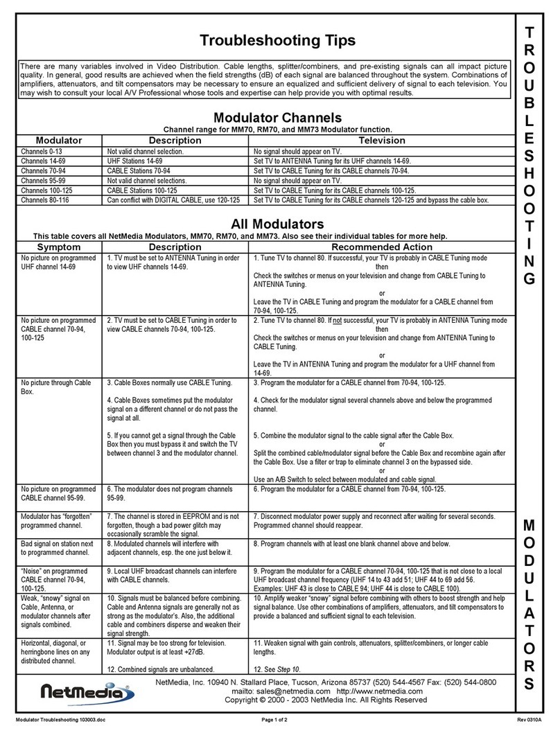
Net Media TriplePlay MM73 Troubleshooting tips
Channel Plus
Channel Plus 5515 installation manual

Net Media
Net Media RM70 Specifications

Pro2
Pro2 Pro2 RFD-2169BF manual
Net Media
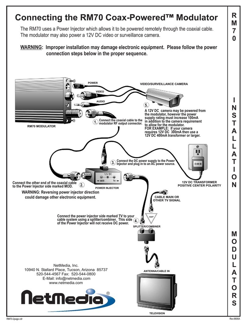
Net Media RM70 installation instructions
