Del ozone Big Dipper EC-AG1U User manual

EC–AG1U, EC–AG2U
Installation & Operations Manual
4-2353-01 Rev.A


TABLE OF CONTENTS
SECTION 1 General Information
1A. Description ........................................................................................ 1
1B. Specifications.................................................................................... 1
1C. Warranty Summary ........................................................................... 1
SECTION 2 Installation
2A. Location............................................................................................. 1
2B. Wall Mounting ................................................................................... 2
2C. Electrical ........................................................................................... 2
2D. Plumbing........................................................................................... 2
SECTION 3 Operation
3A. General ............................................................................................. 3
3B. Initial System Start-Up ...................................................................... 5
3C. System Shut-Down ........................................................................... 5
SECTION 4 Maintenance & Service
4A. System Electromechanical Overview................................................ 5
4B. System Maintenance......................................................................... 5
4C. Ozone Generator Servicing .............................................................. 6
4D. Troubleshooting ................................................................................ 8
Warranty ................................................................................................ 10

IMPORTANT SAFETY INSTRUCTIONS
READ AND FOLLOW ALL INSTRUCTIONS.
• Read this manual completely before attempting installation.
• All permanent electrical connections should be made by a qualified
electrician.
• Connect to a grounding type receptacle only. If the ozone generator
electrical connection is to be attached to the pool controls, be sure
the pool controls are protected by a Ground Fault Circuit Interrupter
(G.F.C.I.). If the ozone generator is connected to an independent
electrical supply, then a G.F.C.I. must be installed between the ozone
generator and the electrical supply.
• Do not bury cord.
• Warning – To reduce the risk of electrical shock, replace damaged cord
immediately.
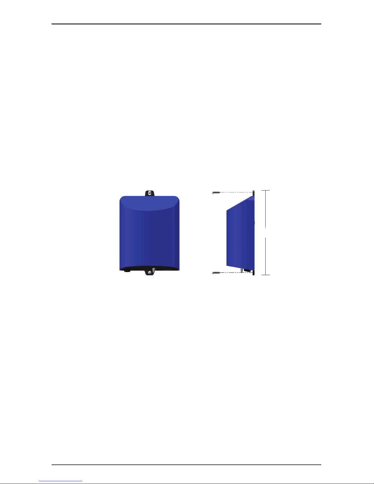
• Install at least 5 feet (1.5 meters) from wall of pool. Install ozone
generator no less than one (1) foot above maximum water level to
prevent water from contacting electrical equipment. Install in
accordance with the installation instructions.
• Follow all applicable electrical codes.
• Electric shock hazard. Be sure to turn power OFF and disconnect from
power source before any service work is performed. Failure to do so
could result in serious injury or death.
• The ozone generator must be installed in an outdoor location,
or indoors in a forced air ventilated room, and installed so that the
orientation is exactly as shown in Figure 1.
• Mount the ozone generator so that it is inaccessible to anyone in the
pool. Never attempt any servicing while unit is wet.
• Plastic ozone supply tubing is supplied with the ozone generator.
Never replace this tubing with metal tubing.
• Warning – Short-term inhalation of high concentrations of ozone and
long term inhalation of low concentrations of ozone can cause serious
harmful physiological effects. DO NOT inhale ozone gas produced by
this device.
• For your safety, do not store or use gasoline, chemicals or other
flammable liquids or vapors near this or any other appliance.
SAVE THESE INSTRUCTIONS!
EC–AG1U, EC–AG2U

1
EC–AG Installation & Operations Manual
SECTION 1 General Information
1A. Description
The EC–AG Ozone Generators described in this manual
are designed to provide the benefits of ozonated water in an
environmentally safe and effective manner. The high quality,
specially engineered components ensure efficient ozone output
and reliable performance. As a result of proper use of the Ozone
Generators, unpleasant effects of traditional chemical use are
virtually eliminated. The Ozone Generators are safe and harmless
to your equipment when installed properly.
1B. Specifications
Flow rate: 15 scfh (nominal)
Flow rate and ozone output will vary with installation.
Power Requirements:
• EC–AG1U: 120-240V, 50-60 Hz, 1Ø, 0.10 Amp Max
• EC–AG2U: 120-240V, 50-60 Hz, 1Ø, 0.05 Amp Max
Shipping Weight:
• EC–AG1U: Approx. 1.8 pounds / 0.8 kg
• EC–AG2U: Approx. 1.6 pounds / 0.7 kg
Location Requirements:
• Mounting: Wall mount in a clean, protected area.
• Ambient Temp: 30°F - 120°F (0°C - 50°C)
1C. Warranty Summary
Limited Warranty: 1 year warranty on entire generator.
See Warranty section for limitations and details on obtaining
warranty service.
SECTION 2 Installation
2A. Location
The Ozone Generator units are designed for wall mounting. See
Figure 1. Mount in a clean, protected area, either indoors or
outdoors (preferably out of direct sunlight). Locate out of reach

2
EC–AG Installation & Operations Manual
of sprinklers or drainage spouts. Allow sufficient access for
maintenance and all tubing and electrical wires. Ozone Generator
should be installed at least (not less than) one foot above the
maximum water level. See Section 2D-2, Ozone Gas Line, for
plumbing instructions based on mounting location.
2B. Wall Mounting
a. Refer to Figure 1 to mark the locations for the two mounting
screws.
b. Install screws (or other hardware appropriate for mounting
surface) through the two mounting holes built in to the base of
the EC–AG ozone system.
2C. Electrical
2C-1. Main Power
Connect the Ozone Generator to the pool timing clock so that the
Ozone Generator operates simultaneously with the pool pump. The
circuit must be protected by a ground-fault circuit interrupter (GFCI)
installed in accordance to electrical code. Refer to the IMPORTANT
SAFETY INSTRUCTIONS at the beginning of this manual for
important wiring information. If the EC–AG power cord comes with
a built-in receptacle and the pump is equipped with a standard plug
(NEMA 5-15P), the pump may be plugged in on top of the EC–AG
cord (pump current must not exceed 15A). Plug must be protected
from moisture.
2D. Plumbing
Ozone gas is introduced to the pool circulation line using a venturi
Injector. Suction developed by the venturi allows the Ozone
Figure 1: Wall Mount
8.0"

3
EC–AG Installation & Operations Manual
Generator to operate safely under vacuum. Note: The Injector
needs to be installed after all other equipment or possible failure
may occur.
2D-1. Plumbing the Above Ground Injector Assembly
Note: Figure 2 and the instructions below describe Injector
installation immediately after the Filter. For pools equipped with a
heater, the Injector must be installed AFTER the heater. The fittings
provided may be used to connect the Injector directly to the wall of
the pool or the outlet of the heater.
a. Wrap Teflon tape on all male pipe threads.
b. Disconnect the pool’s return hose from the Filter. Keep the hose
elevated to aviod draining the pool.
c. Use either the straight or elbow fittings provided to connect the
Injector to the discharge port of the Filter. Ensure that the flow
arrow on the Injector is pointed in the direction of water flow, and
that the Ozone Port is accessible.
d. Reconnect the pool’s return hose to the outlet of the injector.
e. Attach Hose Barb Fitting to the Ozone Port on the Injector.
2D-2. Ozone Gas Line
Connect the end of the Ozone Supply Tubing that is closest to the
Check Valve to the Hose Barb Fitting on the Injector. Secure with a
supplied hose clamp. If the Ozone Generator is mounted above the
water line attach the other end of the Ozone Supply Tubing to the
ozone out fitting on the EC–AG and secure with the supplied hose
clamps. If the Ozone Generator is mounted below the water
line, the Ozone Supply Tubing must be run to a point above the
water line. Simply coil the tubing into a complete circle about 6˝
diameter and fasten it above the water line. This will act as a water
trap to prevent water from running back to the Ozone Generator.
SECTION 3 Operation
3A. General
To achieve optimal performance from the Ozone Generator, the pool
must be as clean as possible to start with.
a. Backwash or clean filters one day before starting the Ozone
Generator.
b. Superchlorinate pool water using a chlorine based shock
treatment.

4
EC–AG Installation & Operations Manual
Figure 2: Typical Injector Installation (Pool without heater)
EC–AG
Ozone Generator Ozone
Supply Tubing
Check Valve
Hose Barb Fitting Injector
Filter
Return to Pool
From Pool
Pool Pump

5
EC–AG Installation & Operations Manual
c. Test pool chemistry and adjust pH between 7.4 and 7.6. Adjust
total alkalinity between 80 and 120 ppm.
d. Run pool filtration continuously for 24 hours prior to starting
Ozone Generator.
3B. Initial System Start-Up
a. Turn on pool circulation system.
b. Check for leaks.
c. Verify that ozone is being pulled into the Injector by checking for
bubbles at the return.
If you experience complications, see TROUBLESHOOTING Section
4D, call (800) 676-1335 or visit www.delozone.com for assistance.
3C. System Shut-Down
If the system is to be shut down for an extended period disconnect
the Ozone Generator power cord and disconnect the Ozone Supply
Tubing from the Ozone Generator.
SECTION 4 Maintenance and Service
4A. System Electromechanical Overview
4A-1. Internal Components:
Ozone Module: Each Ozone Module consists of a Power Supply
connected by two high voltage wires to an Ozone Cell.
4B. System Maintenance
4B-1. Ordering Information
To locate a dealer nearest you call 1.800.676.1335 ext. 249 or visit
our web site www.delozone.com
Be prepared with the following information:
• Name • Address • Model # • Date Purchased
4B-2. Standard Replacement Parts List
a. EC–AG1U Ozone Module 9-1292-01
b. EC–AG2U Ozone Module Assembly 9-1293-01
c. Check Valve and Ozone Supply Tubing Assembly 9-0777-01
Item (c.) must be replaced once a year.

6
EC–AG Installation & Operations Manual
4B-3. Ozone Module performance will degrade over time. Replace
the Ozone Module after 15,000 hours of operation. (15,000 hours
equals approximately 5 years for a pool system that operates 8
hours/day, every day.) See Section 4C for module replacement
instructions.
4B-4. While operating, check regularly to see if bubbles are
entering the pool. (If you have installed an MDV, check the MDV for
bubbles.)
4B-5. Regularly inspect Ozone Supply Tubing for cracks or wear.
Also check to make sure no water is present between the Check
Valve and the Ozone Generator. This indicates Check Valve failure
and the Check Valve and Ozone Supply Tubing Assembly should be
replaced. (replacement part number 9-0777-01) immediately.**
**WARNING: Trace amounts of nitric acid may be present in
the check valve or tubing and could be mildly corrosive. If
condensation is present, shut off Ozone Generator and allow
the moisture to be drawn out or dried up prior to servicing.
4C. Ozone Generator Servicing
4C-1. The Ozone Generator must be removed from the wall before
servicing. To remove the Ozone Generator:
a. Disconnect service to Ozone Generator.
b. Disconnect the power cord from the pool timer circuit.
c. Disconnect the Ozone Supply Tubing from the bottom of the
Ozone Generator.
d. Remove the two wall mounting screws.
4C-2. Opening the Ozone Generator
The Ozone Generator enclosure consists of two plastic parts that
clip together. They are held in place by one screw. To open the
enclosure:
a. Remove the Cover Screw on the back side of the base of the
EC–AG (Figure 3).

7
EC–AG Installation & Operations Manual
b. Using a flat head screwdriver or fingers, pry the two Cover Tabs
outward to release the cover from the base.
c. Lift the cover up (Figure 4).
d. Slide the cover forward and off.
Figure 3: Cover Screw and Tabs
Figure 4: Lifting Cover
Figure 5: Sliding Cover Off
LIFT COVER UP
SLIDE COVER
OFF

8
EC–AG Installation & Operations Manual
4C-3. Ozone Module Replacement
a. Open the Ozone Generator as described in section 4C-2.
b. Remove the Mounting Hardware.
c. Disconnect power supply connector (red & black wires).
d. Lift Ozone Cells, Grommet, Hose Barb Fitting, and Ozone Tubing
up and out from the Base Plate.
e. Remove and discard Ozone Cell, Power Supply, Hose Barb
Fitting, and Ozone Tubing.
f. Place new Grommet into enclosure wall.
g. Insert new Hose Barb Fitting making sure to align the Hose Barb
Fitting correctly and insert it completely into Grommet.
h. Install Power Supply with Mounting Hardware Route Power
Supply wires to the left side of the Base Plate.
i. Connect Power Supply connectors to wire harness.
j. Slide cover into position while lifting the base of the cover up.
k. Lower cover over Ozone Cell and snap Cover Tabs into place.
l. Replace Cover Screw.
m.Reinstall the EC–AG in to the pool, reconnect Ozone Supply
Tubing to Hose Barb Fitting and reconnect the power cord.
4D. Troubleshooting
Knowledge of electrical applications is required for trouble shooting.
Contact a certified electrician if you are unsure of your ability to
service the equipment. Improper servicing will void the Warranty.
Figure 6: Internal Component Locations
POWER SUPPLY
MOUNTING HARDWARE
OZONE CELL
HOUSE BARB FITTING
BASE PLATE
OZONE TUBING
GROMMET

9
EC–AG Installation & Operations Manual
Symptom: No Flow.
1. Injector not supplying adequate suction.
a. Check pump and ensure water is flowing through Injector.
b. Check that pump skimmer and filter are clean.
c. Check that Injector is plumbed in the right direction.
d. Ensure that there is no debris clogged inside the Injector.
2. Ozone Supply Tubing is impaired.
a. Check for kinks or clogs.
b. Check for cracks or cuts.
c. Check connections.
d. Check that the Check Valve is installed with the arrow pointing
towards the Injector.
e. Be sure that the Check Valve has not become fouled with
debris. Disconnect the Ozone Supply Tubing from the Injector.
With the pump running, test the end of the Hose Barb Fitting
with your thumb, and feel for suction. Wash your hands
immediately afterwards to remove any residual nitric acid. If
there is sufficient suction without the Check Valve, replace the
Check Valve and Ozone Supply Tubing.
Symptom: Ozone Supply Tubing becomes yellow/brown and brittle.
1. The high concentration of ozone created by the advanced
plasma gap ozone generators, as well as environmental
conditions like UV sunlight will tend to deteriorate the supplied
ozone tubing. This is normal and acceptable, as long as the
tubing doesn’t become cracked and leak. Because of this, DEL
recommends replacing the Ozone Supply Tubing and your Check
Valve every year.

10
EC–AG Installation & Operations Manual
DEL OZONE
LIMITED ONE YEAR WARRANTY
The limited warranty set forth below applies to products manufactured by DEL OZONE – 3580 Sueldo Street, San Luis
Obispo, California 93401, and sold by DEL OZONE or its authorized dealers. This limited warranty is given only to the first
retail purchaser of such products and is not transferable to any subsequent owners or purchasers of such products.
DEL Ozone warrants that it or its authorized dealers will repair or replace, at its option, any part of such products proven
to be defective in materials or workmanship within ONE (1) year from the date of retail purchase of such products. (All
parts) ANY REPAIR OR REPLACEMENT WILL BE WARRANTED ONLY FOR THE BALANCE OF THE ORIGINAL
WARRANTY PERIOD OR NINETY (90) DAYS, Whichever is greater.
NOTE: USE ONLY DEL AUTHORIZED DEL REPLACEMENT PARTS. USE OF ANY OTHER PART(S) WILL VOID
THIS WARRANTY.
Any replaced parts must be returned to DEL OZONE for warranty evaluation.
THIS LIMITED WARRANTY DOES NOT INCLUDE ANY OF THE FOLLOWING:
(a) Any labor charges for troubleshooting, removal, or installation of such parts.
(b) Any repair or replacement of such parts necessitated by faulty installation, improper maintenance, improper
operation, misuse, abuse, negligence, accident, fire, flood, repair materials, and/or unauthorized accessories.
(c) Any such products installed without regard to required local codes and accepted trade practices.
(d) Damage to unit caused by water backflow.
(e) Any implied warranty of merchantability or implied warranty of fitness for particular purpose, and such
warranties are hereby disclaimed.
(f) DEL Ozone shall not be liable under any circumstances for loss of use of such product, loss of profits, direct
damages, indirect damages, consequential damages, and / or incidental damages.
This warranty gives you specific legal rights. You may have other rights which vary from state to state.
TO OBTAIN WARRANTY SERVICE:
DEL OZONE
3580 Sueldo, San Luis Obispo, CA 93401
Customer Service Number: (800) 676-1335
Fax Number: (805) 541-8459
PROVIDE:
1. Customer name, mailing address, and telephone.
2. Installer/Mechanical Contractor or Dealer name.
3. Unit Part Number, Serial Number or Manufacture Date, and date of purchase.
4. The date of failure.
5. A description of the failure.
After this information is provided, DEL Ozone may release a RETURN GOODS AUTHORIZATION (RGA) NUMBER. After receiving the RGA number
the part in question must be returned to DEL Ozone, freight prepaid, with the RGA number clearly marked on the outside of the package. All
preauthorized defective parts must be returned to DEL Ozone within thirty (30) days. Under no circumstances may any product be returned to DEL
Ozone without prior authorization. Returns without the assigned RGA number on the outside of the package will be refused and shipped back to the
sender at their expense. Upon receipt of preauthorized returned goods, DEL Ozone will repair or replace, at DEL Ozone’s option, the defective product(s)
and return them (freight prepaid for products under warranty). Buyer’s acceptance of the product and use thereof constitutes acceptance of these terms.
4-1353-01_Rev.D


3580 Sueldo Street, San Luis Obispo, CA 93401
(800) 676-1335
o3inf[email protected]
www.delozone.com
EPA Estab. No. 071472-CA-001
This manual suits for next models
1
Table of contents
Other Del ozone Swimming Pool Vacuum manuals
Popular Swimming Pool Vacuum manuals by other brands

Polaris
Polaris Maxx quick start guide

Flotec
Flotec FPPC-5850 owner's manual

Maytronics
Maytronics Dolphin Mass 13 User instructions

PondXpert
PondXpert PondMaster PXVACMASTER-NS instruction manual

Xtreme Power
Xtreme Power 75036-XP Owner's manual and safety instructions

WilTec
WilTec Naia HJ1009 instruction manual