xtrovac 70
cleans the bottom of your pool
automatically and works with all major brands of
soft wall pools.
The cleaner is a unique, automatic suction side
cleaner that is compatible with pumps as low as
32W (3.03m³/h) or 800gal/h.
The cleaner is equipped with a pressure regulator
that can be adjusted to work with pump with a
water flow rate up to 2000gal/h (7.5m³/h).
The cleaner has a filter cage that prevents the
clogging of your filtration system and uses the
diaphragm technology for a silent automatic
cleaning of your pool.
WARNING!
- THIS IS NOT A TOY!
- Do not let children use or play with the cleaner.
- Do not allow swimming in the pool when
cleaner is in operation.
- TURN OFF THE PUMP prior to connecting
the cleaner to the pool.
- If there are stones, roots or metal corrosion in
contact with the underside of the liner, discard
them prior to installing the cleaner. If necessary,
seek assistance from a qualified professional.
- If the liner is brittle, damaged or wrinkled, contact a qualified professional to perform the
necessary repairs or perform a liner replacement prior to installing the cleaner.
- Make sure the cleaner is not in the pool during chemical sanitization.
- TURN OFF THE PUMP prior to servicing the cleaner or performing maintenance of any kind.
Initial Set-up
- Close the main drain at the bottom of the pool.
- Make sure the pump and pool filters are clean.
- Make sure the hoses are straight. Otherwise, place them under sunlight for a few hours to
straighten them.
- If your pool is filled with leaves or large debris at the bottom, they must be removed using a
leaf rake (not included) prior to operating the cleaner. This will prevent the filter cage from filling
up too quickly and allow the smaller particles to be collected instead.
- For above ground pools with two pool water outlets – refer to the cleaner’s instruction manual
and connect it to one of the water outlets and block the second one according to the pool’s
instruction manual. For example, use a pool plug to block the outlet or set the control valve
(e.g. plunger valve) to the closed position (if available). Otherwise, it will decrease the water
flow inside the cleaner and cleaner performance may be impacted as a result (i.e. capturing
less debris, not moving/moving slowly, poor pool coverage, etc.).
WARNING! TURN OFF THE PUMP BEFORE YOU CLOSE THE WATER OUTLET.
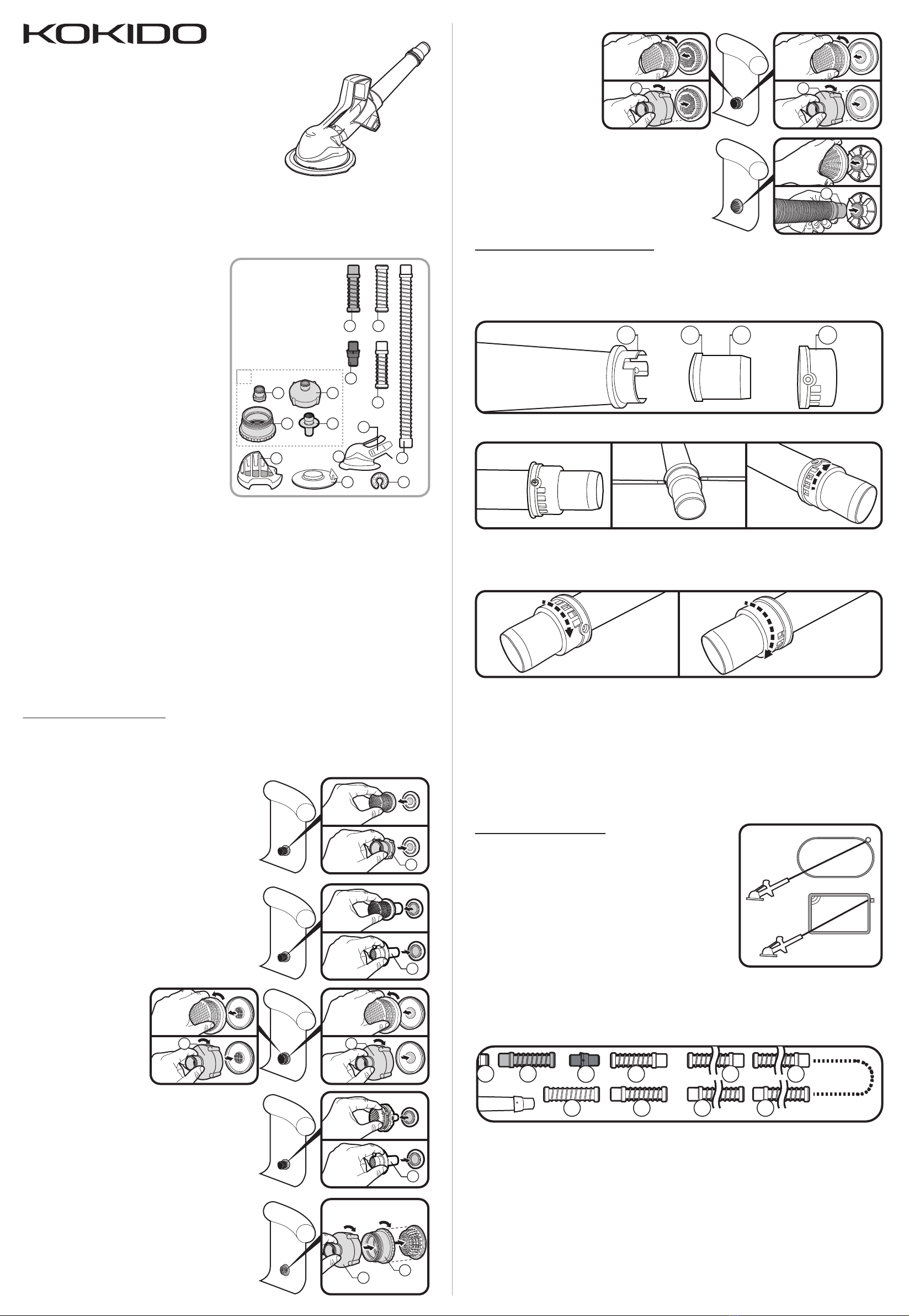
PRESSURE REGULATOR ADJUSTMENT
Excessive water flow from the pump/ filtration may result in the cleaner being stuck to the pool
bottom. On the contrary, insufficient water flow may inhibit the cleaner’s movement.
The cleaner includes a pressure regulator at the top that can be adjusted for pumps with a flow
rate up to 2000 gal/h (7.5m³/h). The default setting of this regulator is designed for use with
pumps with a flow rate of 1500 gal/h (5.6m³/h) or less. The pressure regulator is made up of parts
R1 thru R4 shown. (Fig.1)
WARNING! TURN OFF THE PUMP BEFORE ADJUSTING THE PRESSURE REGULATOR.
HOSE CONNECTOR ASSEMBLY
WARNING! TURN OFF THE FILTRATION SYSTEM PRIOR TO ASSEMBLING ANY HOSE CONNECTORS.
4 connectors (F1/F2/F3/F4) and Green short hose (A) enable the cleaner to fit most
brands of above ground pools on the market.
Select the right hose connector and refer to the following diagrams on how to establish a proper
connection to the strainer on the water outlet of your pool.
F4
Ø13/5in (40mm) Strainer plug with non-removable grid cover
Refer to the pool’s instruction manual to remove the strainer plug
from the water outlet and then insert "F4" connector as shown.
Note: if your pool’s strainer plug is attached to a hose with a
hose clamp and secured inside the pool water outlet, you may
need to loosen the hose clamp to release the strainer plug.
Pay attention not to detach the pool hose from the water outlet
when loosening the hose clamp. Remove the plug and insert
the "F4" connector into the water outlet as far as possible.
Tighten the hose clamp to secure the pool hose and the
connector to the water outlet.
F1
Ø13/5in (40mm) Strainer plug with removable grid cover
Detach the strainer cover and press "F1" on it.
F2F2
Ø3in (80mm) Strainer plug
with removable grid cover
Unscrew the strainer cover
and screw onto "F2".
A
Ø1
2/5
in (36mm) Strainer hole
Remove the grid cover and directly insert the cuff of hose
(A) into the strainer hole.
F4
Ø3in (
80mm
) Strainer plug with non-removable grid cover
Refer to the pool’s instruction manual to remove the strainer plug
from the water outlet and then insert "F4" connector as shown.
Note: if your pool’s strainer plug is attached to a hose with a
hose clamp and secured inside the pool water outlet, you may
need to loosen the hose clamp to release the strainer plug.
Pay attention not to detach the pool hose from the water outlet
when loosening the hose clamp. Remove the plug and insert
the "F4" connector into the water outlet as far as possible.
Tighten the hose clamp to secure the pool hose and the
connector to the water outlet.
F3
F2
Ø3
3/5
in (92mm) Strainer (with side thread)
Screw "F2" onto "F3", and then align and screw "F3" onto
the strainer.
F2F2
Ø4
1/3
in (110mm) Strainer
Unscrew the strainer cover
and screw "F2" onto the
middle thread of the strainer.
HOSE SECTIONS ASSEMBLY
The total length of assembled
hoses should be half to one hose
section length longer than the
length measured from the pool
strainer (water outlet) to the
farthest point in the pool. (Fig.2)
Refer to the diagram sequence below and connect the hose
sections accordingly:
• Strainer connector (F)
• Green short hose (A)
• Swivel (B)
• Male-female superflex hose (D)
• Male-female long hose (E)
• Superflex hose (D)
• Female-female short hose (C)
The quantity of male-female long hose (E) will depend on the length required for your pool and
must be connected between the 2 male-female superflex hose (D) below. Make sure to connect
the female-female short hose (C) to the cuff of the cleaner.
Fig.2
IMPORTANT NOTE:
- The swivel (B) allows the cleaner to turn smoothly. Do not alter its position or remove it.
For 610cm (20ft) round / rectangular pools, connect all 9 male-female long hose (E) and all
2 superflex short hoses (D) included.
For 457cm (15ft) & 485cm (16ft) round / rectangular pools, connect 7 male-female long hose (E)
and 2 superflex short hoses (D) included.
For pools in size smaller than 457cm (15ft), reduce the number of male-female long hose (E)
until total length of hose assembly is equivalent to the length from skimmer/dedicated suction line
to the farthest point in the pool plus a length equal to hose (E).
Immerse the hoses into the water one by one in the correct sequence to expel the air. Be sure to
complete the hose connection underwater. Alternately, you can connect all hoses together and place
either opening end towards the pool water inlet to let water flow expel the entrapped air.
Trapped air in your cleaning system may prevent the pump from operating smoothly. If this
happens, switch off your pump, open the release valve (if applicable) on your filter and let air
escape until only water comes out from the release valve, then close the valve.
Refer to your filtration manual on how to release the air.
A
DE E
DEE
B
C
F
Align the screw holes on R4 and R1 and tighten the screws accordingly once the ideal pressure
release setting is selected.
Remark: Pumps of the same horse power rating from different brands may vary in performance.
You may need to adjust the regulator for additional pressure release if the cleaner is stuck to the
pool floor and does not move because of excessive suction.
CAUTION! Do not expose the regulator to air while it is in operation, otherwise air might be
trapped and affect the cleaner / pool pump / filtration operation as a result.
Default setting (no opening
on grid) is designed to use
withpumps with a flow rate of
1500 gal/h (5.6m³/h) or less.
To alter the setting,
unscrew both screws
from R4.
To achieve minimum pressure
release, rotate R4 clockwiseuntil
a small opening is exposed on R1
(ensure the screw holes on R4
and R1 are aligned).
To achieve medium pressure release,
rotate R4 clockwise further, a bigger
opening (2 holes) on R1 is then exposed
(ensure the screw holes on R4 and R1
are aligned).
To achieve maximum pressure release, rotate R4
clockwise further and all holes should be unblocked
on R1 (ensure the screw holes on R4 and R1 are
aligned). This setting is recommended for pumps
with a flow rate up to 2000 gal/h (7.5m³/h).
xtrovac 70
AC55/AMZ
Ax1
x1
x1C
x2
D
B
K
G
H
F4F3
F2F1
x9
E
F
A.
B.
C.
D.
E.
F.
G.
H.
I.
J.
K.
Green short hose
Swivel
Female - Female short hose
Male - Female Superflex hose
Male-Female long hose
Hose Connectors
Cleaner head
Diaphragm
Filter cage
Base plate
Hose weight
I
J


