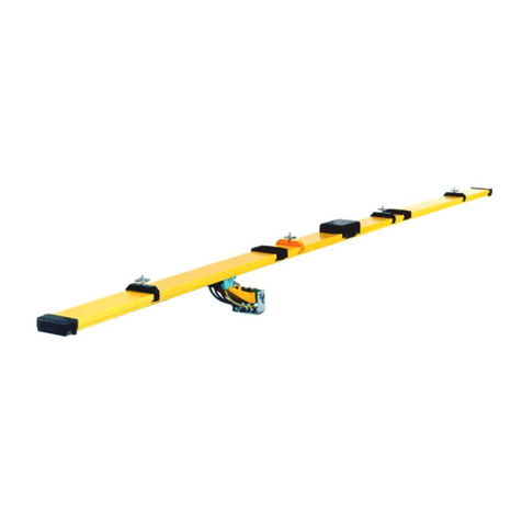
Delachaux Conductix-Wampfler 0314 Series User manual

Installation Manual
Festoon Systems for I-Beams
Program 0314
MAL0300-0001-EN
www.conductix.com translated document page 1 of 56

Installation Manual
Festoon Systems for I-Beams
Program 0314
MAL0300-0001-EN
www.conductix.com translated document page 2 of 56
Contents Page
1General information ................................................................................................................................................................. 5
1.1 Information about this installation manual ................................................................................................................... 5
1.2 Limitation of liability ..................................................................................................................................................... 5
1.3 Copyright ..................................................................................................................................................................... 6
1.4 Replacement parts ...................................................................................................................................................... 6
1.5 Material defects ........................................................................................................................................................... 6
1.6 Technical support ........................................................................................................................................................ 6
2Safety instructions.................................................................................................................................................................... 7
2.1 Explanation of symbols................................................................................................................................................ 7
2.2 Personnel requirements .............................................................................................................................................. 8
2.2.1 Qualifications................................................................................................................................................... 8
2.2.2 Unauthorized personnel.................................................................................................................................. 8
2.2.3 Training ........................................................................................................................................................... 8
2.3 Personal protective equipment .................................................................................................................................... 9
2.4 Intended use.............................................................................................................................................................. 10
2.5 Protective measures to be taken by the operator/user.............................................................................................. 11
2.6 Special hazards ......................................................................................................................................................... 12
2.7 Actions in the event of accidents and faults .............................................................................................................. 14
3Technical data........................................................................................................................................................................ 15
3.1 General information ................................................................................................................................................... 15
3.2 Interfaces................................................................................................................................................................... 15
3.3 Operating conditions.................................................................................................................................................. 15
3.4 Track beam................................................................................................................................................................ 16
3.4.1 Smoothing of welded track beams................................................................................................................ 17
3.4.2 Use of even welded track beams.................................................................................................................. 17
3.4.3 Girder joint for non-welded track beams ....................................................................................................... 18
3.4.4 Horizontal deviation of track beams.............................................................................................................. 19
3.4.5 Vertical deviation of track beams .................................................................................................................. 19
3.4.6 Poor horizontal alignment between the crane beam and the track beam..................................................... 20

Installation Manual
Festoon Systems for I-Beams
Program 0314
MAL0300-0001-EN
www.conductix.com translated document page 3 of 56
3.4.7 Poor vertical alignment between the crane beam and track beam ............................................................... 20
4Product description and mode of operation ........................................................................................................................... 21
4.1 Overview of the festoon system ................................................................................................................................ 21
4.2 Brief description......................................................................................................................................................... 22
4.3 Description of assemblies.......................................................................................................................................... 22
4.4 Working and danger areas ........................................................................................................................................ 25
4.5 Modes of Operation ................................................................................................................................................... 26
4.5.1 Automatic operation ...................................................................................................................................... 26
4.5.2 Manual operation .......................................................................................................................................... 26
5Transport, packaging and storage ......................................................................................................................................... 27
5.1 Transport ................................................................................................................................................................... 27
5.1.1 Safety instructions for transport .................................................................................................................... 27
5.1.2 Transport inspection...................................................................................................................................... 27
5.2 Packaging.................................................................................................................................................................. 28
5.3 Storage of packed parts ............................................................................................................................................ 28
6Installation and commissioning .............................................................................................................................................. 29
6.1 Safety ........................................................................................................................................................................ 29
6.2 Preparations .............................................................................................................................................................. 30
6.3 Installation ................................................................................................................................................................. 30
6.3.1 Assembling the festoon................................................................................................................................. 31
6.3.2 Adjusting the trolleys..................................................................................................................................... 31
6.3.3 Mounting the end clamp................................................................................................................................ 31
6.3.4 Fitting round cables....................................................................................................................................... 32
6.3.5 Laying flat cables .......................................................................................................................................... 33
6.4 Testing and commissioning ....................................................................................................................................... 34
6.4.1 Commissioning test list ................................................................................................................................. 35
7Operation ............................................................................................................................................................................... 39
7.1 Safety ........................................................................................................................................................................ 39
7.2 Functioning................................................................................................................................................................ 40
8Maintenance and servicing .................................................................................................................................................... 41
8.1 Safety ........................................................................................................................................................................ 41

Installation Manual
Festoon Systems for I-Beams
Program 0314
MAL0300-0001-EN
www.conductix.com translated document page 4 of 56
8.2 Maintenance/inspection plan ..................................................................................................................................... 42
8.2.1 Inspection with the system at a standstill...................................................................................................... 43
8.2.2 Inspection with the system moving ............................................................................................................... 44
8.2.3 Logging ......................................................................................................................................................... 44
8.2.4 Maintenance of the festoon system .............................................................................................................. 45
8.2.5 Wearing parts................................................................................................................................................ 46
8.2.6 Wear limits .................................................................................................................................................... 47
8.2.7 Repeat inspections........................................................................................................................................ 47
8.2.8 Repair............................................................................................................................................................ 47
9Troubleshooting ..................................................................................................................................................................... 48
10 Dismantling and disposal ....................................................................................................................................................... 49
10.1 Safety ........................................................................................................................................................................ 49
10.2 Dismantling................................................................................................................................................................ 50
10.3 Disposal..................................................................................................................................................................... 50
11 Additional Documents ............................................................................................................................................................ 51
11.1 Declaration of incorporation....................................................................................................................................... 51
11.2 Documentation for electrical equipment .................................................................................................................... 52
11.3 Spare parts list........................................................................................................................................................... 52
11.4 Product observations................................................................................................................................................. 53
11.5 Final inspection protocol............................................................................................................................................ 55

Installation Manual
Festoon Systems for I-Beams
Program 0314
MAL0300-0001-EN
www.conductix.com translated document page 5 of 56
1General information
1.1 Information about this installation manual
These assembly instructions make it possible for you to work with the festoon system safely and efficiently.
The assembly instructions are a part of the festoon system, and must be kept accessible to personnel at all times in the immediate
vicinity of the festoon system. Personnel must read these instructions carefully and understand them before starting any work. The
basic prerequisite for safe work is compliance with all safety and operating guidelines in this installation manual. Furthermore, local
accident protection regulations and general safety regulations apply for the area of use of the festoon system.
Illustrations are provided for basic understanding and may deviate from the actual implementation of the festoon system.
In addition to this installation manual, the instructions located in the appendices for the individual assembled components also
apply.
1.2 Limitation of liability
All data and information in this installation manual has been compiled while taking the valid standards and regulations as well as
the state-of-the art and our long years of experience and knowledge into consideration.
The manufacturer accepts no liability for damage resulting from:
Failure to comply with the installation manual
Improper use
Use by untrained personnel
Unauthorized modifications
Technical changes
Use of unauthorized replacement parts and accessories.
The actual scope of delivery may differ from the explanations and descriptions provided here if the model in question is a special
one, if additional equipment has been ordered or due to recent technical changes.
The obligations agreed upon in the delivery agreement and our General Terms and Conditions of business apply, as do the
delivery conditions of the manufacturer and the legal regulations applicable at the time the contract was concluded.
All products are subject to technical modifications, within the context of improvement of function and further development.

Installation Manual
Festoon Systems for I-Beams
Program 0314
MAL0300-0001-EN
www.conductix.com translated document page 6 of 56
1.3 Copyright
These assembly instructions are subject to copyright, and are exclusively intended for internal use.
Provision of the assembly instructions to third parties, duplications in any form – even in part – as well as the reuse and/or
disclosure of their content are not permitted without the written approval of the manufacturer, except for internal use.
Breach or infringement will result in liability for damages. Our right to further claims remains unaffected.
1.4 Replacement parts
WARNING!
Incorrect replacement parts are a safety hazard!
Incorrect or faulty replacement parts can impair safety and result in damage, malfunctions or
complete failure.
Therefore:
- Use only original replacement parts from the manufacturer!
Replacement parts can be ordered from your contracted dealer or directly from the manufacturer. See the last page of these
assembly instructions for the address.
1.5 Material defects
The terms governing material defects can be found in the General Terms and Conditions of business.
1.6 Technical support
Our customer support staff is available for technical support. See the last page of these assembly instructions for contact
information.
We are also always interested in new information, experiences and feedback from the field that can help us improve our products.

Installation Manual
Festoon Systems for I-Beams
Program 0314
MAL0300-0001-EN
www.conductix.com translated document page 7 of 56
2Safety instructions
2.1 Explanation of symbols
Safety and hazard information is identified in this installation manual by symbols. Safety instructions are introduced by signal
words that indicate the degree of the hazard. Always observe safety and hazard instructions, and work carefully to avoid accidents,
bodily injury and damage to property!
DANGER!
... indicates an immediately hazardous situation, which if not avoided, may result in death or serious
injury.
WARNING!
... indicates a possibly hazardous situation, which if not avoided, may result in death or serious
injury.
WARNING!
... Indicates a potential fire risk if not prevented.
WARNING!
... Indicates a possible danger from electricity, which if not avoided, may result in death or serious
injury.
CAUTION!
…Indicates a potential hazard that may result in moderate or minor injury and property damage if
not avoided.
NOTE!
Tips and recommendations:
… Provide useful tips and recommendations as well as information for efficient and trouble-free
operation.

Installation Manual
Festoon Systems for I-Beams
Program 0314
MAL0300-0001-EN
www.conductix.com translated document page 8 of 56
2.2 Personnel requirements
2.2.1 Qualifications
WARNING!
Inadequately trained persons are at risk of injury!
Improper use can result in serious injury to persons and property.
Therefore:
- All activities must be carried out by qualified staff!
The following qualifications have been mentioned in this installation manual for different areas of operation:
Trained personnel/operators
have been instructed by the operator about the tasks assigned to him/her and the possible hazards resulting from improper
use.
Specialist personnel
consists of persons capable of performing assigned tasks and independently identifying and avoiding potential hazards based
on their specialist training, knowledge and experience as well as their understanding of the applicable regulations.
Only persons who can be expected to perform their work reliably are acceptable personnel. Persons whose responsiveness is
influenced by drugs, alcohol, or medications, for example, are not permitted.
When selecting personnel, all age- and occupation-specific regulations applicable at the place of use must be observed.
2.2.2 Unauthorized personnel
WARNING!
Danger due to unauthorized personnel!
Unauthorized persons who do not meet the requirements described here are not acquainted with the
dangers in the working area.
Therefore:
- Keep unauthorized personnel away from the working area.
- In case of doubt, address such persons and direct them away from the working area.
- Stop work as long as unauthorized persons are in the working area.
2.2.3 Training
Before commissioning the equipment, personnel must be trained by the owner. For better tracking, log the instruction as follows:
Date
Name
Type of training
Training given by
Signature
Fig. 1: Example of instruction log

Installation Manual
Festoon Systems for I-Beams
Program 0314
MAL0300-0001-EN
www.conductix.com translated document page 9 of 56
2.3 Personal protective equipment
Always wear:
For all work, always wear:
Protective work clothing
are tightly fitting working clothes with low resistance to tearing, close-fitting
sleeves and no protruding parts. They serve primarily as protection against
entrapment by moving machine parts.
Rings, neck chains or other items of jewelry must not be worn.
Protective footwear
used to protect from falling heavy parts and slipping on slippery floors.
For special tasks, wear:
When carrying out particular tasks, special safety gear is required. The
individual sections of these instructions specify this gear in detail. The
following particular safety gear is explained below:
Protective gloves
for the protection of hands from friction, scrapes, stabbing, or deep wounds, as
well as from contact with hot surfaces.
Protective headgear
for protection from falling and flying parts and materials.
Safety goggles
for eye protection.

Installation Manual
Festoon Systems for I-Beams
Program 0314
MAL0300-0001-EN
www.conductix.com translated document page 10 of 56
2.4 Intended use
The festoon system is exclusively designed and built for the intended use described here.
The Series 0314 festoon system and its components may only be used for the construction and operation of power supply systems
for rail-mounted, mobile consumers such as cranes and lifting accessories in industrial applications.
Other applications are only permitted with the written approval of Conductix-Wampfler.
WARNING!
Hazard due to improper use!
Any application that deviates from or goes beyond the intended use of the festoon system can result
in a hazardous situation.
Therefore:
Use the festoon system only for its intended use.
- Follow all information in this installation manual strictly.
- The following uses of the festoon system are prohibited.
Non-intended use particularly includes the following:
- Use of the festoon system with accessories not permitted and not authorized by the
manufacturer.
- Operation of the festoon system by uninstructed personnel.
- Operation of the festoon system without its being installed on a proper foundation/floor.
- Exceeding the rated load-bearing capacities
- Exceeding projected speeds
- Excessive acceleration
- Use of unsuitable cables
- Changes to atmospheric conditions
- Change in the anticipated location of use
We do not accept any liability for damage arising from improper use.
The operator bears sole liability for all damage that result from improper use.

Installation Manual
Festoon Systems for I-Beams
Program 0314
MAL0300-0001-EN
www.conductix.com translated document page 11 of 56
2.5 Protective measures to be taken by the operator/user
The festoon system is used in an industrial setting. The operator of the festoon system is thus subject to legal requirements related
to workplace safety. In addition to the safety instructions in these assembly instructions, all safety, accident protection, and
environmental regulations valid in the place of operation of the festoon system must also be observed. This particularly applies to
the following:
The operator must ensure that the festoon system will only be used for its intended purpose.
The operator must inform him/herself of applicable workplace safety guidelines and identify any additional hazards that may
arise under the specific working conditions at the place of use of the festoon system. This knowledge must be expressed in
the form of operating instructions for the operation of the device. .
During the entire time the festoon system is in use, the operator must check that these operating instructions still correspond to
the current state of regulations and adapt them as necessary.
The operator must clearly manage and define responsibilities for installation, operation, troubleshooting and maintenance.
The operator must ensure that all employees involved with the festoon system have read and understood these assembly
instructions. The owner must also train the personnel at regular intervals and inform them of hazards.
The owner must provide personnel with the necessary protective equipment.
Furthermore, the operator is responsible for ensuring that the festoon system is always in a technically perfect condition. The
following thus apply:
The operator must ensure that the service intervals described in this installation manual are observed.
The operator must have all safety systems regularly inspected for functionality and completeness.

Installation Manual
Festoon Systems for I-Beams
Program 0314
MAL0300-0001-EN
www.conductix.com translated document page 12 of 56
2.6 Special hazards
The following section lists residual risks determined on the basis of a risk assessment.
Follow the safety instructions listed here and the warnings in other sections of this installation manual in order to reduce health
hazards and avoid dangerous situations.
WARNING!
Risk of death due to suspended loads!
When lifting loads, there is a risk of death due to parts falling or swinging out of control.
Therefore:
- Never walk under suspended loads.
- Only move loads under supervision.
- Follow the specifications for the attachment points provided
- Do not lash to protruding machine parts or eyelets on attached components. Be sure the lashing
elements are firmly seated.
- Use only authorized lifting accessories and lashing elements with sufficient load capacity
- Do not use torn or worn ropes or straps
- Do not attach ropes or straps at sharp corners and edges, and do not knot or twist them
- Set loads down when leaving the workplace
WARNING!
Danger of injury from moving components!
Incautious handling of the festoon system can lead to severe injury or damage to the festoon system.
Therefore:
- Be sure that the festoon system does not start by itself.
- While it is moving, do not reach into moving parts, particularly the interface between the buffer and
buffer plate.
- Block off the dangerous area under the system.
DANGER!
Danger of injury due to electrocution!
Danger of severe injury or death due to electric current.
Therefore:
- Before working on the cable-festoon system, the system must be disconnected from power using
the main switch, and secured against unauthorized, unintentional, and/or erroneous activation. In
special cases where there is no main switch, the power disconnection must be carried out
according to the specifications of the system manufacturer. Check that parts disconnected from
power are voltage free, then ground and short-circuit them. Insulate adjacent live parts!
- Before each commissioning, an insulation test must be carried out in accordance with the local
technical standards, guidelines, and law.

Installation Manual
Festoon Systems for I-Beams
Program 0314
MAL0300-0001-EN
www.conductix.com translated document page 13 of 56
Warning!
Risk of fire!
Risk of fire if undersized cables are used!
Therefore:
- The required cable cross-sections must be adhered to.
CAUTION!
Danger of tripping on projecting parts!
When working on the festoon system, there is a risk of tripping.
Therefore:
- When walking in the work and danger area, be careful of projections and depressions in the floor.
No loose objects may be left on the floor.
WARNING!
Danger of crushing!
When moving the festoon system, there is a danger of crushing limbs between the buffer and buffer
plate, as well as between the carriage and the track carrier.
Therefore:
- Do not enter the danger area of the cable-festoon system when the system is moving
CAUTION!
Trap!
There is a danger of being trapped when the cable-festoon system is moving.
Therefore:
- Do not enter the danger area of the cable-festoon system when the system is moving

Installation Manual
Festoon Systems for I-Beams
Program 0314
MAL0300-0001-EN
www.conductix.com translated document page 14 of 56
2.7 Actions in the event of accidents and faults
Measures to take in the event of accidents:
Take first-aid measures.
Remove persons from the danger zone.
Inform responsible parties at the place of operation.
Alarm the rescue services.
Make access ready for rescue vehicles.
Measures to take in the event of malfunctions:
Secure the work area against entry.
Involve qualified personnel for fault analysis.
Involve authorized personnel for maintenance and repair.
Shut down the system and secure it against unauthorized, unintentional, and/or erroneous activation.
If injury to person or property occurs during a breakdown then Conductix-Wampfler must be informed immediately.

Installation Manual
Festoon Systems for I-Beams
Program 0314
MAL0300-0001-EN
www.conductix.com translated document page 15 of 56
3Technical data
3.1 General information
Designation
Value
Notes
Max. load capacity
10 - 20 kg
Depending on the number of rolls
Max. travel speed
50 m/min
3.2 Interfaces
Mechanical:
Machine
Part
Load-bearing structure
End clamp, towing trolley
Cables
Overlay, conductor holder
Electrical, data, and media:
Machine
Part
Switching cabinet
Cables
Media supply
Cables
Consumer
Cables
3.3 Operating conditions
Environment:
Designation
Value
Notes
Temperature range
-20 to +60°C
Relative humidity, maximum
100%
Max. operating speed
17.2 -< 20.8 m/sec
Max. wind speed
> 32.7 m/sec

Installation Manual
Festoon Systems for I-Beams
Program 0314
MAL0300-0001-EN
www.conductix.com translated document page 16 of 56
3.4 Track beam
The operator is basically responsible for ensuring that the track carrier is securely fastened as well as checking it for wear,
corrosion or defects.
The following procedures are to be observed when installing the track beam:
In general, track beams are to be protected from corrosion using appropriate measures.
The running surfaces of the main rollers and the horizontal guide rollers must be clean and free of objects or defects that could
damage the rollers (scratches, cracks, holes, uneven segments, etc.).
If multiple beams are welded together, they must all have the same measurements, shape and positional tolerances.
The beam flanges are to be aligned with particular care in horizontal and vertical planes.
Track beams that have been damaged during transport or rolling are not permitted for use.
Modified areas (from welding, sanding, etc.) on the track beam are to be protected from corrosion with appropriate measures.
There may be no projecting contours on the sides of the track area or under the track beam.

Installation Manual
Festoon Systems for I-Beams
Program 0314
MAL0300-0001-EN
www.conductix.com translated document page 17 of 56
3.4.1 Smoothing of welded track beams
Bumps and uneven areas on all sides of the welded track beams are to be sanded smooth for a length of 100 mm.
Required tools and materials:
NOTE!
Fig. 2: Smoothing of welded track beams
3.4.2 Use of even welded track beams
Welded joints on the track beams must be even at points that could come into contact with the cable trolleys. Mounting elements
and suspended objects that could come into contact with the trolleys are not permitted.
Fig. 3: Use of even welded track beams
No uneven areas, mounting elements, suspended
objects, etc.

Installation Manual
Festoon Systems for I-Beams
Program 0314
MAL0300-0001-EN
www.conductix.com translated document page 18 of 56
3.4.3 Girder joint for non-welded track beams
For non-welded girder joints, the gap between beams may be at most 8 mm. The cut is at a 45° angle.
Required tools and materials:
NOTE!
Fig. 4: Girder joint for non-welded track beams
For non-welded girder joints, the horizontal and vertical deviation of the opposing sides of the joint may be at most 2 mm.
Transitions must be ground smooth within about 100 mm of the beginning of the cut. All transitions must be beveled and
rounded.
Required tools and materials:
NOTE!
Fig. 5: Girder joint for non-welded track beams
Edges chamfered and
rounded
Edges chamfered and
rounded
Horizontal and vertical deviation 2 mm

Installation Manual
Festoon Systems for I-Beams
Program 0314
MAL0300-0001-EN
www.conductix.com translated document page 19 of 56
3.4.4 Horizontal deviation of track beams
The horizontal deviation over the length of the track beam may not exceed 5 mm. For lengths shorter than 2 m, deviation may not
exceed 2 mm.
Required tools and materials:
NOTE!
Fig. 6: Horizontal deviation of track beams
3.4.5 Vertical deviation of track beams
The vertical deviation over the length of the track beam may not exceed 5 mm. For lengths shorter than 2 m, deviation may not
exceed 2 mm.
Fig. 7: Vertical deviation of track beams

Installation Manual
Festoon Systems for I-Beams
Program 0314
MAL0300-0001-EN
www.conductix.com translated document page 20 of 56
3.4.6 Poor horizontal alignment between the crane beam and the track beam
The vertical alignment gap between the crane beam and track beam must not exceed 7.5 mm. This tolerance should include a
possible alignment deviation of the trolley winch.
Required tools and materials:
NOTE!
Fig. 8: Poor horizontal alignment between the crane beam and the track beam
3.4.7 Poor vertical alignment between the crane beam and track beam
The vertical alignment gap between the crane beam and track beam must not exceed 15 mm. This tolerance should include a
possible alignment deviation of the trolley winch.
Required tools and materials:
NOTE!
Fig. 9: Poor vertical alignment between the crane beam and track beam
Crane beam
Track beam
Crane beam
Track beam
Table of contents
Other Delachaux Industrial Equipment manuals
