Delachaux Conductix Wampfler 0831 User manual

Mounting Instructions
Multipole Conductor Rail System
Program 0831
MV0831-0006e-EN
www.conductix.com translated document Page 1 of 32
Order Number
0831xx-…
Contents
1System description......................................................................................................................................................................2
2Intended use ...............................................................................................................................................................................3
3Control components....................................................................................................................................................................4
4Assembly ....................................................................................................................................................................................5
4.1 Adjusting the lengths ...................................................................................................................................................7
4.2 Installation of the fixed point and the hanger clamp ....................................................................................................8
4.2.1 Fixed point ...................................................................................................................................................................8
4.2.2 Hanger clamps ............................................................................................................................................................9
4.2.3 (Optional) safety catching device ..............................................................................................................................12
4.3 Click the conductor rail into its place .........................................................................................................................13
4.4 Position of the end and center feeds .........................................................................................................................14
4.5 Connect the conductor rail.........................................................................................................................................15
4.6 Remedy in case of damaged connecting pins...........................................................................................................22
5Installation of expansion elements............................................................................................................................................23
6Assembly of the current collectors ............................................................................................................................................25
7Screw tightening torques ..........................................................................................................................................................27
8Index .........................................................................................................................................................................................28
9Index of the animations.............................................................................................................................................................32
Mounting Instructions
Multipole Conductor Rail System
Program 0831
MV0831-0006e-EN
www.conductix.com translated document Page 2 of 32
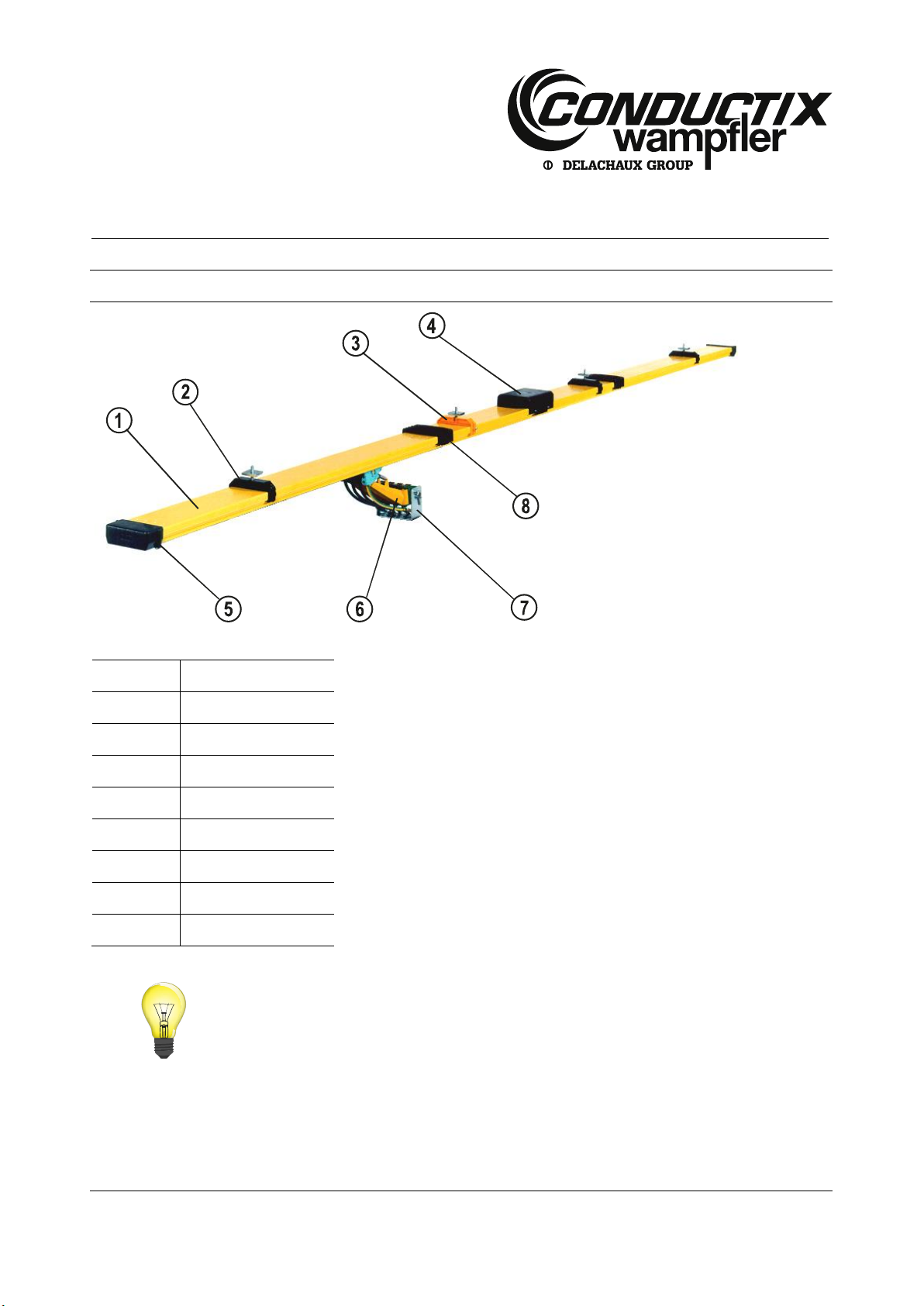
1System description
Fig. 1: Components of the multipole conductor rail system program 0831
Item
Designation
1
Conductor rail
2
Hanger clamp
3
Fixed point
4
Centre feed
5
End cap
6
Current collector
7
Towing unit
8
Connector
See chapter 8 for other components of the multipole conductor rail system.

Mounting Instructions
Multipole Conductor Rail System
Program 0831
MV0831-0006e-EN
www.conductix.com translated document Page 3 of 32
2Intended use
The multipole conductor rail system serves for the energy and data transmission on indoor systems and weatherproof outdoor
systems on straight travel paths.
Possible fields of application:
Storage and retrieval equipment
Cranes
Transport vehicles and special machines.
The following conditions are applicable for the use of the multipole conductor rail systems:
Designation
Value, unit
Additional information
Range of application
The multipole conductor rail system 0831 is an electrical
energy supply for track-guided, mobile consumers indoors, in
storage areas not accessible for the public.
Installation height
Max. 3000 mm
For the installation beyond 3000 mm installation height or on
systems with a strong risk potential we have provided safety
catching devices that can be supplied as an option. See
chapter 5 for further information.
Installation position
Horizontal installation position with vertical engagement,
optional current collector engagement from underneath.
Vertical engagement e.g. at the pole is possible, please contact
us for advice and provide a safety catching device.
Max. Support distance (distance
between the hanger clamps)
1000 mm
If suspension distances of more than 1000 mm are required,
you can combine the multipole conductor rail system with the
assembly system ProShell (see „KAT0800-0003“).
Max. operating voltage
See type plate
The type plate is located on the end and center feed
Nominal current
Mounting Instructions
Multipole Conductor Rail System
Program 0831
MV0831-0006e-EN
www.conductix.com translated document Page 4 of 32
3Control components
Prior to mounting check the goods (consisting of several packages) for completeness and damage by means of the delivery note:
Ensure that all required packages are on site.
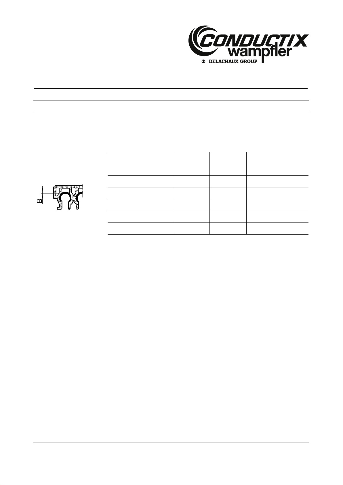
The conductor rails are available with various nominal values and of various conductor materials:
Strength of the conductor
materials
Fig. 2: Strength of the conductors
Conductor material
Ampere I
Catalog
number
B
[mm]
Steel (galvanized)
32 A
083112-...
1
copper
60 A
083115-...
0.6
copper
100 A
083116-...
1
copper
125 A
083117-...
1.4
Data-Metal
10 A
083118-...
1
Mounting Instructions
Multipole Conductor Rail System
Program 0831
MV0831-0006e-EN
www.conductix.com translated document Page 5 of 32
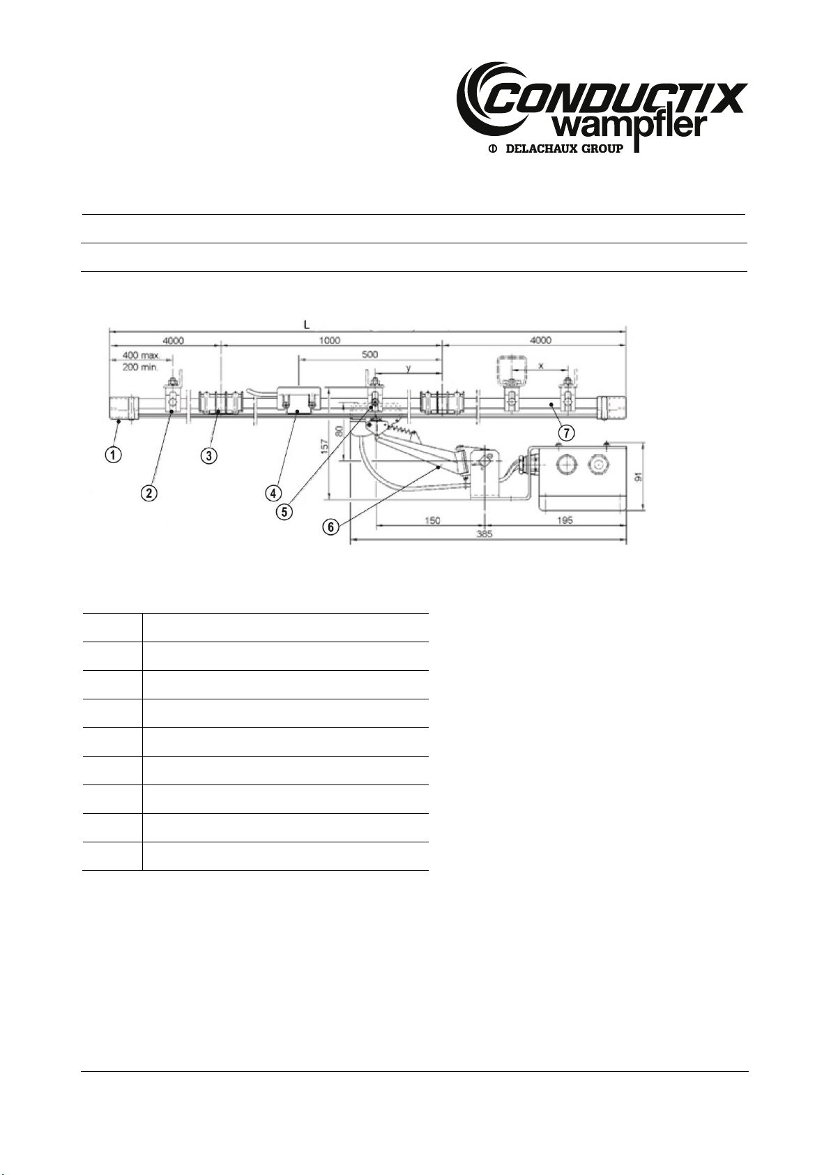
4Assembly
The system sketch shows the mounting distances to the connectors and end and center feed:
Fig. 3: System sketch
See Fig 5 for suspension distance (x) and center distance (y)
Item
Designation
1
End cap or end feed (not illustrated)
2
Hanger clamp
3
Connector
4
Centre feed
5
Fixed point
6
Current collector (vertical engagement)
7
Conductor rail
L
Total length of the system

Mounting Instructions
Multipole Conductor Rail System
Program 0831
MV0831-0006e-EN
www.conductix.com translated document Page 6 of 32
Use the QR code („click“ or „scan“), to watch our animation
MultiLine 0831 Overview
Use the QR code („click“ or „scan“), to watch our animation
Console Assembly
Use the QR code („click“ or „scan“), to watch our animation
Console Aligning
Mounting Instructions
Multipole Conductor Rail System
Program 0831
MV0831-0006e-EN
www.conductix.com translated document Page 7 of 32
4.1 Adjusting the lengths
The multipole conductor rail systems are supplied by standard in lengths of 4000 mm, 3000 mm, 2000 mm and 1000 mm. All kinds
of system lengths can thus be realized.
Always make the length adjustment at the finally mounted conductor rail!
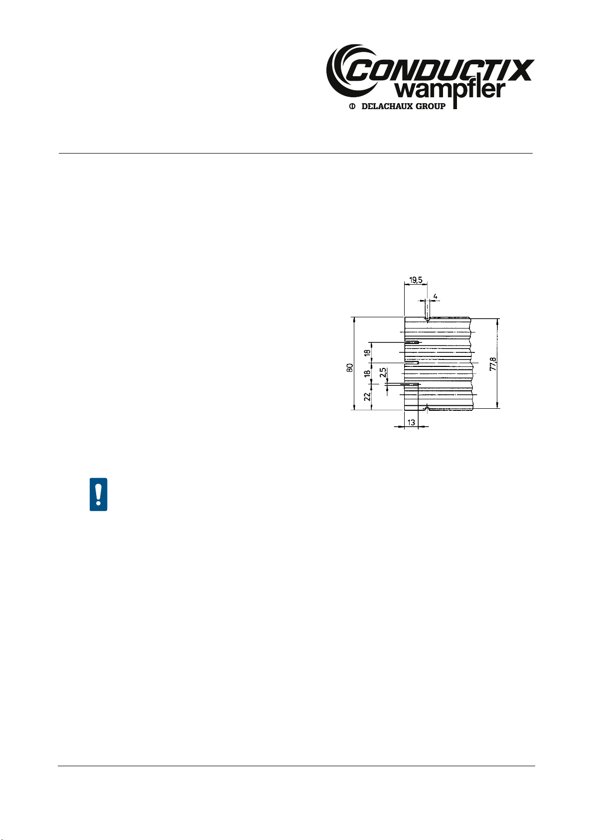
Shorten conductor rail:
Saw off the conductor rail to the requested length.
Saw the slots according to the sketch.
Deburr the terminations of the conductor rail and the slots with a not
too rough file.
Remove dirt and shavings.
Put on the end cap and bore out the insulating profile (through the
borings 4 mm in the end cap).
See chapter 4.4 for the installation of the end cap.
Fig. 4: Dimensions for slots at the end of the conductor rail
CAUTION!
Bring the connecting point into its original state!
Bring the connecting point into its original state, if a conductor rail must be shortened along the track.
Conductor rails that have not been deburred will cause increased abrasion of the collector heads:
Ensure that the conductor rails (conductors) are properly deburred at their terminations (see Fig. 13)

Mounting Instructions
Multipole Conductor Rail System
Program 0831
MV0831-0006e-EN
www.conductix.com translated document Page 8 of 32
4.2 Installation of the fixed point and the hanger clamp
4.2.1 Fixed point
The fixed point secures the multipole conductor rail system against displacement. The fixed point consists of an orange hanger
clamp and a self-tapping screw.
Working steps:
Put the fixed point preferably in the center of the multipole conductor rail system. Particularly on long systems this will
guarantee a consistent expansion of the multipole conductor rail system in both directions.
When using a center feed install the fixed point next to it, if possible. See chapter 7 for the screw tightening torques.
Fix the fixed point with the enclosed self-tapping screw at the conductor rail.
Use the QR code („click“ or „scan“), to watch our animation
Tightening the Anchor Point Screw

Mounting Instructions
Multipole Conductor Rail System
Program 0831
MV0831-0006e-EN
www.conductix.com translated document Page 9 of 32
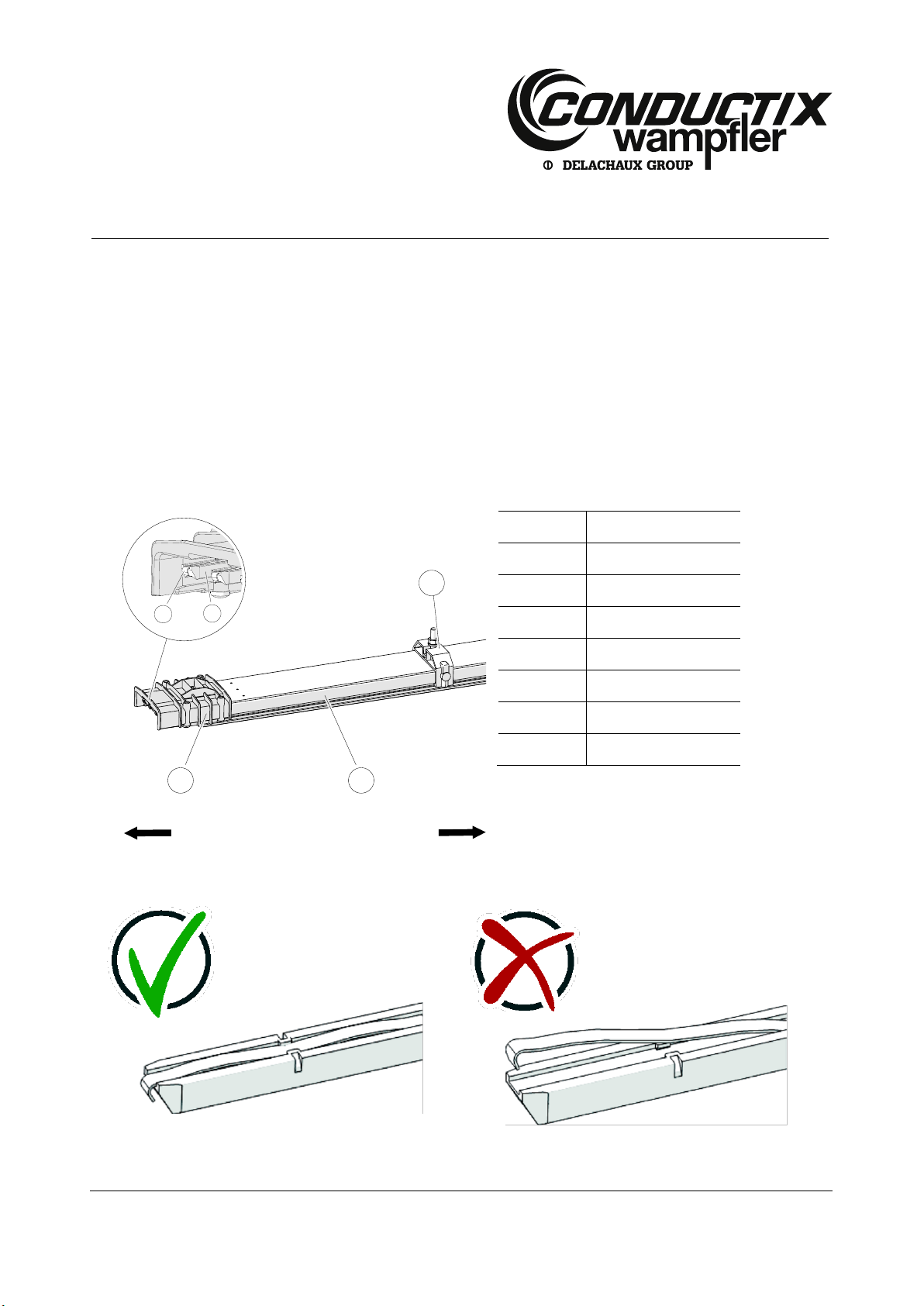
4.2.2 Hanger clamps
The hanger clamps are designed as sliding suspensions (see Fig. 3):
Suspension distance x
Center distance y
1000 mm
System length 50.000 mm
System length > 50.000 mm
190 10 mm
320 10 mm
Fig 5: Dimensions of the suspension distance and the center distance
CAUTION!
Ensure a correct alignment of the hanger clamps!
Height offset or angle error during the assembly may result in jamming of the conductor rail on thermal
expansion. This will result in wavy conductor rails!
Pay attention to a correct alignment of the hanger clamps, in order to ensure gliding of the rail in the
hanger clamp on thermal expansion.
Working steps:
Observe the minimum distances to the connector points and feeds for the position of the hanger clamps, in order to avoid
collisions and inhibitions in case of linear extensions. See Fig 5 for suspension and center distance.
Install the hanger clamp. See chapter 7 for the screw tightening torques.
If the multipole conductor rail system is in a vertical arrangement, the clip (see Fig. 6) must point upward.
Fig. 6: In vertical position the clip points upward
In case of collisions/overlapping along the track, there must be an assembly fault at the hanger clamps:
Replace the respective hanger clamp. See Fig 5 for suspension and center distance.
Item
Designation
1
Clip

Mounting Instructions
Multipole Conductor Rail System
Program 0831
MV0831-0006e-EN
www.conductix.com translated document Page 10 of 32
Fig. 7: Distribution of hanger clamps, rail connectors and fixed points
Item
Designation
1
Conductor rail
2
Hanger clamp
3
Connector
4
Fixed point
Max. length of track (without expansion units):
Length
Temperature
Without expansion units
On systems with lengths L ≤ 200.000 mm
Systems in a normal temperature range and a max.
temperature change of 30 K
With expansion units
On systems with lengths L ≤ 200.000 mm
Changed range of temperature (see chapter 5)
The multipole conductor rail system can be combined with an assembly system ProShell!
If suspension distances (distance between the hanger clamps) of more than 1000 mm are
required, you can combine the multipole conductor rail system with the assembly system ProShell.
ProShell is a modular supporting structure for the Conductix-Wampfler conductor rail systems 0812
and 0831. With ProShell you can choose a suspension distance of up to 3200 mm. See „KAT0800-
0003“ for further information.
Mounting Instructions
Multipole Conductor Rail System
Program 0831
MV0831-0006e-EN
www.conductix.com translated document Page 11 of 32
Use the QR code („click“ or „scan“), to watch our animation
Hanger Clamp and Anchor Point Assembly (horizontal operation)
Use the QR code („click“ or „scan“), to watch our animation
Hanger Clamp and Anchor Point Assembly (vertical operation)

Mounting Instructions
Multipole Conductor Rail System
Program 0831
MV0831-0006e-EN
www.conductix.com translated document Page 12 of 32
4.2.3 (Optional) safety catching device
The conductor rail is equipped with a catching clip including catch-rope, if the installation height is more than 3.000 mm or there is
an increased risk potential. In the event of a collision or another damaging event the multipole conductor rail system will be secured
by the catch-rope at the framework of the supporting construction. The safety catching device consists of 2 clamp halves including
mounting screws and a catch-rope. If required, please ask your distribution partner.
Catalog number of the safety catching device: 08-S280-0613
Working steps:
Lay both clamp halves to the back of the rail and screw the two components together by means of the enclosed screw/bolt.
Attach the catch-rope to the on-site structure and connect it with the clamp.
Fig. 8: Optional safety catching device
Use the QR code („click“ or „scan“), to watch our animation
Safety Catching Device (vertical operation)

Mounting Instructions
Multipole Conductor Rail System
Program 0831
MV0831-0006e-EN
www.conductix.com translated document Page 13 of 32
4.3 Click the conductor rail into its place
Observe the alignment of the conductor rail.
Click the conductor rail into the hanger clamp.
CAUTION!
In a vertical arrangement the clip must point upward (see Fig. 6)!
Fig. 9: Click the conductor rail into the hanger clamp.
Use the QR code („click“ or „scan“), to watch our animation
Conductor Rail Clipping and Connecting

Mounting Instructions
Multipole Conductor Rail System
Program 0831
MV0831-0006e-EN
www.conductix.com translated document Page 14 of 32
4.4 Position of the end and center feeds
The position of the end and center feeds is specified by the connecting points on site. The alignment of the end and center feed,
among others, determines the position of the protective earth conductor.
The connecting cables must not exert any tensile strength onto the end or center feed. A tensile force may, e.g. be generated by
thermal expansion of the multipole conductor rail system. Therefore the cables must be installed flexibly at the end or center feed
(e.g. by sufficiently large cable loops). See Fig. 3 for the arrangement of the mounting distances to the connectors and end and
center feed.
Use the QR code („click“ or „scan“), to watch our animation
Center Feed Mounting
Use the QR code („click“ or „scan“), to watch our animation
End Feed Assembly
Mounting Instructions
Multipole Conductor Rail System
Program 0831
MV0831-0006e-EN
www.conductix.com translated document Page 15 of 32
4.5 Connect the conductor rail
Prerequisites:
The hanger clamps are mounted as in chapter 4.
The conductor rails that are to be connected must be completely clicked into the hanger clamps.
The connector pins with spring elements must be straight and undamaged.
Each conductor rail is equipped with sockets on both sides. On one side connecting pins with spring elements have been
introduced into the sockets and a connector cap has been pre-assembled. The connecting pins must be pushed into the sockets as
far as they will go until they touch the PVC profile.
Fig. 10: Pin side in detail
Fig. 11:Correct position of the clamp
Fig. 12:Wrong position of the clamp
5
4
B
A
3
1
2
Item
Designation
1
Connecting pin
2
Spring element
3
Connector cap
4
Insulating profile
5
Hanger clamp
A
Pin side
B
Socket side

Mounting Instructions
Multipole Conductor Rail System
Program 0831
MV0831-0006e-EN
www.conductix.com translated document Page 16 of 32
Fig. 13:Detailed view socket side
Fig. 14:Detailed view pin side
Item
Designation
1
Insulating profile
2
Connector cap
3
Cross-head screw
4
Socket
5
Pin side
6
Connecting clamp
7
Conductor rail (conductor)
8
Connecting pin with spring element
9
Stop position of the connecting pin
1
6
7
4
1
2
3
9
7
8
5
6

Mounting Instructions
Multipole Conductor Rail System
Program 0831
MV0831-0006e-EN
www.conductix.com translated document Page 17 of 32
CAUTION!
Prior to making a rail connection, check if connecting pin and socket are in perfect condition!
On the pin side it must be checked if:
Connecting pins and connecting clamps are existing and in the same position (see Fig. 10, item 1
and Fig. 14, item 6),
Connecting pins with spring are fitting and not deformed (see Fig. 10, item 1).
On the pin side it must be checked if:
Connecting clamp in the reception area for the connecting pin (socket side) is available and in a
correct position (see Fig. 13, item 6).
CAUTION!
Always insert the side with the connecting pins into the socket, never vice versa!
The connecting pins will be damaged, if the socket side is forcibly pushed onto the connecting pins.
Fig. 15:Mount the pin side onto the socket side
Fig. 16:Never push the socket onto the connecting pins!
When inserting the connecting pins, ensure a precise alignment on the sockets.
Mounting Instructions
Multipole Conductor Rail System
Program 0831
MV0831-0006e-EN
www.conductix.com translated document Page 18 of 32
Working steps:
The assembly always starts at one end of the multipole conductor rail systems and not in the center:
Click the first conductor rail into the hanger clamp in such a way that the pin end is the end (or the beginning) of the multipole
conductor rail system. The socket end points in the direction where the installation is made.
Pull the connecting pins out of the pin end of the first conductor rail and put them aside (can be used as spare parts).
Dismount connector cap and put it aside (can be used as spare part).
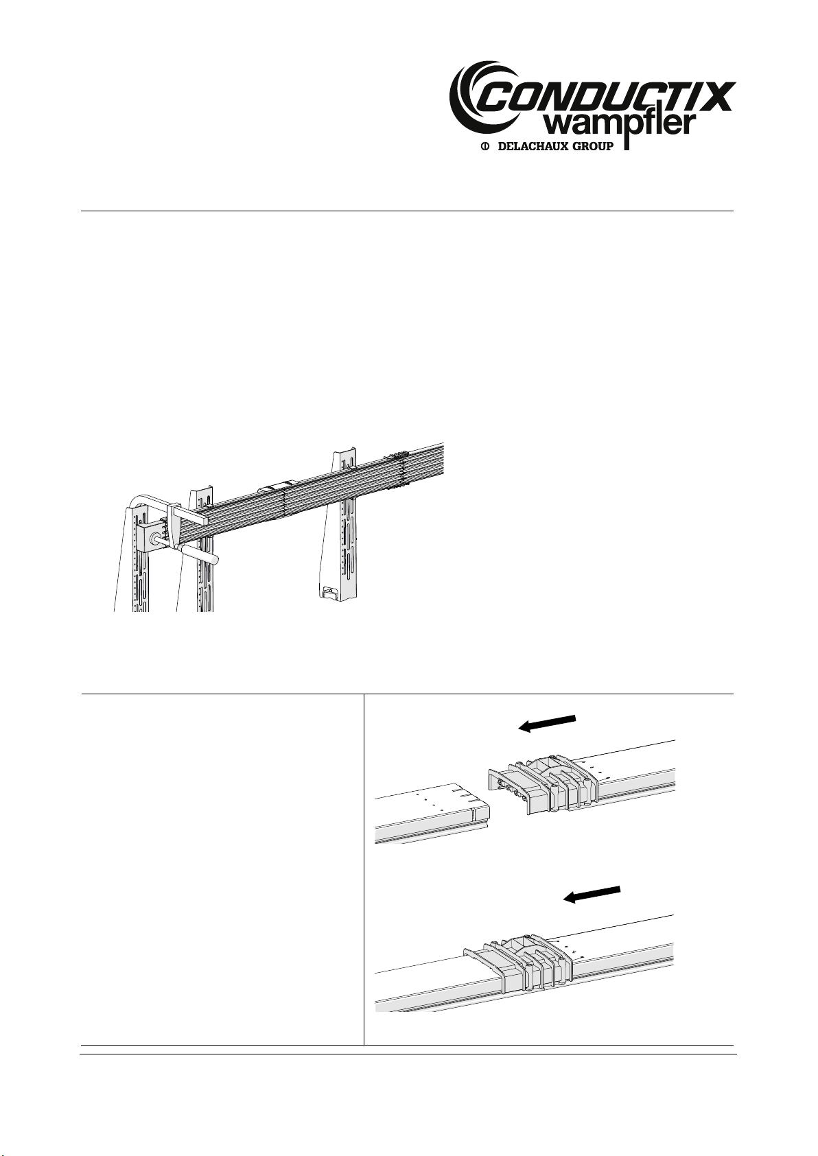
Install the mounting block (Order Number: 08-V015-0492-00x) in front of the conductor rail with a screw clamp (see Fig. 17).
The mounting block variant depends on the number of poles of the conductor rail. It might be necessary to mount a temporary
console to fasten the mounting block.
Fig. 17:Mounting block (Order Number: 08-V015-0492-00x) fasten with a screw clamp
Click the next conductor rail into the hanger clamp.
Establish the plug and socket connection:
Align the pin side in straight line at a distance of
approx. 50 mm with the fixed conductor rail.
Fix the connecting pins in straight line and
regularly at the sockets.
Push the pin side manually onto the fixed
conductor rail, so that all chamfered connecting
pins are introduced into the sockets of the fixed
conductor rail.
Fig. 18:Align conductor rail
Fig. 19:Insert the connecting pins into the sockets of the fixed conductor rail
Mounting Instructions
Multipole Conductor Rail System
Program 0831
MV0831-0006e-EN
www.conductix.com translated document Page 19 of 32
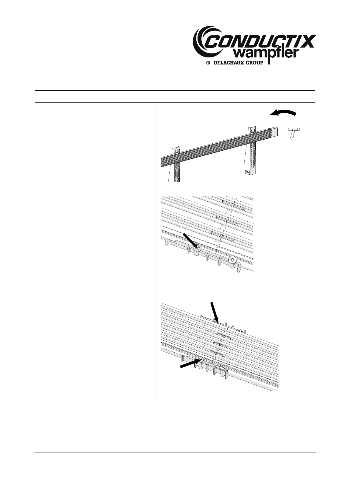
There are 2 different possibilities to make a plug
and socket connection:
1. Push the connector side manually over the open
rail end until it stops (see Fig. 15).
2. Place the mounting block next to the socket side
of the conductor rail to be mounted. Then force
the conductor rail carefully into the opposite
conductor rail by means of slight taps with a
soft-head hammer (see Fig. 20).
Control the correct position:
If the lateral cut-outs in the insulating profile match
with the screw holes in the connecting cap, you have
found the correct position (see Fig. 21).
Fig. 20:Force the conductor rail into its place by means of a soft-head hammer
Fig. 21:Correct position
Fix the connector cap and the insulating profile
with the 2 cross-head screws, as soon as the
conductor rail has been pushed on completely
(see Fig. 22).
Fig. 22:Fix the connector cap on both sides with cross-head screws.

Mounting Instructions
Multipole Conductor Rail System
Program 0831
MV0831-0006e-EN
www.conductix.com translated document Page 20 of 32
CAUTION!
A gap between the conductors is non-critical!
Conductor material and plastic profile have different coefficients of expansion. By pre-assembly the
conductor material is 2 mm shorter than the insulating profile (temperature 20°C), to compensate for
the expansion. Depending on the installation and operating temperature the gap can be up to 8 mm.
This gap is for physical reasons and does not have any influence on the multipole conductor rail
system.
Do not close the gap by a correction of the conductor position!
Mount all the other conductor rails, power feeds and expansion units in the same way.
Use the QR code („click“ or „scan“), to watch our animation
Power Feed Mounting
Check if the mounted length corresponds to the order-related length. If the installation was made too short, make it longer und
shorten the last conductor rail. See chapter 4.1 for further information.
Remove mounting block (see Fig. 17).
Depending on the position of the end and center feed, mount a power feed or end caps as a termination at the end of the
system.
WARNING!
Danger to life by electric shock and risk of injury at sharp edges!
In any case the terminations of the conductor rail must be protected against accidental contact by an
end or center feed or end caps!
Use the QR code („click“ or „scan“), to watch our animation
Conductor Rail Clipping and Connecting
Secure the end caps with the enclosed screws (2 pc.) (see Fig. 23).
Table of contents
Other Delachaux Industrial Equipment manuals


