Rev: 01.07.22 Page 10 CCD-0001459
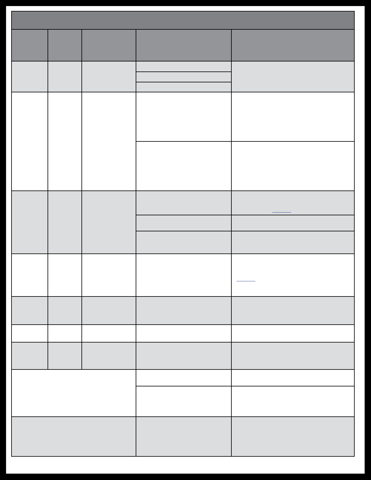
Fault Code Table - Programmable Controller 700155/700157
Fault
Code
(# of RED
flashes)
Fault
Type Description Why? What Should Be Done?
1 Major Stops not
programmed
Stops have not been set
Stops must be programmed by an
authorized service facility.
Stops were cleared
Stops were improperly set
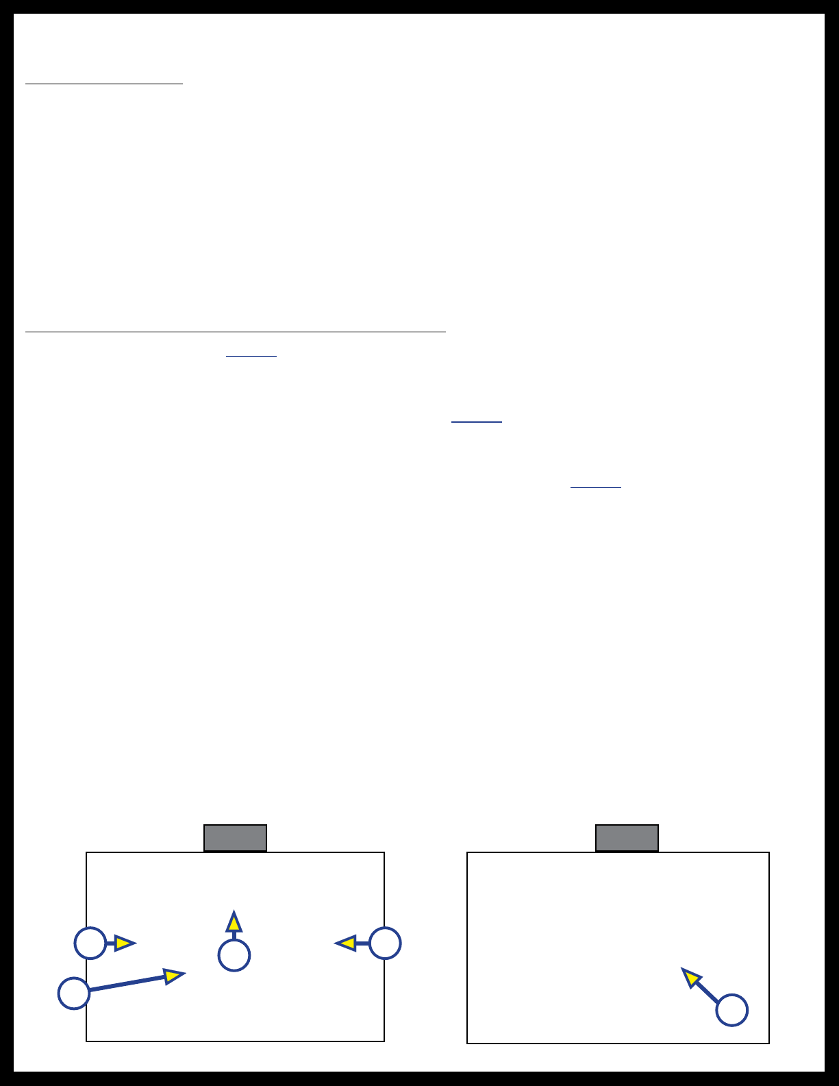
2 Minor System fault
Obstruction present
Run slide-out room in opposite direction of
drag. If slide-out room continues to move
in opposite direction, remove obstruction
or have damaged component replaced. If
slide-out room stops moving in opposite
direction, observe fault code and refer to
this chart.
Excessive system drag
Run slide-out room in opposite direction of
drag. If slide-out room continues to move
in opposite direction, remove obstruction
or have damaged component replaced. If
slide-out room stops moving in opposite
direction, observe fault code and refer to
this chart.
4 Major Motor fault
Bad or loose connection(s)
Check all connections at controller and
motor. See Wiring Diagram for Controller
1510000199 / 366697, 700155, 700157.
Defective harness Check harness for broken wires. Replace as
needed.
Open or shorted motor
Apply a 12V DC power source to the motor.
If motor does not operate, replace the
motor.
6 Minor Excessive
battery voltage
Supply voltage to controller is
17V DC or greater
Use a multimeter to check 2-pin power
connector at controller. See Wiring
Diagram for Controller 1510000199 /
366697, 700155, 700157. If the voltage is
17V DC or higher, contact OEM for power
and ground supplies.
7 Major Stops Not
Programmed
• Stops have not been set
• Stops were cleared
• Stops were improperly set
Stops need to be programmed according
to the programing instructions in this
document.
8 Minor Fuse, Motor 1 Motor fuse concern Contact Lippert Representative
9 Major Battery Drop
Out
Battery dropped below 8.5V
while extending or retracting
slide
Charge battery, start vehicle, generator, or
make sure unit is pugged into shore power.
Park brake LED flashing (700157 only)
Parking brake not set if
applicable Set parking brake if applicable
Ground signal lost at
park brake connector
on controller
Check for continuity to ground on wire
plugged into park brake connector at
controller. See Wiring Diagram.
Low voltage LED flashing Incoming voltage to controller
is below 12V DC
Use a multimeter to check 2-pin power
connector at controller. See Wiring
Diagram. If the voltage is below 12V DC,
contact OEM for recommendation.