Delavan SONAC 120 User manual
INSTALLATION & OPERATION MANUAL
SONAC/120 LIQUID LEVEL SWITCH
DECEMBER 2008 REV 1.0
1
An L&J Technologies Co.
5911 Buttereld Road
Hillside, IL 60162
Phone: 708-236-6000
Fax: 708-236-6006
INSTALLATION & OPERATION
MANUAL
SONAC 120
2
INSTALLATION & OPERATION MANUAL
SONAC/120 LIQUID LEVEL SWITCH
DECEMBER 2008 REV 1.0
was started in 1976 to offer new and innovative
electronic designs in tank gauging. L&J’s new products always used the
latest electronics and therefore the company quickly grew.
Ten years later L&J bought GPE. Along with GPE, L&J bought
, a GPE afliate that manufactures ttings and valves for
the same type of tanks that used the gauging equipment.
A short time later, all 3 companies were reorganized under one corporate
entity called . In 1994, a brand new, state-of-the-art
manufacturing facility was built to bring all of the L&J Technologies
manufacturing efforts under one roof.
In 1996, L&J bought , a manufacturer of liquid level controls
and Hi/Low level switches for the boiler, process, and liquid storage
industries.
On February 28, 2000, L&J purchased Durlam Associates, (now Durlam
Inc.). is located in Houston, Texas and is the leading
manufacturer of berglass reinforced plastic (FRP) Derakane 470
conservation vents and ttings.
On March 31, 2000, L&J purchased Delavan Process Instrumentation
in Naugatuck, CT. is a well-established name in
ultrasonic, capacitance and microwave point level and continuous level
measurement for liquids and solids. Delavan was relocated to L&J
Technologies corporate headquarters in Hillside, Illinois.
Today, the L&J family of companies is the world’s largest manufacturer
specializing in the monitoring, management, and control of bulk liquids.
L&J provides quality products for the Petroleum, Petrochemical,
Chemical, Food, Pharmaceutical, Pipeline, Steel, Water Treatment and
Biogas ( ) Industries.
Visit L&J Technologies on the internet at www.ljtechnologies.com

INSTALLATION & OPERATION MANUAL
SONAC/120 LIQUID LEVEL SWITCH
DECEMBER 2008 REV 1.0
3
TABLE OF CONTENTS
1.0 Introduction...................................................................................... 4
1.1 Description................................................................................ 4
1.2 Principle of Operation ............................................................... 4
1.3 Specications............................................................................ 4
2.0 Installation........................................................................................ 4
2.1 Unpacking................................................................................. 4
2.2 Mechanical Installation ............................................................. 4
2.3 Electrical Installation ................................................................. 7
3.0 Operation.......................................................................................... 7
3.1 General ..................................................................................... 7
3.2 Controls and Indicators/Calibration........................................... 7
3.3 Start-Up .................................................................................... 8
4.0 Maintenance & Service ...................................................................8
4.1 Product Warranty ........................................................................8

4
INSTALLATION & OPERATION MANUAL
SONAC/120 LIQUID LEVEL SWITCH
DECEMBER 2008 REV 1.0
1.0 INTRODUCTION
1.1 Description
This device is a single point, electronic switch for ON-
OFF level control of liquids, at temperatures from -65ºF
(-54ºC) to 400ºF (204ºC) and pressures to 4000 psi.
Typical applications include, crude and rened petroleum,
hot asphalt, solvents, chemicals, liqueed air fractions, LPG,
LNG, and most other liquids
1.2 Principle of Operation
The SONAC/120 Switch is comprised of a sensor,
interconnecting cable and electronic control unit.
The sensor is a magnetostrictive device consisting of a
diaphragm, nickel drive tube, bias magnet, drive coil and
pickup coil. The sensor diaphragm is electronically driven
to oscillate at its resonant frequency with a high-velocity, low
amplitude motion. When the product level covers the sensor,
the diaphragm is dampened. This produces a change in the
output signal level from the sensor’s pickup coil. The control
amplier, which is in a regenerative feedback loop circuit
with the sensor, processes the signal change, and actuates
the output relay for the desired end function.
SELF-TESTING FEATURE: A logic network is included
in the feedback loop to “prove” the mechanical and electrical
integrity of the sensing circuit. If an open or short circuit
occurs in the sensor connecting cable, or control amplier,
the relay immediately transfers to the alarm condition.
1.3 Specications
Supply Voltage Normal Absolute Limits
115 VAC 95-135 VAC
230 VAC 190-270 VAC
or 12-24 VAC
12-24 VDC
Frequency, AC Power 50-60 Hz 45 Hz Minimum
Time Delay Standard, 50 ms to
Adjustable 15 seconds
Failsafe Switch selectable, High
or Low Level
Environmental Rating NEMA 4X, IP55
Control Unit
Temperature Amplier -40 to 75ºC
Sensor Temperature, Temperature and pressure
Pressure Rating limits vary with sensor
model. Consult SONAC/120
data sheet for specication
information.
Sensor Mounting/ 1” NPTM
Process Connection
Distance-Sensor to Control 150 ft (45.7M with PVC
Unit, Maximum
Insulated Cable (BLUE)
100ft (30.5M) with TFE
Insulated (WHITE)
Indicators Two, light emitting diodes (LED).
RED - Illuminated when product is
present at sensor
YELLOW - Illuminated when relay is
energized
Output Relay, DPDT 2 Form C Contracts
5 A at 120 VAC Non-Inductive
3 A at 240 VAC Non-Inductive
3 A at 24 VDC Non-Inductive
Shipping Weight Control: 5 Pounds (2.5 Kilograms)
Sensor: 1.6 Pounds (.68) Kilograms
2.2 Mechanical
AMPLIFIER HOUSING
.875
(22.2)
2.00
(51)
6.000
(152.4)
1.062
(27)
8.625
(219)
2.00
(51)
3.00
(76.2)
9.375
(238)
1/2” Condult knockout
8.187
(208)
5.179
(131.5)
INSTALLATION DRAWING
NOTE: DIMENSIONS IN PARENTHESES DENOTE MILLIMETERS
2.0 INSTALLATION
2.1 Unpacking
Remove the system from the shipping carton and check the
nameplate model number against the packing list before
destroying any packing material. Remove plastic protective
closures from sensor

INSTALLATION & OPERATION MANUAL
SONAC/120 LIQUID LEVEL SWITCH
DECEMBER 2008 REV 1.0
5
SENSORS:
Basic installation dimensions for sensors are shown in gure
(1). Figure (2) shows a “Y” connection, gure (3) shows an
installation using conduit.
Mounting the sensor in the horizontal position is recommended.
If sensor must be mounted vertically (from top of tank or bin),
install the sensor at an angle (30º) to prevent entrapment
of air bubbles on the sensor face, which may cause false
responses.
1.9844
(50.4)
.875
(22.22)
1.50
(38.1)
2.500
(63.5)
Lanish, Tri-Clover
Tri-Clamp Type
16 amp (34) 1.5”
(38.1) pipe size
FIGURE 1
1-11 1/2 NPT
(25.4)
Stainless Steel
Sensor
625
(15.9)
1.3125
(33.3)
Cable Connector
.5625
(14.3)
Single Sensor, Sanitary Ladish Fitting
(USDA Approved for AAA Sanitary Service)
.5312
(13.5)
1.375
(35)
.875
(38.1)
1.50
(38.1)
1 NPT
(25.4) Hermetic Connetor
1.93
(49)
2.50
(63.5)
Single Sensor, Standard Hex Fitting
Verical Instal-
lation
1 NPT Fitting
(25.4)
Tank Wall
Installation for small
vessels or pipes.
1 NPT Fitting
(25.4)
Installation Suggestion
Sensor with
Conduit Attachment
Install sensor so sensor face is at least four inches away from
non-liquid surfaces, for pipe mounting, use “Y” connection.
Install the sensor so that the rear of the sensor, where the
cable attaches, is kept dry.
FIGURE 2
FIGURE 3
6
INSTALLATION & OPERATION MANUAL
SONAC/120 LIQUID LEVEL SWITCH
DECEMBER 2008 REV 1.0
CABLE ASSEMBLIES:
Cable Assemblies, (BLUE ) P/N 23276,77,78 are PVC
Insulated, and are rated for service from -65ºF to +220ºF
(-54ºC to +104ºC).
Cable Assemblies, (WHITE) P/N 23273,74,75 are
TFE Insulated, and are rated for continuous service at
temperatures from -425ºF - 225ºC cryogenic to +400ºF
(204ºC)
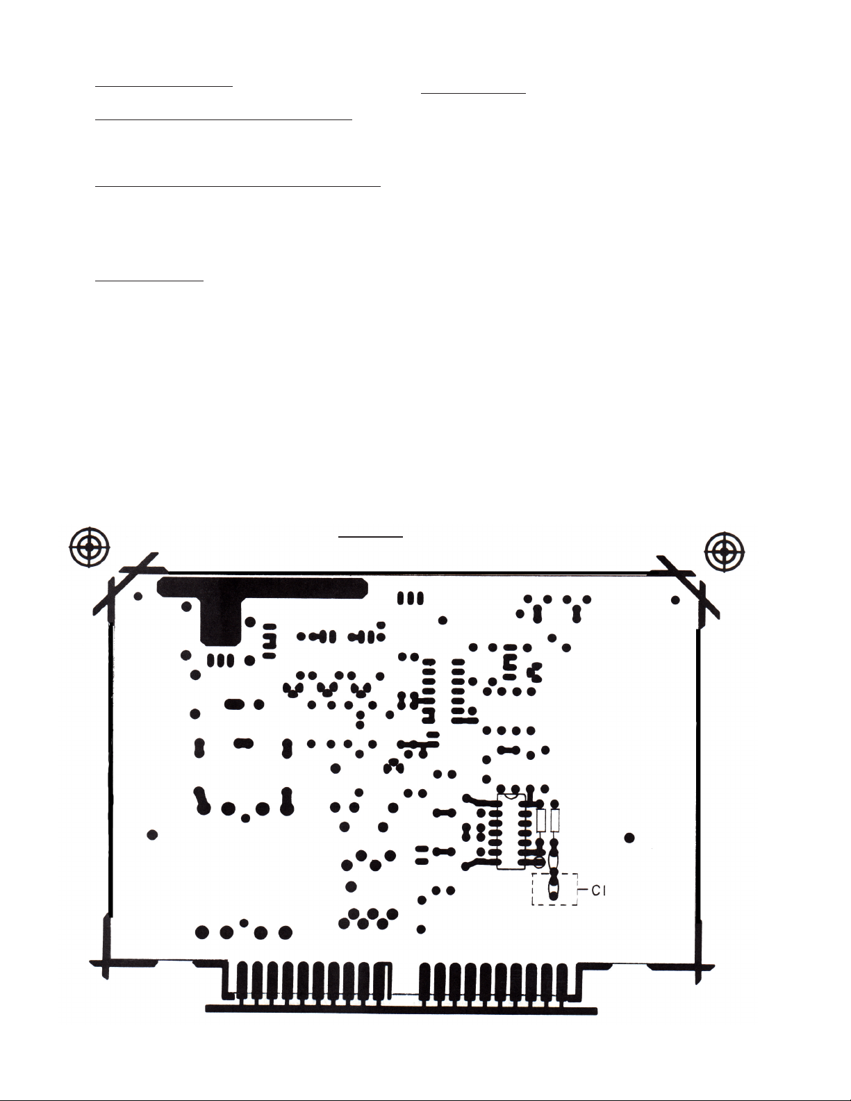
CABLE LENGTH:
The maximum permissible cable length varies with the
type of cable used. For PVC insulated cable (BLUE), the
length must not exceed 150 ft. or 45.7M. Blue cable length
over 75ft or 22.8m must have capacitor C1 removed (see
Figure 4). For TFE insulated cable (WHITE), the length
must not exceed 100ft. or 30.5M. White cable length
over 50ft or 15.2m must have capacitor C1 removed
(see gure 4). If a eld splice must be made, use ONLY
splicing techniques approved for shield cables.
CONTROL UNIT:
The electronic control unit was designed for eld mounting
in wet, corrosive environments. Good installation practice is
to mount the unit in an accessible location, as free as possible
from vibration, temperature extremes, and corrosive vapors,
where it is protected from mechanical damage and accessible
for calibration and service. In wet service areas, to prevent
moisture accumulation in the enclosure, conduits should enter
the enclosure from below.
Figure 4

INSTALLATION & OPERATION MANUAL
SONAC/120 LIQUID LEVEL SWITCH
DECEMBER 2008 REV 1.0
7
2.3 Electrical Installation
All electrical connections are made to the terminal strip in
the enclosure. Remove the cover, and the plug-in control
board, and wire the unit to power and control conduits in
accordance with applicable electrical codes. Refer to the
wiring diagram (2.3.1) for proper connections.
Do not substitute other cable for the special cable supplied by
DELAVAN for connection from the control unit to the sensor.
If the distance between the sensor and control exceeds the
stated cable length, consult the factory for specic installation
instructions.
DO NOT INSTALL, OR REMOVE THE PRINTED
CIRCUIT CARD WITH SYSTEM OR RELAY
CIRCUITS ENERGIZED, SERIOUS DAMAGE CAN
OCCUR TO CARD CONNECTIONS.
2.3.1 Terminal Designations:
Class I (Line Voltage) Terminals
1) Chassis Ground
2) Line Neutral
3) Line 115 VAC
4) Line 230 VAC
5) First set of Contacts N.C. (Power OFF)
6) Common
7) N.O.
8) Second set of Contacts N.C. (Power OFF)
9) Common
10) N.O.
Class II (Low Voltage) Terminals
11) Sensor (Black Lead)
12) Not Used
13) Sensor Shield (Bare Wire)
14) Not Used
15) Not Used
16) Low Voltage Input +24 v AC or DC
17) Low Voltage Input -
18) Not Used
19) Not Used
20) Sensor (White or Clear Lead)
3.0 OPERATION
3.1 General
3.2.1 Time Delay
A 20 turn potentiometer is furnished to adjust the time
delay between the sensor change of state (wet to dry
or dry to wet) and the relay actuation. The time delay
range is 50 milliseconds to approximately 15 seconds
maximum delay on and off.
3.2.2 Gain Control
A 20 turn potentiometer is furnished to match the
amplier gain with the sensor. CW rotation increases
the gain.
3.2.3 Liquid Level Indicator
A RED LED is illuminated when the product is pres-
ent at the sensor.
3.2.4 Relay Status Indicator
A YELLOW LED is illuminated when the relay is
energized.
3.2 Controls and Indicators
The Failsafe Switch determines the relay state when the
liquid is present. Failsafe high or failsafe low does not
indicate the physical location of the sensor installed in the
vessel.
This section contains the calibration and operational
information for the SONAC/120 Switch
3109
8
765
4
21 20
191817
1615
14
13
1211
ASSEMBLY NO: 42854
INSTR. MANUAL:
42858
RELAY CONTACTS
LOW
FAIL
SAFE
RELAY
FUNCTION
HIGH
FAIL
SAFE
SENSOR
STATUS
RELAY
STATUS
SONAC
NO
C
NC
NO
C
NC
230 VAC
115 VAC
GAIN
SENSOR
WHITE
LOW
VOLT
INPUT
SENSOR
SHIELD
TIME DELAY
SENSOR
BLACK

8
INSTALLATION & OPERATION MANUAL
SONAC/120 LIQUID LEVEL SWITCH
DECEMBER 2008 REV 1.0
3.3 Calibration
3.3.1 Set Time Delay Control 20 turns
clock-wise Gain Control 20 turns counter-
clockwise.
3.3.2 With the product level below the
sensor,(sensor is dry) apply power to the
control unit.
3.3.3 At this condition the RED LED should be
on and disregard the YELLOW LED.
3.3.4 Turn the Gain Control clockwise until the
RED LED just goes out (this will be the lower edge
of the window). Counting the turns, continue turning
the Gain Control clockwise until the RED LED just
come on again (this will be the upper edge of the
window).a
3.3.5 Now turn the Gain Control ½ of the amount
counterclockwise (this will be in the center of the
window). SEE BELOW
3.3.6 Set the Failsafe Switch to the position
required for your application. (See 3.2.1)
3.3.7 Set the Time Delay to the value required by
your process by rotating time delay control CCW.
NOTE: Time Delay Control Position.
Full Clockwise - Greater than 10 seconds.
Full Counter-Clockwise - Less then 100
milliseconds.
3.3.8 System is calibrated
4.0 MAINTENANCE & SERVICE
4.1 One-Year Product Warranty
DELAVAN PROCESS INSTRUMENTATION, control
products will be replaced, put in good operating condition,
or the purchase price refunded, at the option of DELAVAN,
free of charges except transportation, if defective in their
manufacture, labeling, packaging, or shipping, and if notice
of said defect is received by DELAVAN within one year from
the date of shipment. The cost of such replacement, repair
or refund of purchase price shall be the exclusive remedy
for any breach of any warranty, and DELAVAN shall not be
liable to any person for consequential damages for injury or
commercial loss resulting from any breach of any warranty.
DELAVAN make no warranty of tness for a particular
purpose, and makes no other warranty, express or implied,
including implied warranty arising from course of dealing
or usage of trade.
3.3.1
3.3.5 set point
3.3.4
red on
gain pot rotation CW
3.3.4
red on
red out

INSTALLATION & OPERATION MANUAL
SONAC/120 LIQUID LEVEL SWITCH
DECEMBER 2008 REV 1.0
9
Page intentionally left blank

10
INSTALLATION & OPERATION MANUAL
SONAC/120 LIQUID LEVEL SWITCH
DECEMBER 2008 REV 1.0
5911 Buttereld Rd.
Hillside, IL 60162
PH: (708) 236-6000
FAX: (708) 236-6006
E-MAIL: [email protected]
REACHING NEW LEVELS
IN
PROCESS MEASUREMENT
Table of contents
Popular Switch manuals by other brands


Brocade Communications Systems
Brocade Communications Systems VDX 6940 Series Hardware installation guide

HP
HP ProCurve 8100fl Installation and getting started guide

Cisco
Cisco RSP7000 Installation and configuration

Rontan
Rontan PALM SWITCH-S SC22 user guide

D-Link
D-Link DES-3528 - xStack Switch - Stackable Hardware installation guide

iPuray
iPuray BRT-706 quick start guide