manuals.online logo
Brands
  1. Home
  2. •
  3. Brands
  4. •
  5. Dell
  6. •
  7. Server
  8. •
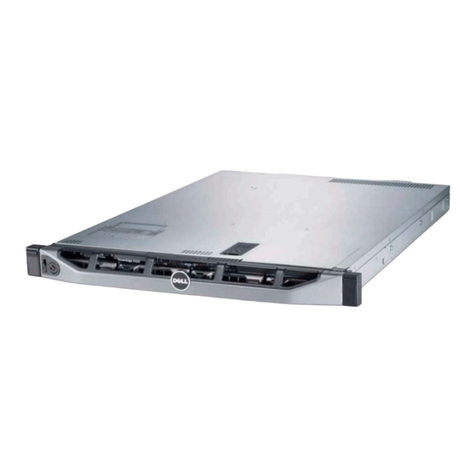
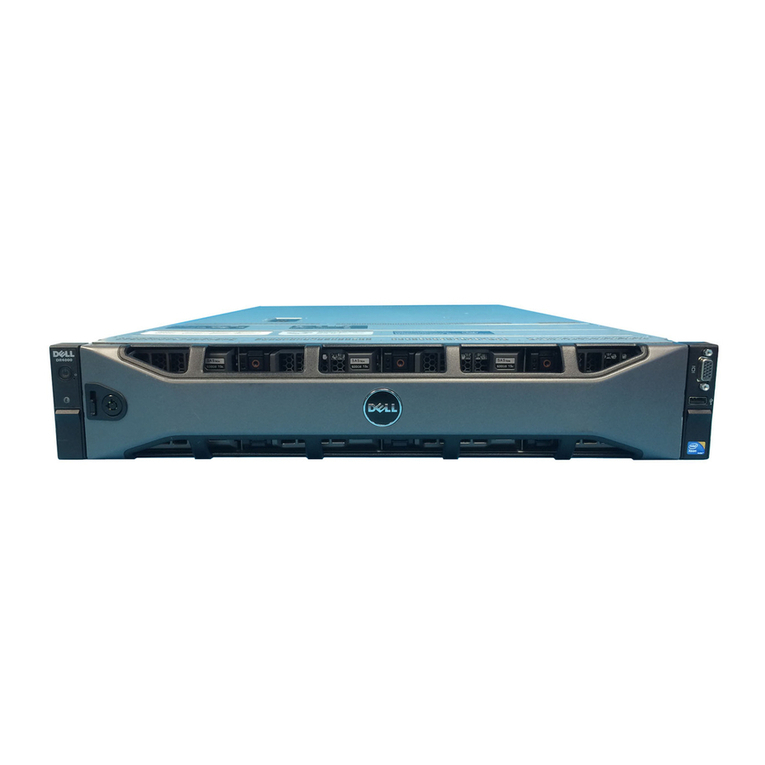
  9. Dell PowerEdge 2300 User manual

Dell PowerEdge 2300 User manual

ZZZGHOOFRP

'HOO

3RZHU(GJH

6\VWHPV
5$&.
,167$//$7,21*8,'(
:DUQLQJV&DXWLRQVDQG1RWHV
Throughout this document, there may be blocks of text printed in bold type or in italic
type. These blocks are warnings, cautions, and notes, and they are used as follows:
:$51,1*$:$51,1*LQGLFDWHVWKHSRWHQWLDOIRUERGLO\KDUPDQGWHOOV
\RXKRZWRDYRLGWKHSUREOHP
&$87,21$&$87,21LQGLFDWHVHLWKHUSRWHQWLDOGDPDJHWRKDUGZDUHRU
ORVVRIGDWDDQGWHOOV\RXKRZWRDYRLGWKHSUREOHP
NOTE: A NOTE indicates important information that helps you make better use of
your computer system.
____________________
Information in this document is subject to change without notice.
© 19971998 Dell Computer Corporation. All rights reserved.
Reproduction in any manner whatsoever without the written permission of Dell Computer Corpo-
ration is strictly forbidden.
Trademarks used in this text: Dell, the DELL logo, and PowerEdge are registered trademarks of
Dell Computer Corporation.
Other trademarks and trade names may be used in this document to refer to either the entities
claiming the marks and names or their products. Dell Computer Corporation disclaims any propri-
etary interest in trademarks and trade names other than its own.
May 1998 P/N 34368 Rev. A01
iii
&RQWHQWV
Before You Begin . . . . . . . . . . . . . . . . . . . . . . . . . . . . . . . . . . . . . . . . . . . . . . . . . . . . 3
Important Safety Informatio n . . . . . . . . . . . . . . . . . . . . . . . . . . . . . . . . . . . . . . . . 3
Kit Installation Restrictions . . . . . . . . . . . . . . . . . . . . . . . . . . . . . . . . . . . . . . 3
Rack Stabilizer Feet . . . . . . . . . . . . . . . . . . . . . . . . . . . . . . . . . . . . . . . . . . . . 3
Recommended Tools . . . . . . . . . . . . . . . . . . . . . . . . . . . . . . . . . . . . . . . . . . . . . . 3
Installing the Rack Kit . . . . . . . . . . . . . . . . . . . . . . . . . . . . . . . . . . . . . . . . . . . . . . . . . 4
Removing the Doors From the Rack . . . . . . . . . . . . . . . . . . . . . . . . . . . . . . . . . . 4
Installing the Slide Assemblies in the Rack . . . . . . . . . . . . . . . . . . . . . . . . . . . . . 6
Installing the PowerEdge 2300 System in the Rack . . . . . . . . . . . . . . . . . . . . . . . . . 10
Installing the Rails and Rack Adapters . . . . . . . . . . . . . . . . . . . . . . . . . . . . . . . . 10
Installing the Cable-Management Arm . . . . . . . . . . . . . . . . . . . . . . . . . . . . . . . . 14
Installing the Computer . . . . . . . . . . . . . . . . . . . . . . . . . . . . . . . . . . . . . . . . . . . 14
,QGH[
)LJXUHV Figure 1. Rack Kit Contents . . . . . . . . . . . . . . . . . . . . . . . . . . . . . . . . . . . . . . . . . 2
Figure 2. Opening the Latch on the Door . . . . . . . . . . . . . . . . . . . . . . . . . . . . . . . 4
Figure 3. Removing the Rack Doors . . . . . . . . . . . . . . . . . . . . . . . . . . . . . . . . . . . 5
Figure 4. Determining Where to Install the Slide Assemblies . . . . . . . . . . . . . . . 6
Figure 5. Installing a Cage Nut and Nut Plate . . . . . . . . . . . . . . . . . . . . . . . . . . . . 8
Figure 6. Installing the Slide Assemblies . . . . . . . . . . . . . . . . . . . . . . . . . . . . . . . 9
Figure 7. Computer Orientation . . . . . . . . . . . . . . . . . . . . . . . . . . . . . . . . . . . . . 11
Figure 8. Removing the Computers Top Cover . . . . . . . . . . . . . . . . . . . . . . . . . 12
Figure 9. Installing the Rack Adapter and Rail . . . . . . . . . . . . . . . . . . . . . . . . . . . 13
Figure 10. Installing the Cable-Management Arm . . . . . . . . . . . . . . . . . . . . . . . . 14
Figure 11. Installing the Computer in the Rack . . . . . . . . . . . . . . . . . . . . . . . . . . . 15
iv
Dell PowerEdge 2300 Systems Rack Installation Guide 1
'HOO3RZHU(GJH6\VWHPV
5DFN,QVWDOODWLRQ*XLGH
This installation guide provides instructions for trained service technicians i nstalling
one or more Dell PowerEdge 2300 systems in a Dell rack. One rack kit is required for
each PowerEdge system to be installed in the rack. The rack kit includes the following
items (see Figure 1):
One pair of slide assemblies with mounting bracket s
One computer top cover with attached rail and rack adapter
One rail
One rack adapter
One cable-management arm
Four curved nut plates
One cage-nut installation tool
Fourteen 10-32 pan-head Phillips-head screws
Seven 8-32 pan-head Phillips-head screws
Ten #10 flat metal washers
Six 10-32 cage nuts
NOTES: The nonmetric screws called out in illustrations and procedural steps are
identified first by size and then by the number of threads per inch. For example, a #10
Phillips-head screw with 32 threads per inch is identified as a 10-32 screw .
If you have purchased a Dell rack along with your PowerEdge 2300 system, the slide
assemblies are preinstalled in the rack.
2 Dell PowerEdge 2300 SystemsRack Installation Guide
)LJXUH5DFN.LW&RQWHQWV
FDJHQXW
LQVWDOODWLRQWRRO
QXWSODWH
FDEOHPDQDJHPHQWDUP
VOLGHDVVHPEOLHVSDLU
UDLO
UDFNDGDSWHU
FDJHQXW IODWPHWDOZDVKHU
[LQFKVFUHZ
FRPSXWHUFRYHUZLWKDWWDFKHG
UDLODQGUDFNDGDSWHU
[LQFKVFUHZ
Dell PowerEdge 2300 Systems Rack Installation Guide 3
%HIRUH<RX%HJLQ
Before you begin installing your PowerEdge 2300 system in the rack, carefully read
the safety precautions and tool requirements in the following subsections.
,PSRUWDQW6DIHW\,QIRUPDWLRQ
Follow these safety precautions when installing your computer in the rack .
.LW,QVWDOODWLRQ5HVWULFWLRQV
This rack kit is intended to be installed in a Dell rack by trained service technicians. If
you install the kit in any other rack, be sure that the rack meets the specifications of
the Dell rack.
:$51,1*'HOO·VVHUYHUV\VWHPVDUHFHUWLILHGDVFRPSRQHQWVIRUXVHLQ
'HOO·VUDFNFDELQHWXVLQJWKH'HOOFXVWRPHUUDFNNLW7KHILQDOLQVWDOODWLRQRI
'HOOVHUYHUVDQGUDFNNLWVLQDQ\RWKHUEUDQGRIUDFNFDELQHWKDVQRWEHHQ
DSSURYHGE\DQ\VDIHW\DJHQFLHV,WLVWKHFXVWRPHU·VUHVSRQVLELOLW\WRKDYH
WKHILQDOFRPELQDWLRQRI'HOOVHUYHUVDQGUDFNNLWVIRUXVHLQRWKHUEUDQGV
RIUDFNFDELQHWVHYDOXDWHGIRUVXLWDELOLW\E\DFHUWLILHGVDIHW\DJHQF\
5DFN6WDELOL]HU)HHW
:$51,1*,QVWDOOLQJ3RZHU(GJHV\VWHPVLQD'HOOUDFNZLWKRXWWKH
IURQWDQGVLGHVWDELOL]HUIHHWLQVWDOOHGFRXOGDOORZWKHUDFNWRWLSRYHU
SRWHQWLDOO\UHVXOWLQJLQERGLO\LQMXU\XQGHUFHUWDLQFLUFXPVWDQFHV7KHUH
IRUHDOZD\VLQVWDOOWKHVWDELOL]HUIHHWEHIRUHLQVWDOOLQJFRPSRQHQWVLQWKH
UDFN
The stabilizer feet help prevent the possibility of the rack tipping over when a Power-
Edge 2300 system is pulled out of the rack so that the slide assemblies are f ully
extended. Refer to the Dell PowerEdge Rack-Mountable Solutions Installation Guide
provided with the rack for instructions on installing the stabilizer feet.
:$51,1*$IWHULQVWDOOLQJFRPSXWHUVLQDUDFNQHYHUSXOOPRUHWKDQRQH
FRPSXWHURXWRIWKHUDFNRQLWVVOLGHDVVHPEOLHVDWRQHWLPH7KHZHLJKWRI
PRUHWKDQRQHH[WHQGHGFRPSXWHUFRXOGFDXVHWKHUDFNWRWLSRYHUDQG
LQMXUHVRPHRQH
5HFRPPHQGHG7RROV
To install the rack kit, you should have the following tools:
A #2 Phillips screwdriver
A flat-blade screwdriver
A 3/8-inch nut driver
The cage-nut installation tool included in the rack kit
A steel measuring tape
4 Dell PowerEdge 2300 SystemsRack Installation Guide
,QVWDOOLQJWKH5DFN.LW
NOTES: If you purchased a Dell rack along with your PowerEdge 2300 system, the
rack kit is preinstalled in the rack.
For instructions on installing the PowerEdge system itself, see Installing the Power-
Edge 2300 System in the Rack found later in this guide.
Use the following procedure to install the rack kit in the rack:
 5HPRYHWKHUDFN·VIURQWDQGEDFNGRRUV
 ,QVWDOOWKHVOLGHDVVHPEOLHVLQWKHUDFN
The subsections that follow include instructions for performing these tasks.
5HPRYLQJWKH'RRUV)URPWKH5DFN
You must remove the doors from the rack to provide access to the interior of the rack
and to prevent damage to the doors while installing the kit. Use the following proce-
dure to remove the doors.
:$51,1*7RSUHYHQWSHUVRQDOLQMXU\GXHWRWKHVL]HDQGZHLJKWRIWKH
GRRUVQHYHUDWWHPSWWRUHPRYHWKHGRRUVE\\RXUVHOI
 2SHQWKHODWFKRQWKHIURQWGRRUVHH)LJXUH
Slide the latchs push button cover up as far as it will go, press the pus h button,
rotate the handle clockwise until the latch releases, and then pull the door open .

)LJXUH2SHQLQJWKH/DWFKRQWKH'RRU
pushbutton
button cover
handle
Dell PowerEdge 2300 Systems Rack Installation Guide 5
 5HPRYHWKHIURQWGRRUDVVKRZQLQ)LJXUH
a. One person should grasp the top of the door to stabilize it. The other person
should grasp the bottom of the door.
b. The person holding the bottom of the door should press the release lever on
the bottom hinge and then pull the bottom of the door away from the rack a
few inches.
c. The person holding the top of the door should press the release lever on the
top hinge and then pull the door away from the rack.
)LJXUH5HPRYLQJWKH5DFN'RRUV
 5HSHDWVWHSVDQGWRUHPRYHWKHEDFNGRRUIURPWKHUDFN
Store the two doors where they will not injure someone if they accidently fall over.
hinge
release
lever
6 Dell PowerEdge 2300 SystemsRack Installation Guide
,QVWDOOLQJWKH6OLGH$VVHPEOLHVLQWKH5DFN
Use the following procedure to install the slide assemblies in the rack:
 'HWHUPLQHZKHUH\RXZDQWWRLQVWDOOWKHVOLGHDVVHPEOLHV
:$51,1*,I\RXDUHLQVWDOOLQJPRUHWKDQRQHFRPSXWHULQVWDOOWKH
VOLGHDVVHPEOLHVVRWKDWWKHILUVWFRPSXWHULVLQVWDOOHGLQWKHORZHVW
SRVLWLRQLQWKHUDFN
If you intend to install more than one PowerEdge 2300 system in the rack, you
must install the slide assemblies so that there is 10.5 inches (6U) of vertical
space between the top of one slide assembly and the top of the next (see
Figure 4). In the Dell rack, the rails of the rack are marked by small indentations in
1U (1.75-inch) increments. To install the computer in the racks lowest position,
locate the cage nuts 6U (10.5 inches) f rom the bottom of each vertical rail . After
determining where to install the slide assemblies, mark the locations of the cage
nuts on the racks vertical rails with a felt-tipped marker or masking tape.
)LJXUH'HWHUPLQLQJ:KHUHWR,QVWDOOWKH6OLGH$VVHPEOLHV
cage nut
vertical rail
10.5 inches
10.5 inches
6U (10.5 inches) between
slide assemblies (drawing
is not to scale)
#10-32 x 0.5-inch screw
nut plate
Dell PowerEdge 2300 Systems Rack Installation Guide 7
 ,QVWDOOWKHFDJHQXWVDQGQXWSODWHV
Install the curved nut plates on the vertical rails where you want the ends of the
slide assemblies to be located (see Figure 5). Each curved nut plate is held in
place by one Phillips-head screw and one cage nut.
The following substeps explain how to install the cage nuts and the nut plates:
a. Insert the lower lip of the 10-32 cage nut over the bottom of the opening in
the back of a rail as shown in step 1 in Figure 5. Then insert the small end of
the cage-nut installation tool through the opening in the rail (from the front),
and hook the tool over the top lip of the cage nut.
b. Push in on the cage nut while rotating the tool up and pulling the tool back
toward you until the top lip of the cage nut snaps into position (see step 1 in
Figure 5).
c. Repeat this process to install the remaining cage nuts.
d. To install one of the curved nut plates, insert it through the hole below the
cage nut (from the back of the rail) as shown in step 2 in Figure 5. Then
secure the nut plate in place with a 10-32 x 0.5-inch Phillips-head screw ( see
step 3 in Figure 5).
e. Repeat substeps a through d to install the remaining nut plates.
8 Dell PowerEdge 2300 SystemsRack Installation Guide

)LJXUH,QVWDOOLQJD&DJH1XWDQG1XW3ODWH
 8VLQJD3KLOOLSVVFUHZGULYHUVOLJKWO\ORRVHQWKHVOLGHDOLJQPHQWVFUHZ
WKDWKROGVWKHIURQWVOLGHPRXQWLQJEUDFNHWWRWKHH[WHULRUVOLGHVHH
)LJXUH
NOTE: Do not adjust the back slide-mounting brackets. Doing so will prevent the
computer from aligning properly with the rack. Make adjustments only to the
front slide-mounting brackets .
cage nut
nut plate
10-32 x 0.5-inch
screw



cage-nut
installation tool
Dell PowerEdge 2300 Systems Rack Installation Guide 9

)LJXUH,QVWDOOLQJWKH6OLGH$VVHPEOLHV
 ,QVWDOOWKHVOLGHDVVHPEOLHVLQWKHUDFN
NOTES: When installing the slide assemblies, be sure that the green plastic
stops at the ends of the channels are at the back of the rack and that the green
push button (on the interior slide) is near the front of the rack (see Figure 11).
If the slide assembly is completely extended and locked in position, press the
spring located on the inside of the interior slide (near the end with the green plas-
tic stop) to release the slide so that it can be returned to the retracted position.
a. Insert the slides mounting-bracket flange between the nut plate and the
racks vertical rail as shown in Figure 6.
QXWSODWH
PRXQWLQJEUDFNHWIODQJH
[LQFKVFUHZV
YHUWLFDOUDLO
VOLGHDOLJQPHQWVFUHZ
IURQWRIUDFN
IODWPHWDOZDVKHUV
cage nut
8.25 inches
10 Dell PowerEdge 2300 SystemsRack Installation Guide
b. Position the mounting bracket at the back of the slide assembly so that its
two slots are aligned with the two lowest holes in the nut plate (see Fig -
ure 6). Secure the mounting bracket with two 10-32 x 0.5-inc h Phillips-head
screws and two #10 flat metal washers. Do not completely tighten the two
mounting screws until you install the computer and verify that the width
between the slide assemblies is correct.
c. Position the mounting bracket at the front of the slide assembly so that its
two slots are aligned with the two lowest holes in the nut plate . Secure the
mounting bracket using two 10-32 x 0.5-inch Phillips-head screws and two
#10 flat metal washers .
d. If necessary, adjust the slide assemblys length until the mounting-bracket
flange fits snugly against the back of the rails on both ends . (Dell racks
require no adjustment to the slide assemblies; the slide assemblies a re pre-
configured to the correct length).
e. Tighten the slide alignment screw you loosened in step 3.
 5HSHDWVWHSVWKURXJKWRLQVWDOOWKHVHFRQGVOLGHDVVHPEO\
 ,QVWDOORQHFDJHQXWLQHDFKIURQWYHUWLFDOUDLOIRUWKHUDFNDGDSWHU
WKXPEVFUHZVVHH)LJXUH
Locate the cage nuts 8.25 inches below the cage nuts you installed in step 2 .
,QVWDOOLQJWKH3RZHU(GJH6\VWHPLQ
WKH5DFN
The subsections that follow include instructions for installing a PowerEdge 2300 sys-
tem in the rack.
,QVWDOOLQJWKH5DLOVDQG5DFN$GDSWHUV
Use the following procedure to install the rails and rack adapters on the computer:
 5HPRYHWKHOHIWDQGULJKWVLGHFRPSXWHUFRYHUV
See Chapter 7, Checking Inside the Computer, in the computers Installation
and Troubleshooting Guide for instructions on removing the computer covers.
Dell PowerEdge 2300 Systems Rack Installation Guide 11
 5HPRYHWKHIHHWIURPWKHFRPSXWHU
:$51,1*7KHFRPSXWHUZHLJKVDSSUR[LPDWHO\NJOEZKHQ
IXOO\ORDGHG7RSUHYHQWSHUVRQDOLQMXU\GRQRWDWWHPSWWRPRYHWKH
FRPSXWHUE\\RXUVHOI
a. Lay the computer on its left side (see Figure 7) on a piece of foam or card-
board (to prevent damage to the computer) while you remove the feet.
)LJXUH&RPSXWHU2ULHQWDWLRQ
b. Using a small flat-blade screwdriver, unscrew the plastic rivet securing each
foot.
c. From outside of the chassis, pull each foot from the chassis.
 5HPRYHWKHFRPSXWHU·VWRSFRYHU
a. Remove the two screws at the front edge of the top cover (see Figure 8).
(Retain the screws for later use.)
b. Slide the top cover about a half inch toward the front of the computer and lift
it away.
back of computer
right sideleft side
front of computer
12 Dell PowerEdge 2300 SystemsRack Installation Guide
)LJXUH5HPRYLQJWKH&RPSXWHU·V7RS&RYHU
 5HSODFHWKHWRSFRYHUZLWKWKHQHZWRSFRYHUUDLODVVHPEO\VXSSOLHGLQ
WKHUDFNNLW
Use the two screws that you removed in step 3 to secure the new top cover.
 5HSODFHWKHFRPSXWHU·VVLGHFRYHUVDQGIURQWEH]HO
When replacing the side covers, install the cover with the system label on the
right side of the computer
See Chapter 7, Checking Inside the Computer, in the Installation and Trouble-
shooting Guide for instructions on replacing the computer cover s and front bezel.
 ,QVWDOOWKHUDLORQWKHFRPSXWHUVHH)LJXUH
Orient the rail such that the three holes near the back of the rail are near the back
of the computer. Attach the rail with three 8-32 x 0.313-inch Phillips-head screws.
VFUHZV
WRSFRYHU
VLGHFRYHUV
Dell PowerEdge 2300 Systems Rack Installation Guide 13
)LJXUH,QVWDOOLQJWKH5DFN$GDSWHUDQG5DLO
 ,QVWDOOWKHUDFNDGDSWHURQWKHFRPSXWHUVHH)LJXUH
Secure the adapter to the computer with two 8-32 x 0.313-inch Phillips-head
screws.
UDFNDGDSWHU
[LQFKVFUHZV
UDLO
14 Dell PowerEdge 2300 SystemsRack Installation Guide
,QVWDOOLQJWKH&DEOH0DQDJHPHQW$UP
To install the cable-management arm on the computer, align the bracket on the end of
the arm with the corresponding holes on the computer s back panel (see Figure 10).
Secure the arm using two 8-32 x 0.313 Phillips-head screws.
)LJXUH,QVWDOOLQJWKH&DEOH0DQDJHPHQW$UP
,QVWDOOLQJWKH&RPSXWHU
Use the following procedure to install the computer in the rack.
:$51,1*,I\RXDUHLQVWDOOLQJPRUHWKDQRQHFRPSXWHULQVWDOOWKHILUVW
FRPSXWHULQWKHORZHVWSRVLWLRQLQWKHUDFN1HYHUSXOOPRUHWKDQRQHFRP
SXWHURXWRIWKHUDFNDWDWLPH
 3XOOWKHWZRLQWHULRUVOLGHVRXWRIWKHUDFNXQWLOWKH\ORFNLQWKH
H[WHQGHGSRVLWLRQ
 /LIWWKHFRPSXWHULQWRSRVLWLRQDQGLQVHUWWKHFRPSXWHU·VUDLOVLQWRWKH
FKDQQHOVRIWKHLQWHULRUVOLGHVVHH)LJXUH
:$51,1*'XHWRWKHVL]HDQGZHLJKWRIWKHFRPSXWHUQHYHUDWWHPSW
WRLQVWDOOWKHFRPSXWHULQWKHVOLGHDVVHPEOLHVE\\RXUVHOI
FDEOHPDQDJHPHQWDUP
[LQFKVFUHZ
V


EDFNRIFRPSXWHU
IODWPHWDOZDVKHU
V

YHUWLFDOUDLO

[

LQFKVFUHZ
V


Dell PowerEdge 2300 Systems Rack Installation Guide 15
The slotted holes in the slide-mounting brackets allow for adjustment if the width
between the slide assemblies is not correct. Adjust the width so that the com-
puter slides easily into place.
NOTE: As you push the computer into the interior slides, the slide assemblies
lock in the extended position. Press the green push button near the end of each
interior slide to release the locks (see Figure 11), and then slide the computer
completely into the rack.
)LJXUH,QVWDOOLQJWKH&RPSXWHULQWKH5DFN
 7LJKWHQDOORIWKHVOLGHDVVHPEO\PRXQWLQJVFUHZVVHFXUHO\
After you tighten all of the mounting-bracket screws, slide the computer in and
out a few times to ensure that none of the adjustments changed as you tight-
ened the screws.
LQWHULRUVOLGH
JUHHQSXVKEXWWRQV
16 Dell PowerEdge 2300 SystemsRack Installation Guide
 6OLGHWKHFRPSXWHUFRPSOHWHO\LQWRWKHUDFNDQGWLJKWHQWKHIRXU
WKXPEVFUHZVWRKROGWKHFRPSXWHULQSRVLWLRQ
 6HFXUHWKHORRVHHQGRIWKHFDEOHPDQDJHPHQWDUPWRWKHEDFNYHUWL
FDOUDLODVVKRZQLQ)LJXUH
Use two 10-32 x 0.5-inch Phillips-head screws and two #10 flat metal washers to
secure the cable-management arm to the back vertical rail as shown in Figure 10.
(This is the rail on the right as you face the back of the rack.) Make sure that the
cable-management arm is straight in relation to the computerthat is, parallel to
the ground.
 ,QVWDOOWKHFDEOHV
Connect the cables to the computer. For details, see the computer systems
Installation and Troubleshooting Guide and Users Guide.
 6HFXUHWKHFDEOHV
After connecting the cables to the computer, route the cables along the cable-
management arm, and secure the cables to the cable-management arm with the
Velcro strips attached to the cable-management arm.
 6OLGHWKHFRPSXWHULQDQGRXWRIWKHUDFNWRYHULI\WKDWWKHFDEOHVDUH
URXWHGFRUUHFWO\
Make sure that the cables are not pinched in the cable-management arm joints.
NOTES: You will feel resistance as the rails thread themselves into the ball-bear-
ing cages in the slide assembliesthis resistance is normal. Continue to push
the computer inward until it slides completely into the rack and is fully seated.
(You may have to pull the computer partially out and push it back into the rack to
fully thread the ball-bearing cages.) When fully engaged, the back of the four cap-
tive thumbscrews should mate with the cage nuts on the racks front vertical
rails.
As you pull the computer out to its furthest extension, the slide assemblies will
lock in the extended position. To push the computer back into the rack, press the
green buttons near the front of both interior slides (see Figure 10) and simulta-
neously push in on the computer.

Other manuals for PowerEdge 2300

7

Other Dell Server manuals

Dell PowerEdge C6320 User manual

Dell

Dell PowerEdge C6320 User manual

Dell 5J5D0 Manual

Dell

Dell 5J5D0 Manual

Dell PowerEdge R920 User manual

Dell

Dell PowerEdge R920 User manual

Dell PowerEdge R910 User manual

Dell

Dell PowerEdge R910 User manual

Dell EMC PowerEdge XR11 Manual

Dell

Dell EMC PowerEdge XR11 Manual

Dell Vostro 1400 Assembly instructions

Dell

Dell Vostro 1400 Assembly instructions

Dell External OEMR XL R720XD Quick start guide

Dell

Dell External OEMR XL R720XD Quick start guide

Dell PowerEdge R840 User manual

Dell

Dell PowerEdge R840 User manual

Dell PowerEdge 1955 User manual

Dell

Dell PowerEdge 1955 User manual

Dell FC4500 Application guide

Dell

Dell FC4500 Application guide

Dell PowerEdge C8000 User manual

Dell

Dell PowerEdge C8000 User manual

Dell Wyse ThinOS T10 User manual

Dell

Dell Wyse ThinOS T10 User manual

Dell PowerEdge M520 User manual

Dell

Dell PowerEdge M520 User manual

Dell EMC E39S Series Manual

Dell

Dell EMC E39S Series Manual

Dell PowerEdge 2420 User manual

Dell

Dell PowerEdge 2420 User manual

Dell 810 User manual

Dell

Dell 810 User manual

Dell PowerEdge C6145 Quick start guide

Dell

Dell PowerEdge C6145 Quick start guide

Dell EMC VxFlex Ready Node 13G Manual

Dell

Dell EMC VxFlex Ready Node 13G Manual

Dell PowerEdge 4600 User manual

Dell

Dell PowerEdge 4600 User manual

Dell PowerEdge 1400SC Operator's manual

Dell

Dell PowerEdge 1400SC Operator's manual

Dell PowerEdge R410 User manual

Dell

Dell PowerEdge R410 User manual

Dell PowerEdge C6220 User manual

Dell

Dell PowerEdge C6220 User manual

Dell PowerEdge C6220 II User manual

Dell

Dell PowerEdge C6220 II User manual

Dell External OEMR R620 User manual

Dell

Dell External OEMR R620 User manual

Popular Server manuals by other brands

BITMAIN ANTMINER S19a installation guide

BITMAIN

BITMAIN ANTMINER S19a installation guide

Silicon Graphics Origin 3900 user guide

Silicon Graphics

Silicon Graphics Origin 3900 user guide

Oracle ORACLE9I B10508-01 Application guide

Oracle

Oracle ORACLE9I B10508-01 Application guide

HP NetServer LH 3r Installation road map

HP

HP NetServer LH 3r Installation road map

HP Proliant DL580 Quickspecs

HP

HP Proliant DL580 Quickspecs

TYAN TN70A-B8026 Service engineer's manual

TYAN

TYAN TN70A-B8026 Service engineer's manual

Supero SuperServer 5015A-PHF user manual

Supero

Supero SuperServer 5015A-PHF user manual

Lenovo ThinkServer RD120 Kullanma kılavuzu

Lenovo

Lenovo ThinkServer RD120 Kullanma kılavuzu

TYAN Transport GX21 B2735 user manual

TYAN

TYAN Transport GX21 B2735 user manual

Fujitsu SPARC Enterprise M3000 Product notes

Fujitsu

Fujitsu SPARC Enterprise M3000 Product notes

Compaq t1000 - Terminal Thin Client PC manual

Compaq

Compaq t1000 - Terminal Thin Client PC manual

Exsys EX-6002PoE quick start guide

Exsys

Exsys EX-6002PoE quick start guide

Intel SR1530AHNA Technical product specification

Intel

Intel SR1530AHNA Technical product specification

Lenovo ThinkServer TD230 manual

Lenovo

Lenovo ThinkServer TD230 manual

Moxa Technologies NPort 5600 Series Quick installation guide

Moxa Technologies

Moxa Technologies NPort 5600 Series Quick installation guide

Acer Altos G700 series user guide

Acer

Acer Altos G700 series user guide

Digital Watchdog DW-BJP1U-LX quick start guide

Digital Watchdog

Digital Watchdog DW-BJP1U-LX quick start guide

Supermicro SuperStorageSystem SSG-5019D8-TR12P user manual

Supermicro

Supermicro SuperStorageSystem SSG-5019D8-TR12P user manual

manuals.online logo
manuals.online logoBrands
  • About & Mission
  • Contact us
  • Privacy Policy
  • Terms and Conditions

Copyright 2025 Manuals.Online. All Rights Reserved.