Dellmeco DM 08/10 User manual

Serial no.
INSTRUCTION MANUAL
Air operated double diaphragm pumps
Ver. 1.26
Models: DM
08/10
DM 10/25
DM 15/55
DM 25/125
DM 40/315
DM 50/565
DM 80/850

2 I DELLMECO I AODD DIAPHRAGM PUMPS
DECLARATION OF CONFORMITY
Directive
2006/42/EC
, Annex 2A
Company: DELLMECO LTD
Address: Unit 1, Willow Row
Longton, Stoke on Trent
Staffordshire, ST3 2PU, United Kingdom
declares under our sole responsibility, that the product:
Product name: Air Operated Double Diaphragm Pumps
Models: DM - series
Referred to in this declaration conforms with the:
- Directive 2006/42/EC
Date: July 1
st
2014
K. Ziemann
Managing Director

3I DELLMECO I AODD DIAPHRAGM PUMPS
Tableofcontents
1.Introduction_________________________________________________________________________________ 4
2. For safe operation____________________________________________________________________________ 4
3. Warnings and cautions________________________________________________________________________ 4
4. Operating caution ____________________________________________________________________________ 4
5. Names of parts and materials__________________________________________________________________ 6
5.1. DM 08/10, DM 10/25 ______________________________________________________________________ 6
5.2. DM 15/55, DM 25/125 _____________________________________________________________________ 8
5.3. DM 40/315, DM 50/565 ___________________________________________________________________ 10
5.4. DM 80/850______________________________________________________________________________ 12
6.Assembly __________________________________________________________________________________ 14
7. Installation_________________________________________________________________________________ 14
7.1.Installing the pump ________________________________________________________________________ 14
7.2. Connecting the ground wire_________________________________________________________________ 16
8.Connection _________________________________________________________________________________ 16
8.1. Connecting fluid piping____________________________________________________________________ 16
8.2. Connecting air piping______________________________________________________________________ 17
9.Operation__________________________________________________________________________________ 18
9.1. Method of operation_______________________________________________________________________ 18
9.2. Flow adjustment__________________________________________________________________________ 18
9.3. Shutdown _______________________________________________________________________________ 19
10.Method of cleaning _________________________________________________________________________ 19
11.Dailycheck_________________________________________________________________________________ 20
12.Possible problems___________________________________________________________________________ 20
13.Returning the product for servicing ___________________________________________________________ 22
14.Main body specification _____________________________________________________________________ 24
14.1. Main specification ________________________________________________________________________ 24
14.2. Appearance and dimensions_________________________________________________________________ 24
14.3. Technical Data___________________________________________________________________________ 25
14.4. Pump code______________________________________________________________________________ 25
14.5. Performance curves _______________________________________________________________________ 26
15. Dellmeco Active Pulsation Dampers for Plastic Pumps____________________________________________ 27
15.1. Main specification________________________________________________________________________ 27
15.2. Appearance and dimensions (pump with pulsation damper) _________________________________________ 30
15.3. Discharge port for pulsation damper assembly ___________________________________________________ 30
16. Optional Equipment________________________________________________________________________ 31
16.1. Barrier Chamber System (option code BC1, BC2, BC3)____________________________________________ 31
16.2. Stroke Counting (option code SC1, SC2, SC3, SC5, SC6) __________________________________________ 33
16.3. Diaphragm Monitoring (option code DM1, DM2) ________________________________________________ 35
16.4. Flange Connections (option code F1, F2, F3, F4, F7, F8, F9) ________________________________________ 35
16.5. Sleeve with Split Connections (option code S) ___________________________________________________ 36
16.6 Back Flushing System (option code BF1, BF2, BF4, BF5) ________________________________________ 36
16.7 High Pressure System (option code HP)_______________________________________________________ 38
17.Limited warranty___________________________________________________________________________ 40

4 I DELLMECO I AODD DIAPHRAGM PUMPS
1. Introduction
This pump is a positive-displacement pump that transfers fluids by means of diaphragms movement operated by
compressed air. The casing in contact with the fluid is made of PE (polyethylene), PE conductive, PTFE
(polytetrafluoroethylene), PTFE conductive.
2. For safe operation
This document contains information indispensable for maintaining safe and efficient operation of this product.
Read this document carefully before using the pump, particularly the "Warnings and cautions". Get familiar with all
operating procedures. This document must be kept handy for future reference.
3. Warnings and cautions
The meanings of warning and caution symbols are given below. Be sure to remember their meanings.
WARNING
:
ignoring the warning and operating the product in an improper manner can result
in danger of serious bodily injury or death.
CAUTION
:ignoring the warning and operating the product in an improper manner can result
in danger of personal injury or property damage.
ØThis symbol means a “DON’T”, and will be followed by an explanation on what you must not do.
!
!!
!This symbol means a “DO”, and will be followed by an explanation on what you must do in a specified situation.
4. Operating caution
Before using this product
!
!!
!
WARNING
!
!!
!
!
!!
!
!
!!
!Todrive thepumpyoumustuse oneofthe followingcompressedgases(calledinthis document "compressedair"):
-Compressed air supplied from air compressor
- Nitrogen(N
2
)gas
Useofcompressedairotherthan theabovemay cause airpollution,damagetothepump,orevenanexplosion.
!
!!
!The maximumpermissiblepressureforthecompressedair, and thefluidpumpedbyoneofits pumpsis8bars.
Shouldtheaboveapplicablemaximum permissiblepressurebeexceeded,thefollowingresultsmayfollow:
damage to the casing, or even a severe, possibly fatal accident.
In some pomp executions, specified by manufacturer, the max. pressure can reach 14 bars.
!
!!
!In case a diaphragm gets damaged, fluid willgush outtogether with air through the exhaust port. Provide
protective measures in consideration of possible leakage of fluid.
Whenusingthe hoseandpitetc,makesuretousea modelwithappropriatecorrosionresistancefor thefluid tobe
pumped.

5I DELLMECO I AODD DIAPHRAGM PUMPS
!
!!
!
WARNING
!
!!
!
CAUTION
!
!!
!
When installing this product, be sure to connect a ground wire from the specified position of this product.
Otherwise friction between parts and abrasion caused by the flow of some fluids inside the casing may
generate static electricity. Depending on the type of fluid being pumped and the installation environment
(such as gases in the air and type of surrounding mixtures), static electricity could cause fire or electric
shock.
!
!!
!Some fluid may remain inside the pump and inside the connected piping after shutting down the pump, or if
the pump is left unused for a prolonged period.
Therefore, be sure to purge the system of fluid and clean the pump before prolonged disuse.
The fluid remaining in the connected piping as well as the pump itself may expand because of freezing or
heat which may cause damage to the pump or/and piping and lead to leakage of the fluid.
Ø
Use only genuine Dellmeco parts when replacing component parts of this product.
!
!!
!Torque of all tightening parts must be checked before running the pump. Designated torques are mentioned
in maintenance manual.
!
!!
!In case of pumping a hazardous fluid (hot, flammable, strong acid, etc.) with this pump, protective measures
(install a pit, a protection box, sensors, etc.) must be provided in consideration of possible leakage of fluid.
Warning signs must be displayed at necessary places. Leakage of fluid may cause fire or accident.
!
!!
!Before using this pump, get fully familiar with the precautions regarding the fluid to be pumped, and verify
the corrosion resistance of the parts that will come into contact with the fluid. NEVER use the pump with any
fluid against which it does not have sufficient corrosion resistance or with a fluid that poses a risk of
explosion. If you are unable to verify the corrosion resistance, contact your dealer. Using this product with
any fluid against which the parts in contact with the fluid do not have sufficient corrosion resistance may
result in damaging the product or leakage of fluid.
!
!!
!The running pump may generate loud operating noise. Its level will vary depending upon the conditions of
use (fluid pumped, supply air pressure and discharge pressure)
!
!!
!To drive this product, supply air with minimum moisture content and without any oil must be used.
!
!!
!If a diaphragm of this pump is damaged, supply air may mix with the fluid or the fluid may flow into the
central housing. DO NOT OPERATE THE PUMP if air supply is inadequate or contaminated.
Ø
While operating this product, do NOT put your hand on the inlet port.

6 I DELLMECO I AODD DIAPHRAGM PUMPS
5.
Names of parts and materials
5.1. DM 08/10, DM 10/25
1
11
24
12
22
5
2
17
7
3
7
9
15
14
25
28
4
27
26
70
13
18
Sleeve with Split connections
(option code S) – DM 10/25 only
98
97
99

7I DELLMECO I AODD DIAPHRAGM PUMPS
Spare parts list for DM 08/10 and DM 10/25 pumps
DM 08/10 DM 10/25
PE 2 08 01 20 2 10 01 20
PTFE 2 08 01 23 2 10 01 23
PE conductive 2 08 01 21 2 10 01 21
1. 2 Pump housing
PTFE conductive 2 08 01 24 2 10 01 24
PE 1 08 10 20 1 10 10 20
2. 1 Central housing PE conductive 1 08 10 21 1 10 10 21
PE 2 08 30 20 2 10 30 20
PTFE 2 08 30 23 2 10 30 23
PE conductive 2 08 30 21 2 10 30 21
PTFE conductive 2 08 30 24 2 10 30 24
2 Suction/Discharge ports
AISI 316L 2 08 35 53 2 10 35 53
PE 2 08 33 20 2 10 33 20
PTFE 2 08 33 23 2 10 33 23
PE conductive 2 08 33 23 2 10 33 21
3.
1 Suction port-drum
PTFE conductive 2 08 33 24 2 10 33 24
TFM /PTFE 1 08 50 05 1 10 50 05
EPDM
-
1 10 50 08
NBR
-
1 10 50 10
4. 2 Diaphragm
EPDM/TFM/PFA
-
1 10 50 00
4 Cylinder valves PTFE 2 08 56 23 2 10 56 23
PTFE 1 08 60 23 1 10 60 23
EPDM
-
1 10 60 08
NBR
-
1 10 60 10
AISI 316 1 08 60 52 1 10 60 52
5. 4 Valve balls
Ceramic
-
1 10 60 90
FEP/FKM 2 08 70 04 2 10 70 04
EPDM
-
2 10 70 08
7. 4 Sealing inlet/outlet
NBR
-
2 10 70 10
9. 4 Housing bolt AISI 304 2 08 042 50 2 10 042 50
11. 4 Shock absorber NR/St37 1 08 69 06 1 08 69 06
12. 8 Nut with washer AISI 304 2 08 045 50 2 10 045 50
PET/NBR 1 08 020 31 1 08 020 31
13. 1 Air valve PET/FKM 1 08 020 32 1 08 020 32
14. 1 Shaft AISI 304 1 08 24 50 1 08 24 50
NBR 1 08 080 10 1 08 080 10
15. 6 O-ring FKM 1 08 080 09 1 08 080 09
17. 1 Muffler PE porous 1 08 99 35 1 08 99 35
18. 1 Air adapter PP 1 08 46 28 1 08 46 28
19. 1 Handle AISI 304
-
2 10 98 50
20. 1 Tube PP
-
1 10 96 28
PE 2 08 54 20 2 10 54 20
PTFE 2 08 54 23 2 10 54 23
PE conductive 2 08 54 21 2 10 54 21
22. 4 Valve seat
PTFE conductive 2 08 54 24 2 10 54 24
PE 2 08 59 20 2 10 59 20
PTFE 2 08 59 23 2 10 59 23
PE conductive 2 08 59 21 2 10 59 21
24. 2 Plug lower
PTFE conductive 2 08 59 24 2 10 59 24
PE 2 08 055 20 2 10 055 20
PTFE 2 08 055 23 2 10 055 23
PE conductive 2 08 055 21 2 10 055 21
25. 2 Plug upper
PTFE conductive 2 08 055 24 2 10 055 24
PE 2 08 39 20 2 10 39 20
PTFE 2 08 39 23 2 10 39 23
PE conductive 2 08 39 21 2 10 39 21
26. 2 Valve stopper
PTFE conductive 2 08 39 24 2 10 39 24
PE 2 08 38 20 2 10 38 20
PTFE 2 08 38 23 2 10 38 23
PE conductive 2 08 38 21 2 10 38 21
27. 2 Bolt
PTFE conductive 2 08 38 24 2 10 38 24
FEP/FKM 2 08 78 04 2 10 78 04
28. 2 Plug upper sealing EPDM - 2 10 78 08
PE 1 08 11 20 1 10 11 20
35. 1 Central housing complete PE conductive 1 08 11 21 1 10 11 21
40. 1 DELLMECO nameplate Diverse 1 08 094 00 1 10 094 00
70. 8 Pump housing plug set PE 2 08 058 20 2 10 058 20
97. 1 Valve seat key AISI 304 1 08 254 50 1 10 254 50
98. 1 Upper/lower plug key (SK1,*- SK2)
diverse 1 08 158 00 1 10 158 00*
99. 1 Air valve key (SK4) diverse 1 08 58 00 1 08 58 00

8 I DELLMECO I AODD DIAPHRAGM PUMPS
5.2. DM 15/55, DM 25/125
Sleeve with Split connecti
ons
(option code S)
Flange Connections
(option code F4, F7, F8, F9)
Flange Connections PN10
(option code F1, F2, F3)
1
2
3
4
5
7
7
9 11
14
15
17
22
24
25
26
27
28
16
12
70 13
82
1
8
30
97
99

9I DELLMECO I AODD DIAPHRAGM PUMPS
Spare parts list for DM 15/55 and DM 25/125 pumps
DM 15/55 DM 25/125
PE 2 15 01 20 2 25 01 20
PTFE 2 15 01 23 2 25 01 23
PE conductive 2 15 01 21 2 25 01 21
1. 2 Pump housing
PTFE conductive 2 15 01 24 2 25 01 24
PE 1 15 10 20 1 25 10 202. 1 Central housing PE conductive 1 15 10 21 1 25 10 21
PE 2 15 30 20 2 25 30 20
PTFE 2 15 30 23 2 25 30 23
PE conductive 2 15 30 21 2 25 30 21
PTFE conductive 2 15 30 24 2 25 30 24
2 Suction/Discharge ports
AISI 316L 2 15 35 53 2 25 35 53
PE 2 15 33 20 2 25 33 20
PTFE 2 15 33 23 2 25 33 23
PE conductive 2 15 33 21 2 25 33 21
3.
1 Suction port-drum
PTFE conductive 2 15 33 24 2 25 33 24
TFM/PTFE 1 15 50 05 1 25 50 05
EPDM 1 15 50 08 1 25 50 08
NBR 1 15 50 10 1 25 50 10
4. 2 Diaphragm
EPDM/TFM/PFA 1 15 50 00 -
PE 2 15 56 20 2 25 56 205. 4 Cylinder valves PTFE 2 15 56 23 2 25 56 23
PTFE 1 15 60 23 1 25 60 23
EPDM 1 15 60 08 1 25 60 08
NBR 1 15 60 10 1 25 60 10
AISI 316 1 15 60 52 1 25 60 52
Polyurethane 1 15 60 07 1 25 60 07
4 Valve balls
Ceramic 1 15 60 90 1 25 60 90
FEP/FKM 2 15 70 04 -
EPDM, EPDM/EPDM* 2 15 70 08 2 25 70 08*
NBR, NBR/NBR** 2 15 70 10 2 25 70 10**
PTFE/FKM - 2 25 73 14
PTFE/EPDM - 2 25 73 15
PTFE-c./FKM - 2 25 73 16
7. 4 Sealing inlet/outlet
PTFE-c./EPDM - 2 25 73 17
9. 6 Housing bolt AISI 304 2 15 042 50 2 25 042 50
11. 4 Shock absorber NR/St37 1 15 69 06 1 25 69 06
12. 12 Nut with washer AISI 304 2 15 045 50 2 25 045 50
PET/NBR 1 15 020 31 1 15 020 31
13. 1 Air valve PET/FKM 1 15 020 32 1 15 020 32
14. 1 Shaft AISI 304 1 15 40 50 1 25 40 50
NBR 1 15 080 10 1 15 080 10
15. 6 O-ring FKM 1 15 080 09 1 15 080 09
16. 2 Central housing seal PE 1 15 85 22 1 25 85 22
17. 1 Muffler PE porous 1 15 99 35 1 15 99 35
18. 1 Air adapter PP 1 15 46 28 1 15 46 28
19. 1 Handle AISI 304 3 15 98 50 3 25 98 50
PP 1 15 96 28 1 25 96 28
20. 1 Tube PTFE 1 15 96 23 1 25 96 23
PE 2 15 54 20 2 25 54 20
PTFE 2 15 54 23 2 25 54 23
PE conductive 2 15 54 21 2 25 54 21
22. 4 Valve seat
PTFE conductive 2 15 54 24 2 25 54 24
PE 2 15 59 20 2 25 59 20
PTFE 2 15 59 23 2 25 59 23
PE conductive 2 15 59 21 2 25 59 21
24. 2 Plug lower
PTFE conductive 2 15 59 24 2 25 59 24
PE 2 15 055 20 2 25 055 20
PTFE 2 15 055 23 2 25 055 23
PE conductive 2 15 055 21 2 25 055 21
25. 2 Plug upper
PTFE conductive 2 15 055 24 2 25 055 24
PE 2 15 39 20 2 25 39 20
PTFE 2 15 39 23 2 25 39 23
PE conductive 2 15 39 21 2 25 39 21
26. 2 Valve stopper
PTFE conductive 2 15 39 24 2 25 39 24
PE 2 15 38 20 2 25 38 20
PTFE 2 15 38 23 2 25 38 23
PE conductive 2 15 38 21 2 25 38 21
27. 2 Bolt
PTFE conductive 2 15 38 24 2 25 38 24
FEP/FKM 2 15 78 04 2 25 78 0428. 2 Plug upper sealing EPDM 2 15 78 08 2 25 78 08
30. 2/4* O-ring for central housing seal NBR 1 15 85 10 1 25 85 10*
PE 1 15 11 20 1 25 11 2035. 1 Central housing complete
PE conductive 1 15 11 21 1 25 11 21
40. 1 DELLMECO nameplate Diverse 1 15 094 00 1 25 094 00
70. 12 Pump housing plug set PE 2 15 058 20 2 25 058 20
82. 2 Shaft allen pin screw AISI 304 1 15 540 50 1 25 540 50
97. 1 Valve seat key AISI 304 1 15 254 50 1 25 254 50
99. 1 Upper/lower plugs and air valve
key (SK3, SK4) diverse 1 08 58 00 1 08 58 00

10 I DELLMECO I AODD DIAPHRAGM PUMPS
Sleeve with Split connections
(option code S)
Flange Connections
(option code F4, F7, F8, F9)
Flange Connections PN10
(option code F1, F2, F3)
2
3
4
5
7
7
9 11
12
13
15
14
17
18
22
24
25
26 27
28
16
30
3
1
70
82
5.3. DM 40/315, DM 50/565
97
99

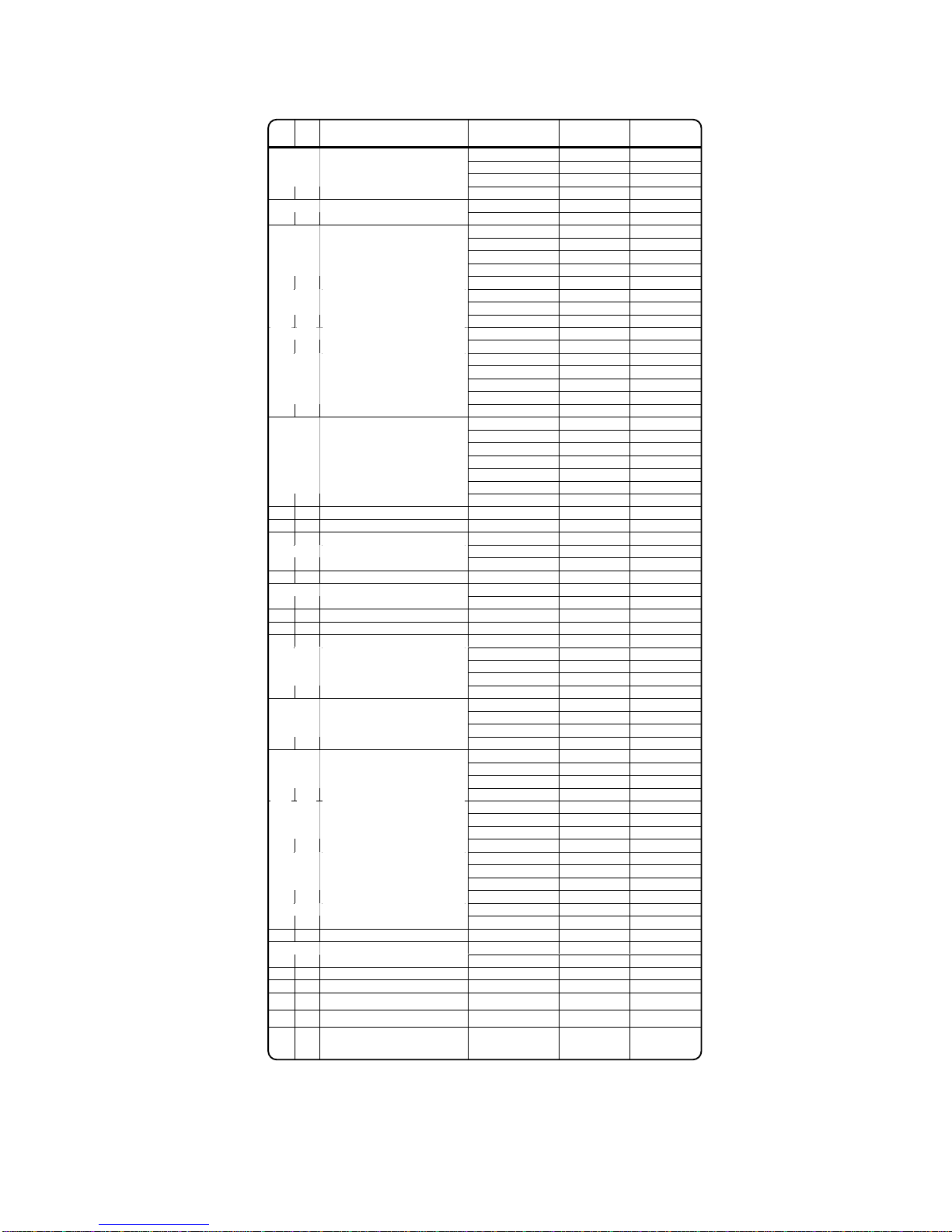
11I DELLMECO I AODD DIAPHRAGM PUMPS
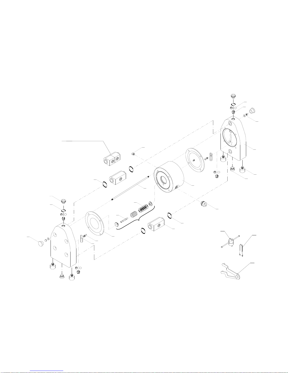
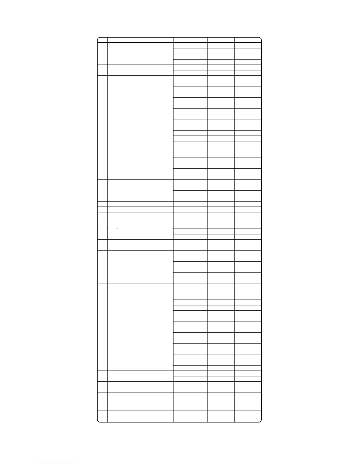
Spare parts list for DM 40/315 and DM 50/565 pumps
DM 40/315 DM 50/565
PE 2 40 01 20 2 50 01 20
PTFE 2 40 01 23 2 50 01 23
PE conductive 2 40 01 21 2 50 01 21
1. 2 Pump housing
PTFE conductive 2 40 01 24 2 50 01 24
PE 1 40 10 20 1 50 10 20
2. 1 Central housing PE conductive 1 40 10 21 1 50 10 21
PE 2 40 30 20 2 50 30 20
PTFE 2 40 30 23 2 50 30 23
PE conductive 2 40 30 21 2 50 30 21
PTFE conductive 2 40 30 24 2 50 30 24
3. 2 Suction/Discharge ports
AISI 316L 2 40 35 53 2 50 35 53
TFM/PTFE 1 40 50 05 1 50 50 05
EPDM 1 40 50 08 1 50 50 08
4. 2 Diaphragm
NBR 1 40 50 10 1 50 50 10
PE 2 40 56 20 2 50 56 20
5. 4 Cylinder valves PTFE 2 40 56 23 2 50 56 23
PTFE 1 40 60 23 1 50 60 23
EPDM 1 40 60 08 1 50 60 08
NBR 1 40 60 10 1 50 60 10
AISI 316 1 40 60 52 1 50 60 52
4 Valve balls
Polyurethane 1 40 60 07 1 50 60 07
EPDM/EPDM 2 40 70 08 2 50 70 08
FEP/FKM 2 40 70 04 2 50 70 04
NBR/NBR 2 40 70 10 2 50 70 10
PTFE/FKM 2 40 73 14 2 50 73 14
PTFE/EPDM 2 40 73 15 2 50 73 15
PTFE-c./FKM 2 40 73 16 2 50 73 16
7. 4 Sealing inlet/outlet - SET
PTFE-c./EPDM 2 40 73 17 2 50 73 17
9. 8 Housing bolt AISI 304 2 40 042 50 2 50 042 50
11. 4 Shock absorber NR/St37 1 40 69 06 1 40 69 06
12. 16 Nut with washer AISI 304 2 40 045 50 2 50 045 50
PET/NBR 1 40 020 31 1 40 020 31
13. 1 Air valve PET/FKM 1 40 020 32 1 40 020 32
14. 1 Shaft AISI 304 1 40 40 50 1 50 40 50
NBR 1 40 87 10 1 40 87 10
15. 6 O-ring FKM 1 40 87 09 1 40 87 09
16. 2 Central housing seal PE 1 40 85 22 1 50 85 22
17. 1 Muffler PE porous 1 40 99 35 1 50 99 35
18. 1 Air adapter PP 1 40 46 28 1 40 46 28
PE 2 40 54 20 2 50 54 20
PTFE 2 40 54 23 2 50 54 23
PE conductive 2 40 54 21 2 50 54 21
22. 4 Valve seat
PTFE conductive 2 40 54 24 2 50 54 24
PE 2 40 59 20 2 50 59 20
PTFE 2 40 59 23 2 50 59 23
PE conductive 2 40 59 21 2 50 59 21
24. 2 Plug lower
PTFE conductive 2 40 59 24 2 50 59 24
PE 2 40 055 20 2 50 055 20
PTFE 2 40 055 23 2 50 055 23
PE conductive 2 40 055 21 2 50 055 21
25. 2 Plug upper
PTFE conductive 2 40 055 24 2 50 055 24
PE 2 40 39 20 2 50 39 20
PTFE 2 40 39 23 2 50 39 23
PE conductive 2 40 39 21 2 50 39 21
26. 2 Valve stopper
PTFE conductive 2 40 39 24 2 50 39 24
PE 2 40 38 20 2 50 38 20
PTFE 2 40 38 23 2 50 38 23
PE conductive 2 40 38 21 2 50 38 21
27. 2 Bolt
PTFE conductive 2 40 38 24 2 50 38 24
FEP/FKM 2 40 78 04 2 50 78 04
28. 2 Plug upper sealing EPDM 2 40 78 08 2 50 78 08
30. 2 O-ring for central housing seal NBR 1 40 85 10 1 50 85 10
PE 1 40 11 20 1 50 11 20
35. 1 Central housing complete PE conductive 1 40 11 21 1 50 11 21
40. 1 DELLMECO nameplate Diverse 1 40 094 00 1 50 094 00
70. 16 Pump housing plug PE 2 40 058 20 2 50 058 20
82. 2 Shaft allen pin screw AISI 304 1 40 540 50 1 50 540 50
97. 1 Valve seat key AISI 304 1 40 254 50 1 50 254 50
99. 1 Upper/lower plugs and air valve
key (SK3, SK4) diverse 1 08 58 00 1 08 58 00

12 I DELLMECO I AODD DIAPHRAGM PUMPS
1
2
3
4
7
7
9
11
12
13
15
14
17
22
24
25
26
27
28
16
30
3
5
18
70
82
83
97
98
99
5.4. DM 80/850

13I DELLMECO I AODD DIAPHRAGM PUMPS
Spare parts list for DM 80/850 pump
DM 80/850
PE 2 80 01 20
1. 2 Pump housing PE conductive 2 80 01 21
PE 1 80 10 20
2. 1 Central housing PE conductive 1 80 10 21
PE 2 80 25 20
1 Suction port PE conductive 2 80 25 21
PE 2 80 025 20
3.
1 Discharge port PE conductive 2 80 025 21
TFM/PTFE 1 80 50 05
EPDM 1 80 50 08
4. 2 Diaphragm
NBR 1 80 50 10
PTFE 1 80 60 23
EPDM 1 80 60 08
5. 4 Valve balls
NBR 1 80 60 10
EPDM/EPDM 2 80 70 08
FEP-FKM/FKM 2 80 73 14
FEP-FKM/EPDM 2 80 73 15
7. 4 Sealing inlet/outlet - SET
NBR/NBR 2 80 73 10
9. 8 Housing bolt AISI 304 2 80 042 50
11. 4 Shock absorber NR/St37 1 80 69 06
12. 16
Nut with washer, cpl. AISI 304 2 80 045 50
PET/NBR 1 80 020 31
13. 1 Air valve PET/FKM 1 80 020 32
14. 1 Shaft AISI 304 1 80 40 50
NBR 1 40 87 10
15. 6 O-ring FKM 1 40 87 09
16. 2 Central housing seal PE 1 80 85 22
17. 1 Muffler Diverse 1 80 99 00
18. 1 Air adapter PP 1 80 46 28
PE 2 80 54 20
22. 4 Valve seat PE-conductive 2 80 54 21
PE 2 80 59 20
24. 2 Plug lower PE-conductive 2 80 59 21
PE 2 80 55 20
25. 2 Plug upper PE conductive 2 80 55 21
PE 2 80 39 20
26. 2 Valve stopper PE conductive 2 80 39 21
PE 2 80 38 20
27. 4 Bolt PE conductive 2 80 38 21
FEP/FKM 2 80 78 04
EPDM 2 80 78 08
28. 2 Plug upper sealing
NBR 2 80 78 10
30. 2 O-ring for central housing seal
NBR 1 80 85 10
PE 1 80 11 20
35. 1 Central housing complete PE conductive 1 80 11 21
40. 1 DELLMECO nameplate Diverse 1 80 094 00
70. 16
Pump housing plug PE 2 80 058 20
82. 2 Shaft allen pin screw AISI 304 1 80 540 50
83. 1 Muffler adapter PE 1 80 299 20
97. 1 Valve seat key AISI 304 1 80 254 50
98. 1 Upper/lower plugs key (SK5) diverse 1 80 158 00
99. 1 Air valve key (SK4) diverse 1 08 58 00

14 I DELLMECO I AODD DIAPHRAGM PUMPS
6. Assembly
7. Installation
7.1.Installing the pump
1) Decide where the pump is to be installed and secure a site.
Note:
-The suction lift should be kept as short as possible.
-Sufficient space around the pump for maintenance must be provided.
When fixing the pump in place, use the cushions on the pump base. The tied-down bolts should be tightened
a little at a time to secure the pump.
SELF PRIMING APPLICATION
Suction lift capability may vary depending on the construction materials and
application parameters. The range is from 5 meters dry to 9 meters in a primed
condition (values calculated for pumping water at 20 degrees Celsius).
SUBMERGED OPERATION
All pumps may operate in full submersion. Construction materials must be
compatible with surrounding liquid and the air exhaust must be placed
above the liquid level.
POSITIVE SUCTION HEAD
Common as a method of drawing off the bottoms of holding tanks and
clarifiers. Optimum inlet pressure should be kept at 0.2-0.3 bar.
!
!!
!
CAUTION
!
!!
!When installing accessories prevent any foreign matter from getting into the product.
Otherwise malfunction of the air-valve may follow.

15I DELLMECO I AODD DIAPHRAGM PUMPS
Size
DM 08/10
DM 10/25 DM 15/55 DM 25/125 DM 40/315 DM 50/565 DM 80/850
Max number of strokes/min. at
nominal performance
500 430 240 160 140 100 100
Size DM 08/10
DM 10/25 DM 15/55 DM 25/125
DM 40/315
DM 50/565
DM 80/850
Torque values for housing
bolts (Nm):
PE pumps
PTFE pumps
3
2
6
5
8
7
13
11
17
15
22
19
24
-
!
!!
!
CAUTION
!
!!
!
WARNING
!
!!
!
CAUTION
!
!!
!Vibration generated by pump operation should be absorbed. Take it into consideration when mounting it.
!
!!
!When using the pump in submerged position, follow the steps below:
- Verify the corrosion resistance of each component of the pump. DO NOT expose the pump to any fluid
for which it does not have proper corrosion resistance.
- Exhaust should direct outside, not into the fluid in which the pump is submerged.
!
!!
!The running pump may generate noise. Its level will depend upon conditions of use (kind of fluid being
pumped, supply air pressure and discharge pressure).
!
!!
!The end of the hose must be equipped with a pit, a protection box, etc. at the end of the hose in case the
diaphragm gets damaged and a leakage of the fluid follows.
!
!!
!Pump exhaust should be directed to a safe place, away from people, animals and food.
!
!!
!Before putting the pump into operation as well as after some hours of pumping, the housing bolts have to
be fixed according to the torque data of the following schedule, as the elements of construction “settle”.
Both lower and upper plugs [24, 25] have to be fixed, too. Fixing all these parts is necessary as well
after longer periods of stoppage, at extreme temperature variations, after transport and dismantling the
pump.

16 I DELLMECO I AODD DIAPHRAGM PUMPS
7.2. Connecting the ground wire
a) When installing the conductive pump, be sure to connect the ground wire at the specified position.
b) Ground wires should be connected to peripheral equipment and piping as well.
c) Use 2.0 mm
2
minimum ground wire.
8.
Connection
8.1. Connecting fluid piping
1) Connect a flow valve and a drain valve to the fluid discharge port of the pump.
2) Connect a valve for maintenance to the fluid suction intake port of the pump.
3) Connect a hose to the valve on the suction-port side and the valve of the discharge-port side of the pump.
4) Connect a hose on the suction-side intake and the discharge-port side to the respective vessels.
!
!!
!
WARNING
!
!!
!Ground wires must be connected to the piping and any other peripheral equipment. When operating the
pump make sure it is properly grounded. Otherwise friction between the parts and abrasion caused by
some fluids flowing inside the casing may generate static electricity. In addition it may cause fire or
electric shock, depending on the type of fluid being pumped and the installation environment (such as
gases in the air or the surrounding mixtures).
flexible connection
flexible
connection
vacuum
gauge
shut-off
valve
shut-off
valve
pressure
gauge
SUCTION
DISCHA GE
air shut-off
valve
combined air
filter and
regulator
needle
valve
AI SUPPLY

17I DELLMECO I AODD DIAPHRAGM PUMPS
8.2. Connecting air piping
1) Connect an air valve, air filter, regulator to a hose connected to the compressor. Install items near the pump.
2) Connect the hose from the peripheral equipment to the air valve of the pump's supply port.
Note:
The diameter of the piping should be the same as the diameter of the pump supply port in order to supply sufficient air.
Peripheral equipment with sufficient airflow should be chosen to meet the requirement of the pump air consumption.
It must be installed nearest the pump unit, even using dry air. Usage and stability of air pressure must be considered.
!
!!
!
WARNING
!
!!
!
CAUTION
!
!!
!A hose must be flexible to absorb pump vibration. The hose must be grounded.
!
!!
!
There must be NO external force on any connection part of the pump. Be especially careful not to have
the pump support part of the weight of the hose and the piping.
!
!!
!Use a sturdy hose that will not collapse under the strong suction of the pump. The hose must be of more
than sufficient pressure rating.
!
!!
!Use a hose of a diameter the same as or larger than the pump's ports. If the diameter of a hose is
smaller, it will affect the pump's performance or cause its malfunction.
!
!!
!Keep a vessel below the relief valve to catch any drain off.
!
!!
!The product has been inspected using clean water at 8 bar discharge pressure.
!
!!
!Before starting work, make sure that the air compressor is shut off.

18 I DELLMECO I AODD DIAPHRAGM PUMPS
9. Operation
9.1. Method of operation
1) Start the air compressor.
2) Open the air valve. Using a regulator adjust the supply air pressure to within the permissible range.
3) Open the flow valve on the discharge side.
4) First, check that fluid is flowing inside the piping and is being pumped to the discharge side, and then fully open the
air valve.
9.2. Flow adjustment
Adjust the flow valve on the discharge side, or adjust the supply air pressure.
!
!!
!
CAUTION
!
!!
!
CAUTION
!
!!
!
CAUTION
!
!!
!Before starting the pump, check that all piping is properly connected.
!
!!
!Before starting the pump, check that all the bolts are securely tightened.
!
!!
!Check that the regulator and the drain valve on the discharge side are closed and that the valve on
the suction side is opened.
Ø Do NOT open the air valve suddenly.
!
!!
!The supply air pressure may initially rise during closing the flow valve. Make sure that the pressure is kept
within the normal operating range.
!
!!
!The permissible suction flow speed can vary depending upon the viscosity and specific gravity of the fluid,
the suction stroke and other factors. However in case of a rapid growth of the pump speed (flow speed of
fluid), cavitations will occur This will reduce pump performance and may cause a malfunction. In order to
prevent cavitations, adjust the supply air pressure and the flow.
!
!!
!If fluid is not discharged after you start the pump, or if you hear an abnormal noise or notice any
irregularity, shut down the pump immediately.

19I DELLMECO I AODD DIAPHRAGM PUMPS
9.3. Shutdown
Close the air valve of the pump and shut off the supply air.
10. Method of cleaning
1) Remove the hose from the suction side of the pump.
2) Close the flow valve on the discharge side and open the drain valve. Then start air pressure
for a while to discharge possibly much fluid remaining inside the pump.
3) Remove the hose from the discharge side, and attach different hoses to the suction side
and the discharge side for cleaning.
4) Be ready with a vessel with cleaning solution, the kind appropriate for the type of fluid
pumped. Next connect the suction-side and the discharge-side hoses of the pump.
5) Start the pump air pressure slowly, and let the cleaning solution circulate for sufficient
cleaning.
6) Flush with clean water.
7) Remove the hose from the suction side of the pump, run the pump for a while to purge the
pump of remaining fluid as much as possible.
!
!!
!
WARNING
!
!!
!
CAUTION
!
!!
!
CAUTION
!
!!
!The pump can be shut down with the flow valve closed while air is being supplied. However DO NOT leave
the pump in this condition for many hours without supervision - there is a risk of a leak from the pump or
piping, and fluid may continue flowing out of the position of leakage.
!
!!
!When the pump is shut down while pumping slurry, particulate matter contained in the slurry will be
deposited and get stuck inside the out chamber. Therefore after finishing work the pump must be purged of
the remaining fluid. Otherwise when starting the pump again, the diaphragm may get damaged and the
centre rod may bend.
!
!!
!Keep a vessel below the relief valve for any drain off.
!
!!
!Be careful! - Fluid under pressure will gush out the moment you open the valve.
!
!!
!
If the pump is unused for a prolonged period, purge and clean it.
!
!!
!Make sure that compressed air is not supplied to the pump BEFORE you start cleaning the pump.
!
!!
!Make sure that the pump is not pressurized BEFORE you start cleaning the pump.

20 I DELLMECO I AODD DIAPHRAGM PUMPS
11. Dailycheck
Before starting pump operation, conduct the following check procedures every day. In case there
appears any irregularity, do NOT start running the pump until the cause of the irregularity has been
determined and corrective measures have been taken.
a)Make sure that there is no leakage of fluid from any connection part or the pump.
b)Make sure that there are no cracks in the pump casing or piping.
c)Check the tightness of every bolt of the pump.
d)Make sure that the connection parts of the piping and peripheral equipment are not loose.
e)Make sure that any parts of the pump that are to be replaced at regular intervals have been
changed.
12. Possible problems
12.1. Pump does not run
Cause Action to take
The exhaust port (muffler) of pump is clogged with
sludge.
Check and clean the exhaust port and muffler.
Air is not supplied.
Start the compressor, and open the air valve and air
regulator.
The supply air pressure is low.
Check the compressor and the configuration of air
piping.
Air leaks from connection parts.
Check the connection parts and tightness of bolts.
The flow valve on the discharge side is not open.
Open the flow valve on the discharge side.
The fluid piping is clogged with sludge.
Check and clean the fluid piping.
The pump is clogged with sludge.
Disassemble the casing, check and clean.
!
!!
!
CAUTION
!
!!
!Be extremely careful when removing piping - the fluid will gush out.
!
!!
!After cleaning with clean water, turn the pump upside-down to let the water flow out.
This manual suits for next models
6
Table of contents
Other Dellmeco Water Pump manuals
Popular Water Pump manuals by other brands

GORMAN-RUPP
GORMAN-RUPP AMT 5760-95 Specifications information and repair parts manual

Orbit
Orbit PP Series Installation and operating instructions

Aurelaqua
Aurelaqua PRP-125 user manual

Graco
Graco Python A25115 Instructions - parts

GORMAN-RUPP
GORMAN-RUPP 10 SERIES Installation, operation, and maintenance manual with parts list

LEYBOLD
LEYBOLD Ruvac WH 700 Installation and operating instructions