DeLonghi AWR-MTD2-XE Setup guide

INSTALLATION - OPERATING - SERVICE MANUAL
Reverse-cycle air/water heat pumps with
domestic hot water production, axial-flow
fans and water pump assembly.
EN
AWR-MTD2-XE
0011÷0091

2AWR-MTD2-XE EN 11/2010
U I A
User
Installer
Assistance
Important
Prohibition
Danger voltage
Danger high temperatures
INDEX U I A
The manufacturer reserves the right to modify the data in this manual without warning.
Eurovent certification program.
The following symbols are used in this publication and inside the unit:
U
I
A
General warnings 3
Waiver of liability 3
Fundamental safety rules 3
Receiving and handling the product 4
Unit identification 5
Description of standard unit 6
Dimensioned drawings 7
Installation 7
Water connections 8
Electrical connections 11
Installer connections 12
Mains power supply connections 15
Installer connections 14
General technical data 32
Operating limits 33
Pump curve 34
Checking and starting up the unit 36
Description of room controller buttons and 38
display
Operation and functions of the room controller 39
Control and operating characteristics 48
System configuration 53
Maintenance and service 59
Peak limiter alarm signals 61
Shutting down for long periods 62
Scheduled maintenance 62
Unscheduled maintenance 63
Disposal 63
List of parameters 64
Installer operations CHECKLIST 66
U I A A
U
U
I A
I A
I
IU
I A
A
A
I
I
I
I
A
A
I A
I A
I A
I A
I A
I A
A
A
A
AIU
A
A
A
A
A
A
AIU
AIU

3EN 11/2010 AWR-MTD2-XE
GENERAL WARNINGS U I A
FUNDAMENTAL SAFETY RULES U I A
These appliances have been designed to chill and/or
heat water and must be used in applications compatible
with their performance characteristics; these appliances
are designed for residential or similar applications.
Incorrect installation, regulation and maintenance or
improper use absolve the manufacturer from all liability,
whether contractual or otherwise, for damage to people,
animals or things.
Only those applications specifically indicated in this list
are permitted
Read this manual carefully. All work must be carried
out by qualified personnel in conformity with legislation in
force in the country concerned.
The warranty is void if the above instructions are not
respected and if the unit is started up for the first time
without the presence of personnel authorised by the
Company (where specified in the supply contract) who
should draw up a “start-up” report.
The documents supplied with the unit must be con-
signed to the owner who should keep them carefully for
future consultation in the event of maintenance or service.
All repair or maintenance work must be carried out by
the Company’s Technical Service or qualified personnel
following the instructions in this manual.
The air-conditioner must under no circumstances be
modified or tampered with as this may create situations
of risk. Failure to observe this condition absolves the
manufacturer of all liability for resulting damage.
When operating equipment involving the use of electricity and water, a number of fundamental safety rules must be observed,
namely:
The unit must not be used by children or by unfit per-
sons without suitable supervision.
Do not touch the unit with bare feet or with wet or
damp parts of the body.
Never perform any cleaning operations before having
disconnected the unit from the mains power supply.
Do not modify safety or control devices without authori-
sation and instructions from the manufacturer.
Do not pull, detach or twist the electrical cables coming
from the unit, even when disconnected from the mains
electricity supply.
Do not open doors or panels providing access to the
internal parts of the unit without first ensuring that the
switch QF1 is in the OFF position (see the wiring dia-
gram).
Do not introduce pointed objects through the air
intake and outlet grills.
Do not dispose of, abandon or leave within reach of
children packaging materials (cardboard, staples, plastic
bags, etc.) as they may represent a hazard.
Respect safety distances between the unit and other
equipment or structures. Guarantee adequate space for
access to the unit for maintenance and/or service opera-
tions.
Power supply: the cross section of the electrical cables
must be adequate for the power of the unit and the pow-
er supply voltage must correspond with the value indicat-
ed on the respective units. All units must be earthed in
conformity with legislation in force in the country con-
cerned.
Terminals 6, 7, 9, 10, 11, 12, 13, 21, 22, 23, 24, may be
live even after the unit is disconnected. Make sure power
is not connected before proceeding.
Water connections should be carried out as indicated in
the instructions to guarantee correct operation of the
unit. Add glycol to the water circuit if the unit is not used
during the winter or the circuit is not emptied.
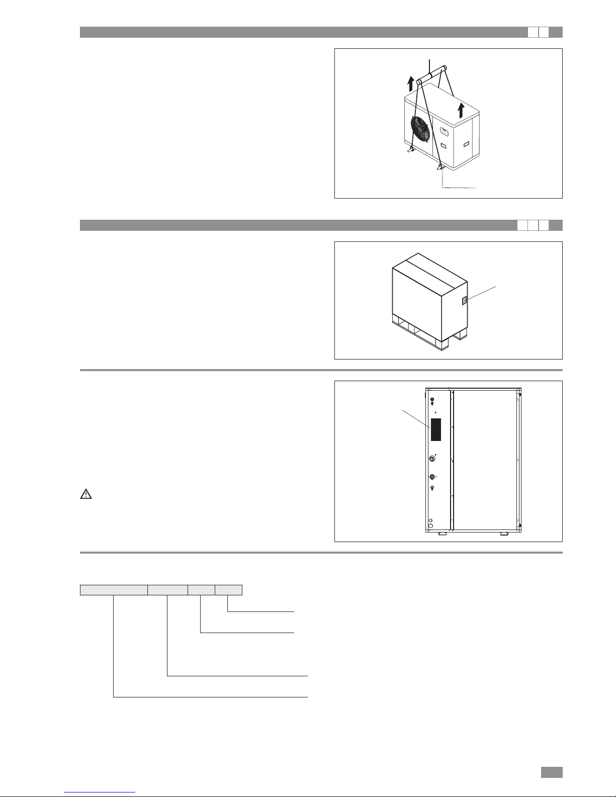
Handle the unit with the utmost care (see weight distrib-
ution table) to avoid damage.
WAIVER OF LIABILITY
This publication is the sole property of Manufacturer. Any
reproduction or disclosure of such is strictly prohibited with-
out the written authorisation of Manufacturer.
This document has been prepared with maximum care and
attention paid to the content shown. Nonetheless, Manufac-
turer waives all liability deriving from the use of such docu-
ment.
Read this document carefully. All work must be performed,
components selected and materials used in complete accor-
dance with the legislation in force in material in the country
concerned, and considering the operating conditions and
intended uses of the system, by qualified personnel.
U I A

4AWR-MTD2-XE EN 11/2010
Dimensions 0011 0025 0031 0041 0051 0061 0091
Dimension L mm 970 970 970 970 970 1600 1600
Dimension P mm 525 525 525 525 525 610 610
Dimension H mm 1450 1450 1450 1600 1600 1360 1850
Gross weight Kg 165 170 175 190 200 275 360
VISUAL INSPECTION
When the items are consigned by the carrier:
- make sure that the goods delivered correspond to the
description on the delivery note, comparing this against
the data on the packaging label.
- make sure the packaging and the unit are intact.
If damage or missing components are noted, indicate this on
the delivery note. A formal complaint should be sent via fax
or registered post to the After Sales Department within eight
days from the date of receipt of the items.
HANDLING PACKAGED UNITS
The unit should always be handled by qualified personnel
using equipment adequate for the weight of the unit, in com-
pliance with the safety standards in force (and subsequent
amendments).
•Lifting by forklift (1)
Insert the forks under the long side of base, opening the
forks as fare as possible.
•Lifting by crane (2)
Use slings with hooks suitable for the weight being lifted.
Secure the hook to the lifting bracket fixed to the unit, use
always four equal length slings, as shown in the figure, to
ensure the weight is balanced.
REMOVING THE PACKAGING
The packaging must be removed by the operator using suit-
able protective equipment (gloves, glasses, etc.).
Take special care not to damage the unit. Observe the local
standards in force as regards disposal of the packaging,
using specialist collection or recycling centres.
Do not dispose of packaging materials in the environ-
ment or leave them within reach of children as they may
represent a hazard.
Envelope A, located in the compressor compartment, con-
tains:
• instruction manual;
• warranty certificate;
• CE declaration;
• list of the main components and sub-assemblies fitted on
the product
• remote room control unit A5 (must be installed)
• DHW storage water temperature probe BT8
• outside air temperature probe BT11 (must be installed)
• probe BT9 only to be installed when supplementary
source is available
Make sure the components listed above are not lost or mis-
placed.
The instruction manual is an integral part of the unit
and should therefore be read and kept carefully.
STORING THE UNITS
The units must be stored sheltered from direct sunlight, rain,
wind or sand.
Avoid exposing the units to direct sunlight, as the pressure
inside the refrigerant circuit may reach dangerous values
and cause the activation of the safety valves, where fitted.
The units cannot be stacked.
RECEIVING AND HANDLING THE PRODUCT I A
H
PL
Bar code
(compressor side)
A
1
2

5EN 11/2010 AWR-MTD2-XE
RECEIVING AND HANDLING THE PRODUCT I A
HANDLING UNPACKAGED UNITS
When the packaging has been removed:
• Remove the wooden base.
• Fit the vibration damping feet (accessories).
• Handle the unit using equipment that is suitable for its
weight (forklift or crane), in compliance with the safety
standards in force (and subsequent amendments).
• Do not drag the unit as the feet may be damaged or break.
Hole Ø22
UNIT IDENTIFICATION U I A
The heat pump can be identified from:
PACKAGING LABEL
Describes the product identification data
RATING PLATE
Describes the unit technical and performance specifications.
Shows the serial number used to uniquely identify the unit.
The serial number is also used to identify the unit’s spare
parts.
If service is required, the following information must be pro-
vided to the service centre:
Model, serial number, year of production.
Installation and maintenance operations are much more
difficult if the identification plates or anything else need-
ed to clearly identify the product are tampered with,
removed or missing.
NOMENCLATURE
Packaging label
Rating plate
with serial number
AWR MTD2 XE 0011 m s
Power supply voltage:
m = 230V/50Hz/1ph
t = 400V/3N/50Hz
size
s = peak limiter
Model

6AWR-MTD2-XE EN 11/2010
DESCRIPTION OF STANDARD UNIT I A
These air cooled reverse-cycle chillers with axial-flow fans
operate with R410A refrigerant fluid and are suitable for out-
door installation.
The units are CE marked, as established by the EU directives,
including the latest amendments, and the corresponding
approximated national legislation.
They are factory tested and on site installation is limited to
water and electrical connections.
VERSIONS AVAILABLE
AWR-MTD2-XE
Reverse-cycle air/water heat pump with domestic hot water production. Built-in water pump assem-
bly without electric heaters.
11
10
15
13
4
20
14
6
8
5
12
3
19
18
17
16
21
9
1
2
7
1 Electrical panel
2 NadiSystem controller
3 System plate heat exchanger
4 Low pressure switch
5 High pressure switch
6 Liquid sight glass (0041 - 0061)
7 Scroll compressor
8 Filter
9 Thermostatic valve
10 Axial-flow fan
11 Airside finned heat exchanger
12 Pump
13 Liquid recipient
14 Expansion vessel
15 Reversing valve
17 Safety valve
18 Air vent valve
19 Pressure gauge
20 Base electric heater
21 Pressure transducer

7EN 11/2010 AWR-MTD2-XE
U I A
DIMENSIONED DRAWINGS I
600
W1 W2
W4 W3
900
D
B
C
=E
A
=
400
Dimensions 0011 0025 0031 0041 0051 0061 0091
A mm 900 900 900 900 900 1550 1550
B mm 1240 1240 1240 1390 1390 1200 1700
C mm 420 420 420 420 420 450 450
D mm 370 370 370 370 370 497 497
E mm 580 580 580 580 580 1477 1477
Weight distribution 0011 0025 0031 0041 0051 0061 0091
W1 lato rear dx kg 60 62 64 67 71 88 117
W2 lato rear sx kg 17 18 20 23 24 39 54
W3 front sx kg 17 18 18 22 22 36 51
W4 front dx kg 51 52 53 58 63 87 113
tot kg 145 150 155 170 180 250 335
INSTALLATION I
CHOICE OF INSTALLATION SITE
Before installing the unit, agree with the customer the site
where it will be installed, taking the following points into con-
sideration:
• check that the support surface is adequate to support the
weight of the unit;
• respect safety distances between the unit and other equip-
ment or structures so that the fan air intake and outlet are
not blocked in any way.
• Follow the instructions shown in the chapter on DIMEN-
SIONED DRAWINGS to allow room for maintenance oper-
ations.
If installing multiple units the clearances must be doubled.
POSITIONING
• Install the vibration damping feet (accessories).
• Check the unit supports and weights before positioning
• Make sure that the unit is level, adjust the height of the
support feet if necessary
• Use the flexible joints supplied for the water connections
• Make sure there is easy access to the water circuit and
electrical parts
• For installation, if the site is exposed to strong winds, fix
the unit adequately using tie rods if necessary.
• In heating mode the unit produces a significant quantity of
condensate, which must be suitably drained.
Condensate drainage must not cause problems to objects
or people.
• If the outside air temperature is less than 0°C, the conden-
sate may freeze; in these case fit a frost protection heater
on the drain line.
• Consider the maximum height that may be reached by
snow to avoid blocking the air intake or outlet (outdoor
installation)
• Unit for outdoor installation
For correct operation of the unit, avoid the following:
• obstacles to air flow, such as leaves that may block the
heat exchange coil
• strong winds that stop or reinforce air flow
• sources of heat too close to the unit
• air recirculation between intake and outlet
• poor air change
• stratification of air

8AWR-MTD2-XE EN 11/2010
WATER CONNECTIONS I A
Warnings
- The choice and installation of components is the responsi-
bility of the installer who should follow good working prac-
tice and current legislation.
Before connecting the pipes make sure that these:
- do not contain stones, sand, rust, scale or any foreign
objects that may damage the system.
- wash the system with clean water
Water connection dimensions
Components
The following components should be installed for correct
installation of the unit:
1. Two pressure gauges with a suitable scale (inlet and out-
let);
2. Two vibration damper joints (inlet and outlet).
3. Shut-off valves at the inlet and outlet.
4. A flow switch at the unit outlet on the system circuit
(compulsory). The flow switch must be calibrated by the
installer to a value equal to 70% of rated flow.
5. Two thermometers (inlet and outlet);
6. An inlet filter (compulsory) as close as possible to the
unit and positioned to allow easy access for scheduled
maintenance (both on the system circuit and domestic
hot water circuit).
7. All the pipes must be insulated with suitable material to
prevent the formation of condensate and heat loss.
The insulating material must be a vapour barrier.
Make sure that the control and shut off devices protrude
from the insulation.
8. At the lowest points in the system, install drain valves for
easy emptying.
9. At the highest points in the system, install automatic or
manual air vent valves.
10. The unit is fitted as standard with an expansion vessel;
make sure this is correctly sized for the water content of
the system and the expected operating temperature, oth-
erwise install an additional expansion vessel.
D
100
B
C
528.5
563.5
A
A = C
D
EB
85
35
328
85
0011-0051
SAFETY VALVE
DISCHARGE
UNIT VENT
WATER INLET
WATER OUTLET
SYSTEM FILL G1/2
0061-0091
SYSTEM FILL G1/2
WATER OUTLET
WATER INLET
UNIT VENT
SAFETY VALVE DISCHARGE
OPENING FOR CONDENSATE DRAIN CONNECTION
Dimensions 0011 0025 0031 0041 0051 0061 0091
A mm 61,5 61,5 61,5 61,5 61,5 90,5 90,5
B mm 617 617 617 717,5 717,5 575 770
C mm 57 57 57 57 57 90,5 90,5
D mm 454,5 454,5 454,5 549,5 549,5 120 120
E mm - - - - - 560 551
Water in fittings Ø 1" 1" 1" 1" 1/4 1" 1/4 1" 1/4 1" 1/4
Water out fittings Ø 1" 1" 1" 1" 1/4 1" 1/4 1" 1/4 1" 1/4

9EN 11/2010 AWR-MTD2-XE
11. The connection piping should be supported in such a way
as to avoid it weighing on the unit.
Failure to install the flow switches will mean the heat
exchangers are not protected in the event of no flow of
liquid. The Manufacturer cannot be held liable for any
damage to the unit and/or the system following the fail-
ure to install these devices or the filter.
The correct operation of the components that help
ensure the safety of the appliance and the system
should be checked regularly:
• make sure the filters are clean
• check operation of the flow switches installed.
• Make sure that the frost protection heaters on the heat
exchanger are powered when the unit is OFF
Water flow to the heat pump must conform to the values
shown in the section on “General Technical Data”.
The flow of water must be maintained constant during oper-
ation.
The water content of the unit must be such as to avoid dis-
turbing operation of the refrigerant circuits.
Risk of freezing
The unit must be prevented from freezing at outside air tem-
peratures around 0°C.
The following are recommended:
• use suitable percentages of antifreeze (see “Ethylene gly-
col solutions”)
• protect the piping with heating sheaths,
• empty the system, making sure no water remains at the
lowest points in the circuit or there are closed valves
where water may stagnate.
It is recommended to use non-toxic food grade antifreeze,
compliant with the standards in force in the countries where
the unit is used, if domestic hot water production is also fea-
tured.
The antifreeze used must be corrosion inhibited and com-
patible with the water circuit components.
Ethylene glycol solutions
Water and ethylene glycol solutions used as a heat carrier in
the place of water reduce the performance of the unit.
Multiply the performance figures by the values given in the
following table.
The heat pumps must be fitted with a filling/top-up sys-
tem connected to the return line and a drain valve in the
lowest part of the system.
Systems containing antifreeze or covered by specific
legislation must be fitted with low-loss headers.
cPf
cQ
cdp
0
1
1
1
12%
0,985
1,02
1,07
20%
0,98
1,04
1,11
28%
0,974
1,075
1,18
35%
0,97
1,11
1,22
40%
0,965
1,14
1,24
0 -5 -10 -15 -20 -25
Freezing point (°C)
Percentage of ethylene glycol by weight
cPf: cooling capacity correction factor
cQ: flow rate correction factor
cdp: pressure drop correction factor
Fouling factors
The performance data given refer to conditions with clean
evaporator plates (fouling factor = 1).
For different fouling factors, multiply the figures in the perfor-
mance tables by the coefficient given in the following table.
f1: capacity correction factor
fk1: compressor power input correction factor
fx1: total power input correction factor
4,4 x 10⁻⁵
0,86 x 10⁻⁴
1,72 x10⁻⁴
-
0,96
0,93
-
0,99
0,98
-
0,99
0,98
Fouling factors
(m2°C/W) f1
Evaporator
fk1 fx1
Water quality
The water used in the system and domestic hot water cir-
cuits must comply with the following characteristics:
PH 6-8
Electrical conductivity less than 200 mV/cm (25°C)
Chlorine ions less than 50 ppm
Sulphuric acid ions less than 50 ppm
Total iron less than 0.3 ppm
Alkalinity M less than 50 ppm
Total hardness less than 50 ppm
Sulphur ions none
Ammonia ions none
Silicon ions less than 30 ppm
WATER CONNECTIONS I A

10 AWR-MTD2-XE EN 11/2010
WATER CONNECTIONS I A
Water content in the system
Size 0011 0025 0031 0041 0051 0061 0091
Minimum water content l 24 31,5 40 46 65 74 110
Expansion vessel size
Size 0011 0025 0031 0041 0051 0061 0091
Expansion vessel l 2222244
Safety valve calibration
Size 0011 0025 0031 0041 0051 0061 0091
Safety valve bars 6666666
Factory connections Installer connections
1
2
12
12
13
14
14 UTILITY
RETURN
UTILITY
OUTLET
98716
3
11
T
6
15
16
T
6
F
5
4
2
10
1
1
9
Utility water circuit connection diagram
1 Pressure gauge
2 Vibration damper joint
3 Shut off valve
4 Calibrating valve
5 Flow switch
6 Thermometer
7 Pump
8 Safety valve
9 Expansion vessel
10 Wire mesh filter
11 Unit fill/drain valve
12 Temperature sensor
13 Differential pressure switch
14 Drain / chemical washing valve
15 System vent
Condensate drain
In heating mode the unit produces a significant quantity of
condensate, which must be suitably drained.
Proceed as follows:
• Connect the unit condensate drain
• Make sure the drain hose has a incline of at least 2 cm/m,
without obstructions or choking.
• Connect the condensate drain hose to a rainwater drain.
Do not connect to the sewage system as odours may be
sucked up if the water in the drain trap evaporates.
• After connecting, check correct drainage of the conden-
sate by pouring water into the pan.
• If necessary, suitably insulate the condensate drain hose.
• Condensate drainage must not cause problems to objects
or people.
• If the outside air temperature is less than 0°C, the conden-
sate may freeze.
The unit comes with frost protection for the condensate col-
lection basin inside the unit.
Use hot wires on the condensate drain hose downstream of
the unit to protect against frost.
FILLING THE SYSTEM
- Before starting to fill, place the unit mains
switch QF1 in the OFF position.
- Before filling, check that the system drain
valve is closed.
- Open all system and terminal air vents.
- Open system shut off valves.
- Start filling by slowly opening the system water fill valve out-
side the unit.
- When water begins to leak out of the terminal air vent valves,
close them and continue filling until the pressure gauge indi-
cates a pressure of 1.5 bar.
The system must be filled to a pressure of between 1
and 2 bars.
It is recommended that this operation be repeated after
the unit has been operating for a number of hours. The
pressure in the system should be checked regularly and
if it drops below 1 bar, the water content should be
topped-up.
Check the tightness of the joints.
ON
OFF

11EN 11/2010 AWR-MTD2-XE
ELECTRICAL CONNECTIONS I A
The heat pumps must be installed downstream of a main
switch (QF1, see wiring diagram), as required by the stan-
dards in force in the country where the unit is installed. Con-
nection to the mains power supply and the connection of the
flow switch to the corresponding terminals must be per-
formed by authorised personnel in compliance with the stan-
dards in force.
For all electrical work, refer to the electrical wiring diagrams
in this manual.
It is also recommended to check that:
- The characteristics of the mains electricity supply are ade-
quate for the power ratings indicated in the electrical spec-
ifications below, also bearing in mind the possible use of
other equipment at the same time.
Power to the unit must be turned on only after installa-
tion work (plumbing and electrical) has been completed.
All electrical connections must be carried out by quali-
fied personnel in accordance with legislation in force in
the country concerned
Respect instructions for connecting phase, neutral and
earth conductors..
The power line should be fitted upstream with a suitable
device to protect against short-circuits and leakage to
earth, isolating the installation from other equipment.
Voltage must be within a tolerance of ±10% of the rated
power supply voltage for the unit (for three phase units,
the unbalance between the phases must not exceed 3%).
If these parameters are not respected, contact the elec-
tricity supply company.
For electrical connections, use double insulation cable
in conformity with legislation in force in the country con-
cerned..
A thermal overload switch and a lockable mains dis-
connect switch, in compliance with the CEI-EN stan-
dards (contact opening of at least 3mm), with ade-
quate switching and residual current protection
capacity based on the electrical data table shown
below, must be installed as near as possible to the
appliance.
An efficient earth connection is obligatory.
The manufacturer cannot be held liable for any damage
caused by the failure to correctly earth the unit.
In the case of three phase units, ensure the phases
are connected correctly.
Do not use water pipes to earth the unit.
Electrical data at maximum conditions allowed (full load)
F.L.I. Maximum power input
F.L.A. Maximum current input
L.R.A. Start-up current
Maximum values for sizing the protection switches and power supply cables.
Size
Power
supply
Maximum values Fuses
(5x20T 250V)
Heater
Power consumption without heater
Total power consumption
L.R.A.
[A]
FU1 FU5 FU6
(V-Ph-Hz) P MAX [kW] I MAX [A] P MAX TOT [kW] I MAX TOT [A] F.L.I. [kW] F.L.A. [A] [A] [A] [A]
0011ms 230-1N-50 - - - - 2,82 13,5 27 1,6 4 1,25
0025ms 230-1N-50 - - - - 3,56 16,7 30 1,6 4 1,25
0031ms 230-1N-50 - - - - 5,11 23,6 45 1,6 4 1,25
0041ms 230-1N-50 - - - - 6,15 30,1 45 1,6 4 1,25
0031t 400-3N-50 - - - - 4,76 10,0 48 1,6 4 1,25
0041t 400-3N-50 - - - - 6,38 12,4 64 1,6 4 1,25
0051t 400-3N-50 - - - - 6,43 12,7 64 1,6 4 1,25
0061t 400-3N-50 - - - - 7,77 14,8 75 1,6 4 1,25
0091t 400-3N-50 - - - - 10,86 24,6 111 2 4 1,25

12 AWR-MTD2-XE EN 11/2010
INSTALLER CONNECTIONS I A
PE
5 6 7 8 9 10 11 12 13 14 15 16 17 18 19 20 21 22 23 24 25 26 2728 29 30 31 32 33 34 35 36 37 38 39 40 41 42 43 44 45 46 47 48 49 50 51 52 53 54 55
C90051683E_00
A4
A2
FU3
C1
A1
C2
C3
A3
QS1
QM1
KA1
KA1
KA6
KA7
KA15
FU1
FU5
FU6
A7
TC1
INSTALLER TERMINAL BLOCK
Power supply

13EN 11/2010 AWR-MTD2-XE
MAINS POWER SUPPLY CONNECTIONS I A
AWR MTD2 XE heat pump terminal block
Installer connections
UVWN
400V - 3N ~ 50Hz
U N
PE
230V - 1Ph - 50Hz
QS1
QS1
• Before connecting the unit to the power supply, makes
sure that switch QF1 is open, suitably padlocked and
marked.
• Remove the inspection panel by unscrewing the screws.
• Use cable gland Afor the main electrical power cable and
cable gland Bfor other external cables to be connected by
the installer.
• Identify the terminals used for electrical connections on
the layout drawing shown in this manual.
• Make the connections as shown in the wiring diagram pro-
vided in this manual.
• The figures show the power supply connection terminals
for 230V and 400V.
• Replace the covers on the electrical panel and the closing
panel.
• Make sure that all the covers removed to make the electri-
cal connections have been replaced before powering up
the unit.
• Position the main switch QF1 (outside the unit) in the “ON”
position.
• Once the remote terminal has been switched on, “OFF”
and “init” are displayed.
• The room unit is ready to use after a few seconds, when
“init” is shown and the clock is displayed
A
B
* Compliant with standards in force in the place where the unit is installed
Power supply 230V 400V
Number of power wires 2 + PE 4 + PE
Power wire size* 6 mmq 6 mmq

14 AWR-MTD2-XE EN 11/2010
Outside air probe (BT11) connection
The outside air probe allows the system water temperature
set point to be compensated during heating or cooling opera-
tion.
Installation instructions
The outside air probe must be installed:
• outside of the home
• not in direct sunlight, away from flue gas discharges, air
outlets, or doors and windows.
• on a perimeter wall facing north/north-west
• at a minimum height of 2.5 metres above the ground or at
most half way up the house.
H
H
2
/
1
N
N-W
m5,2nim
Mounting method:
• Open the cover of the sensor.
• Attach a probe to the wall and the correct position as
described above.
• For the electrical connections see “Connection diagram”.
• Re-place the cover of the sensor.
INSTALLER CONNECTIONS I A
12
45 46
BT11
TECHNICAL DATA
Sensing element NTC 10Kohm ± 1% (25°C)
Degree of protection IP65
Perm. ambient / carriage temperatur
e -50°C...+100°C
Measuring range -50°C...+100°C
Materials PA 15% GK, Colour RAL 9010

15EN 11/2010 AWR-MTD2-XE
A5 room controller connection
Installation instructions
The room controller must be installed in the best reference
position for temperature control.
Position the room controller as follows:
• around 1.5 metres from the floor, in a part of the room that
allows the sensor to accurately measure the room temper-
ature;
• away from cold air flows, sunlight or other sources of heat.
• leave enough space above the room controller to allow
assembly and removal where necessary.
• If the room controller is removed from its base, it discon-
nects from the power supply and consequently is no
longer operating.
min.
10 cm
Installation procedure
Assembly
• Separate the front from the rear of the terminal using a
screwdriver r (1)
• Disconnect the 4-pin connector from the front part (2)
• Remove the cover A1, unscrewing the screw A2 (3).
• Fix the controller support to the wall using the holes A3
(4). Support hole size and spacing in figure (5).
• Make the electrical connections as shown in the figure (6),
also see the wiring diagram.
A2
A1
A3
A3
E
131
83,5
86
51
52 53 54 55
TxRx -
TxRx +
GND
24 VAC
GND
A5 room controller terminal block Installer terminal block
Number of wires 5 shielded
Power supply wire size 0.5 mm2
Maximum distance 500 m
1
3
6
4 5
2
INSTALLER CONNECTIONS I A

16 AWR-MTD2-XE EN 11/2010
INSTALLER CONNECTIONS I A
YV5 3-way valve for domestic hot water production
The 3-way valve installed outside of the unit deviates the
flow of hot water produced by the unit to the DHW storage
tank.
During domestic hot water production, the cooling/heating
demand is not satisfied.
Wire the three-way valve supplied as an accessory by Man-
ufacturer following the instructions shown in the figure.
The valve is also fitted with a limit switch. The limit switch
contact is either closed or open based on the position of the
valve.
Limit switch (red and green wires):
Auxiliary contact closed = Valve open
Auxiliary contact open = Valve closed
If not supplied by Manufacturer, the 3-way valve for domes-
tic hot water production should have the following character-
istics:
• Voltage 230V AC, 50/60 Hz
• Opening/closing time 10s.
• Delta P 500 kPa
• Fluid temperature 0°C to 90°C
Use three-way valves with pressure drop below 20 kPa.
For further details see the chapter “Operating characteris-
tics”.
If three-way valves with a travel time greater than 10 sec-
onds are used, modify the setting of parameter 0231
• Close the cover A1 and secure it with the screw A2
• Plug in the 4-pin connector, figure (7)
• Replace the terminal, starting with the lower tabs, applying
a hinge movement. Make sure that the electrical wires are
inside to ensure correct fastening (click on).
• Dimensions of A5 room controller figure (8).
68
8 28
143
Wall
7
8
9 12 13
YV5
Yellow/Green
Red
Blue
Green
Black
Brown
Auxiliary contact
INSTALLER CONNECTIONS I A
43 44
6 7
230V / 400V BT9
N
1
Description
Three-way valve
travel time for
domestic hot water
production
Menu
Mn02
Parameter
no.
0231
Default
12
Value to be set
Set the travel time
for valves not
supplied by the heat
pump manufacturer
UOM
sec.
Optional connection
KM2 System outlet electric heater
An electric heater installed at the outlet can be activated as
a supplementary heater for the system.
Solution 1
System with heat pump and electric heater with storage
tank.
Position probe BT9 in the storage tank.

17EN 11/2010 AWR-MTD2-XE
INSTALLER CONNECTIONS I A
B) SUPPLEMENTARY: the electric heater operates in sup-
plementary heating mode, together with the compressor, to
satisfy the heating load.
Supplementary heating for low outside air temperature
The electric heater is enabled only when the outside tem-
perature is less than the value of parameter 0304, figure 3.
To enable supplementary heating for low outside air temper-
ature set parameter 0303 = 1 and 010G = 0
Electric heater operation reflects the trend in water outlet
temperature, as shown on the graph in figure 4.
Description
Activation electrical heater
0 = Electrical Heater not enabled
1 = Electrical Heater enabled
Type of outlet electric heater oper-
ation
0 = Supplementary
1 = Replacement
Enable boiler
0 = Boiler not enabled
1 = Boiler enabled
Activation with low outside air temperature
0 = Function not enabled
1 = Function enabled
Outside air temperature to enable elec-
tric heater
Minimum outside air temperature for
heat pump operation (make sure the
value set is the same as shown in the
table)
Electric heater delay time (allows the
heat pump to reach steady operation
and thus avoid activating the heater
when not needed)
Integration time to activate outlet elec-
tric heaters
Menu
Mn01
Mn03
Mn03
Mn03
Mn03
Mn03
Mn06
Mn06
Parameter
no
0300
010G
0301
0303
0304
0311
0616
0617
Value to be
set
1*
0
0*
1
Example
-5°C
-15
60
600
UOM
°C
°C
min.
°C*sec
Outlet electric heater control
A) REPLACEMENT: The electric heater is enabled when
the outside temperature is less than the value of parameter
0304 and the compressor is off, figure 3.
To enable heater activation in REPLACEMENT mode set
parameter 0303 = 1 and 010G = 1.
Electric heater operation reflects the trend in water outlet
temperature, as shown on the graph in figure 4.
If the heat pump shuts down due to an alarm, the electric
heater is activated automatically regardless of the outside
air temperature.
In REPLACEMENT mode the electric heater activation
delay time is ignored, and the device is activated immediate-
ly if necessary.
Outlet electric heater operating parameters in REPLACE-
MENT mode
Outlet electric heater operating parameters in SUPPLE-
MENTARY mode for OUTSIDE AIR TEMP.
Description
Activation electrical heater
0 = Electrical Heater not enabled
1 = Electrical Heater enabled
Type of outlet electric heater oper-
ation
0 = Supplementary
1 = Replacement
Enable boiler
0 = Boiler not enabled
1 = Boiler enabled
Activation with low outside air temperature
0 = Function not enabled
1 = Function enabled
Outside air temperature to enable elec-
tric heater
Integration time to activate outlet elec-
tric heaters
Menu
Mn03
Mn01
Mn03
Mn03
Mn03
Mn06
Parameter
no
0300
010G
0301
0303
0304
0617
Value to be
set
1*
1
0*
1
Example
-5°C
600
UOM
°C
°C*sec
43 446 7
230V / 400V
BT9
N
Solution 2
System with heat pump and outlet electric heater WITHOUT
storage tank.
Position probe BT9 on the system outlet pipe.
2
Set the parameters following the sequence described in
the table
Set the parameters following the sequence described in
the table

18 AWR-MTD2-XE EN 11/2010
INSTALLER CONNECTIONS I A
Supplementary heating always enabled
Supplementary heating with the electric heater is enabled
for all outside air temperatures.
To enable heating at all times set parameter 0303 = 0 and
010G = 0
Electric heater operation reflects the trend in water outlet
temperature, as shown on the graph in figure 4.
Once the heater is enabled, supplementary heating is activated when the integra-
tion time set for parameter 0617 is reached and the delay time 0616 has elapsed.
The delay time is ignored when the unit is first started.
Example:
Value 0617 = 600°C*sec
Outlet temperature set point= 50°C
Actual temperature = 40°C
(50 – 40) x 60 sec = 600°Csec. ----> Electric heater ON
Low values of 0617 mean frequent activation of the heater.
Too high values of 0617 mean long delays in activating the heater
Description
Activation electrical heater
0 = Electrical Heater not enabled
1 = Electrical Heater enabled
Type of outlet electric heater oper-
ation
0 = Supplementary
1 = Replacement
Enable boiler
0 = Boiler not enabled
1 = Boiler enabled
Activation with low outside air
temperature
0 = Function not enabled
1 = Function enabled
Minimum outside air temperature
for heat pump operation (make
sure the value set is the same as
shown in the table)
Electric heater delay time
(allows the heat pump to reach
steady operation and thus avoid
activating the heater when not
needed)
Integration time to activate outlet
electric heaters
Menu
Mn03
Mn01
Mn03
Mn03
Mn03
Mn06
Mn06
Parameter
no
0300
010G
0301
0303
0311
0616
0617
Value to be
set
1*
0
0*
0
-15
60
600
UOM
°C
min.
°C*sec
3 4
Outlet electric heater operating parameters in SUPPLE-
MENTARY mode when always ENABLED
Outside air T
OFF
Enabled
Outlet
heater
0304 Outside temperature
to enable outlet heaters
3°C
OFF
ON
ON
OFF
Compressor
Heater
Electric heater activation delay time 0616
Integration time 0617
System water control
set point
Actual water
temperature
System HP control
hysteresis
Set the parameters following the sequence described in
the table

19EN 11/2010 AWR-MTD2-XE
INSTALLER CONNECTIONS U I A
Boiler control
A) REPLACEMENT: the boiler is only enabled if the outside
air temperature is less than the value of parameter 0307
and the compressor is off, figure 3.
To enable boiler activation in REPLACEMENT mode set
parameter 0306=1 and 010H = 1
Boiler operation reflects the trend in water temperature, as
shown on the graph in figure 4.
If the heat pump shuts down due to an alarm the boiler is
activated automatically regardless of the outside air temper-
ature.
In REPLACEMENT mode the activation delay time is
ignored, and the boiler is activated immediately if necessary.
Description
Enable electric heater
0 = Heater not enabled
1 = Heater enabled
Activation Boiler
0 = Boiler not enabled
1 = Boiler enabled
Type of boiler operation
0 = Supplementary
1 = Replacemen
Activation with low outside air
temperature
0 = Function not enabled
1 = Function enabled
Outside air temperature to enable
boiler
Integration time to activate boiler
Menu
Mn03
Mn03
Mn01
Mn03
Mn03
Mn06
Parameter
no.
0300
0301
010H
0306
0307
0619
Value to be
set
0
1
1
1
Example
-5°C
600
UOM
°C
°C*sec
B) SUPPLEMENTARY: the boiler operates in supplemen-
tary heating mode, together with the compressor, to satisfy
the heating load.
Supplementary heating for low outside air temperature
The boiler is enabled only when the outside air temperature
is less than the value of parameter 0307, figure 3.
To enable the supplementary heating for outside air temper-
ature set parameter 0306 = 1 and 010H = 0
Boiler operation reflects the trend in water temperature, as
shown on the graph in figure 4.
Description
Enable electric heater
0 = Heater not enabled
1 = Heater enabled
Activation Boiler
0 = Boiler not enabled
1 = Boiler enabled
Type of boiler operation
0 = Supplementary
1 = Replacemen
Activation with low outside air
temperature
0 = Function not enabled
1 = Function enabled
Outside air temperature to enable
boiler
Minimum outside air temperature
for heat pump operation (make
sure the value set is the same as
shown in the table)
Boiler activation delay time (allows
the heat pump to reach steady
operation and thus avoid activat-
ing the boiler when not needed)
Integration time to activate boiler
Menu
Mn03
Mn03
Mn01
Mn03
Mn03
Mn03
Mn06
Mn06
Parameter
no.
0300
0301
010H
0306
0307
0311
0618
0619
Value to be
set
0
1
0
1
Example
-5°C
-15
60
600
UOM
°C
°C
min.
°C*sec
Boiler operating parameters in REPLACEMENT mode
Boiler operating parameters in SUPPLEMENTARY mode
for outside temperature
Boiler
43 44
BT9
67
BT9
Boiler
43 4467
1
2
Set the parameters following the sequence described in
the table
Set the parameters following the sequence described in
the table
KM2 Boiler
A boiler can be used as a supplementary or replacement
heat source for the system.
Solution 1
System with heat pump and boiler with storage tank.
Solution 2
System with heat pump and boiler without storage tank.

20 AWR-MTD2-XE EN 11/2010
INSTALLER CONNECTIONS U I A
Supplementary heating always enabled
Supplementary heating by boiler is enabled for all outside
air temperatures.
To enable heating at all times set parameter 0306 = 0 and
010H = 0
Boiler operation reflects the trend in water temperature, as
shown on the graph in figure 4.
Description
Enable electric heater
0 = Heater not enabled
1 = Heater enabled
Activation Boiler
0 = Boiler not enabled
1 = Boiler enabled
Type of boiler operation
0 = Supplementary
1 = Replacement
Activation with low outside air
temperature
0 = Function not enabled
1 = Function enabled
Outside air temperature to enable
boiler
Minimum outside air temperature
for heat pump operation (make
sure the value set is the same as
shown in the table)
Boiler activation delay time (allows
the heat pump to reach steady
operation and thus avoid activat-
ing the boiler when not needed)
Integration time to activate boiler
Menu
Mn03
Mn03
Mn01
Mn03
Mn03
Mn03
Mn06
Mn06
Parameter
no.
0300
0301
010H
0306
0307
0311
0618
0619
Value to be
set
0
1
0
0
Example
-5°C
-15
60
600
UOM
°C
°C
min.
°C*sec
3 4
Boiler operating parameters in SUPPLEMENTARY mode
when always ENABLED
Once the boiler has been enabled, supplementary heating is activated when the
integration time set for parameter 0619 is reached and the delay time 0618 has
elapsed. The delay time is ignored when the unit is first started.
Example:
Value 0619 = 600°C*sec
Outlet temperature set point= 50°C
Actual temperature = 40°C
(50 – 40) x 60 sec = 600°Csec. ----> Boiler ON
Low values of 0619 mean frequent activation of the boiler.
Too high values of 0619 mean long delays in activating the boiler
Outside air T
OFF
Enabled
Boiler
0304 Outside temperature to
enable boiler
3°C
OFF
ON
ON
OFF
Compressor
Boiler
Boiler activation delay time 0618
Integration time 0619
System outlet temperature
set point
Actual water
temperature
System HP control
hysteresis
Set the parameters following the sequence described in
the table
This manual suits for next models
8
Table of contents
Other DeLonghi Heat Pump manuals
Popular Heat Pump manuals by other brands

Daikin
Daikin RKM20PVMA Service manual

Alpha
Alpha E-Tec EHP Design, installation and servicing instructions

Heat Controller
Heat Controller B-VCH12FC-1 installation manual

Aquacal
Aquacal LTP0024 Owners and installation manual

Geostar
Geostar ASTON SERIES manual

Rheem
Rheem MPs Series installation instructions