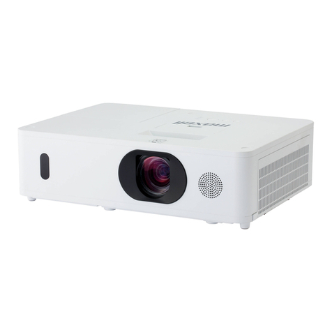
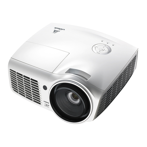
Delta Associate Digital Projection E-Vision 4000 Series Datasheet

Rev A December 2021
E-Vision 4000 Series
High Brightness Digital Video Projector
INSTALLATION & QUICK START GUIDE
CONNECTION GUIDE
OPERATING GUIDE
REFERENCE GUIDE
121-815A

Digital Projection E-Vision 4000 Series Introduction
Introduction
Congratulations on your purchase of this Digital Projection product. Your projector has the following key features:
l4K-UHD projector.
lDisplays 4K-UHD with smooth picture processing.
lUp to 1,300:1 native contrast ratio, and up to 500,000:1 with Advanced Black.
lLong life laser light source
l24/7 Operation
lRec 709 color gamut capability
lHDBaseT® for transmission of uncompressed High Definition Video up to 100 m from the source.
lVertical Keystone geometry correction.
lControl via LAN HDBaseT and RS232.
lAspect Ratio control.
lConstant brightness mode maintains light output at selected levels.
lBuilt in speaker
A serial number is located on the rear of the projector. Please record it here for future reference:
Follow the instructions in this manual carefully to ensure safe and long-lasting use of the projector.
Rev A December 2021
page 2
Introduction
Notes

Aboutthis document Digital Projection E-Vision 4000 Series
About this document
Symbols used in this document
Many pages in this document have a dedicated area for notes. The information in that area is accompanied by the following symbols:
LASER WARNING: this symbol indicates that there is a potential hazard of eye exposure to laser radiation unless the instructions are closely followed.
ELECTRICAL WARNING: this symbol indicates that there is a danger of electrical shock unless the instructions are closely followed.
WARNING: this symbol indicates that there is a danger of physical injury to yourself and/or damage to the equipment unless the instructions are closely followed.
NOTE: this symbol indicates that there is some important information that you should read.
Product revision
Because we at Digital Projection continually strive to improve our products, we may change specifications and designs, and add new features without prior
notice.
Additional Documentation
Updates to this manual may be available online.
Please use the QR code (also located on the projector) to access the latest E-Vision projector user guides and other documentation via the Digital
Projection website.
Or visit the Digital Projection website to download the latest user guide and other documentation.
Legal notice
Trademarks and trade names mentioned in this document remain the property of their respective owners. Digital Projection disclaims any proprietary interest in
trademarks and trade names other than its own.
Copyright © 2021 Digital Projection All rights reserved.
Introduction Rev A December2021
page 3
Notes

Digital Projection E-Vision 4000 Series Electricaland PhysicalSpecifications
Electrical and Physical Specifications
The projector switches to ECO
mode with a reduced light output
when the operating temperature is
between 35°C and 40°C (95°F to
104°F)
Mains Voltage 100-240VAC 50/60Hz 6.0A
Operating Temperature 0°C to 40°C (32°F to 104°F)
Storage Temperature -10°C to 60°C (14°F to 140°F)
Operating Humidity 10% to 85% non-condensing
Storage Humidity 5% to 95% non-condensing
Dimensions L: 405mm (15.94in) X W: 480mm (18.89in) X H: 180mm (7.09in)
Weight 12Kg (26.45lb) including lens
Power Consumption at 100VAC: 570W typical (normal mode)
at 240VAC: 538W typical (normal mode)
Standby Power <0.5W (Network Off), <2W (Network On)
Thermal Dissipation at 100VAC: 1945 BTU/Hour typical (Normal mode)
at 240VAC: 1836 BTU/Hour typical (Normal mode)
Fan Noise 35dBA typical, 37dBA max (Normal mode)
Specifications are subject to change without notice.
Laser Parameters
Wavelength 449-461nm (Blue)
Mode of operation Pulsed, due to frame rate
Pulse duration 1.34ms
Maximum pulse energy 0.698mJ
Rev A December 2021
page 4
Introduction
Notes

Compliance with InternationalStandards Digital Projection E-Vision 4000 Series
Compliance with International Standards
RF Interference
FCC
The Federal Communications Commission does not allow any modifications or changes to the unit EXCEPT those specified by Digital Projection in this manual.
Failure to comply with this government regulation could void your right to operate this equipment.
This equipment has been tested and found to comply with the limits for a Class B digital device, pursuant with Part 15 of the FCC Rules. These limits are
designed to provide reasonable protection against harmful interference when the equipment is operated in a commercial environment. This equipment
generates, uses, and can radiate radio frequency energy and, if not installed and used in accordance with the instruction manual, may cause harmful interference
to radio communications. Operation of this equipment in a residential area may cause harmful interference, in which case the user will be responsible for
correcting any interference.
Noise
GSGV Acoustic Noise Information Ordinance
The sound pressure level is less than 38 dB (A) at normal operating mode according to ISO 3744 or ISO 7779.
European Waste Electrical and Electronic Equipment (WEEE) Directive
Digital Projection Ltd is fully committed to minimizing Waste Electrical and Electronic Equipment. Our products are designed with reuse, recycling and
recovery of all components in mind. To this end, at end of life, your projector may be returned to Digital Projection Ltd or its agent so that the
environmental impact can be minimized.
Introduction Rev A December2021
page 5
Notes

Digital Projection E-Vision 4000 Series Contents
Introduction 2
About this document 3
Symbols used in this document 3
Product revision 3
Additional Documentation 3
Legal notice 3
Electrical and Physical Specifications 4
Laser Parameters 4
Compliance with International Standards 5
RF Interference 5
Noise 5
European Waste Electrical and Electronic Equipment (WEEE) Directive 5
Contents 6
Installation & Quick Start Guide 9
General Precautions 10
What's in the box? 12
Projector overview 13
Location of Laser Aperture 14
Interlock Switches 15
Installation Precautions 16
Laser Safety Precautions 19
Positioning the screen and projector 20
Power Supply 21
AC Power Precautions 21
Connecting the power supply 22
Operating the projector 23
Control panel 23
Projector indicators 24
Remote control 25
Infrared reception 28
Switching the projector on 28
Switching the projector off 28
Interlock reset 29
Selecting an input signal 29
Selecting a test pattern 29
Adjusting the lens 30
Adjusting the image 30
Orientation 30
Geometry 30
Picture 30
Adjusting the audio 31
Connection Guide 33
Signal inputs 34
Digital inputs and outputs 34
EDID on the HDMI, and HDBaseT inputs 35
Using HDMI / HDBaseT switchers with the projector 35
Analog inputs and outputs 36
3D connections 37
3D Sync 37
Control connections 38
LAN connection examples 39
RS232 connection example 40
Operating Guide 41
Using the menus 42
Opening the Menu 42
Exiting menus and closing the OSD 43
Inside the Menu 44
Opening a submenu 44
Editing projector settings 45
Editing numeric values 46
Using the projector 47
Input 47
HDMI 47
Analog 48
3D 48
Picture 49
Advanced 49
Rev A December 2021
page 6
Introduction
Notes
Contents

Contents DigitalProjection E-Vision 4000 Series
White Balance 50
Enhancement 50
Color Manager 51
Alignment 51
Keystone settings 52
Keystone example 53
Network 53
Settings 54
Light Source 55
ECO 55
Menu 56
Security 56
Info 57
Served web pages 58
Reference Guide 61
Appendix A: Product labels 62
Projector 62
Label Locations 64
Appendix B: Screen requirements 65
Fitting the image to the display 65
Images displayed full width of 3840 pixels 65
Images displayed with a height of 2160 pixels 65
Images displayed full height of 2160 pixels 66
Diagonal screen sizes 66
Appendix C: Positioning the image 67
Appendix D: Supported signal input modes 68
2D formats 68
3D formats 70
Appendix E: Wiring details 71
Signal inputs and outputs 71
HDMI 71
HDBaseT input 71
VGA input 72
Control connections 72
LAN 72
RS232 73
Trigger 73
Appendix F: Glossary of terms 74
Introduction Rev A December2021
page 7
Notes

Digital Projection E-Vision 4000 Series
Rev A December 2021
This page is intentionally left blank

Rev A December 2021
E-Vision 4000 Series
High Brightness Digital Video Projector
INSTALLATION & QUICK START GUIDE
121-815A

Digital Projection E-Vision 4000 Series GeneralPrecautions
General Precautions
Warning! Death or Serious Injury could occur if the following precautions are ignored
Eye Hazard! Do not look directly into the lens when the light source is on. The high brightness can cause permanent eye damage
Fire Hazard! Keep any combustible material away from hot surfaces and the projected beam. Ensure cables do not contact hot surfaces
Shock Hazard! Use only authored components, tools, accessories and replacement parts specified by the manufacturer
Trip Hazard! Locate cables where they cannot be pulled, tripped over or damaged by persons or objects
Operate the product in the specified operating environment and conditions
Product should be powered off and disconnected from the mains before any service or maintenance operation
Keep body parts, hair, clothing and jewelery away from moving parts in the product.
Do not operate the product without a lens installed
Use a lens plug when installing or moving the product
The unit is never to be operated if the unit is defective or the cover or seal is damaged.
No maintenance allowed by end user.
Do not open the cabinet. There are no user serviceable parts inside.
No service is allowed except by authorized personnel.
Service personnel should use effective laser safety goggles during service operations.
Use only the power cable provided.
Ensure that the power outlet includes a Ground connection, as this equipment MUST be earthed.
Take care to prevent small objects such as paper or wire from falling into the projector. If this does happen, switch off immediately, and have the
objects removed by authorized service personnel.
Do not expose the projector to rain or moisture, and do not place any liquids on top of the projector.
Unplug before cleaning, and use a damp, not wet, cloth.
Do not touch the power plug with wet hands.
Rev A December 2021
page 10
Introduction
Notes

General Precautions DigitalProjection E-Vision 4000 Series
Do not touch the power plug during a thunder storm.
Handle the power cable carefully and avoid sharp bends. Do not use a damaged power cable.
Do not touch the ventilation outlets, as they will become hot in use.
Do not cover or obstruct the ventilation outlets or inlets.
Do not cover the lens whilst the projector is switched on. This could cause a fire.
Always allow the projector to cool for 5 minutes before disconnecting the power or moving the projector.
Never use strong detergents or solvents such as alcohol or thinners to clean the projector and lens.
Introduction Rev A December2021
page 11
Notes

Digital Projection E-Vision 4000 Series What's in the box?
What's in the box?
Make sure your box contains
everything listed. If any pieces are
missing, contact your dealer.
Only one remote is supplied with
the projector.
Save and store the original box and
packing materials, in case you ever
need to ship your projector.
Only the appropriate cable for
destination territory is supplied with
the projector
Projector
Remote Control Batteries (2xAAA)
Important Information Book
Power Cable, UK Power Cable, Europe Power Cable, China NEMA 5-15P - C13 Power Cable, North America
3 Pin to BNC Adapter Cable HDMI Cable
Rev A December 2021
page 12
Introduction
Notes

Projector overview Digital Projection E-Vision 4000 Series
Projector overview
See Product labels on page62 for
details about the labels that are
located on the projector.
7
8
9
10
Rear View
1
2
3
4
5
6
Front View
11
Bottom View
1. Front infrared window
2. Zoom control
3. Focus control
4. Lens shift controls
5. Indicators
6. Air outlet
7. Control panel
8. Air inlet
9. Connections panel
10. Mains socket
11. Adjustable feet
Installation & QuickStartGuide Rev A December 2021
page 13
Notes

Digital Projection E-Vision 4000 Series Projector overview
Location of Laser Aperture
1
1. The laser aperture is located as indicated below.
Do not look directly at the light coming from the lens.
Rev A December 2021
page 14
Installation & QuickStartGuide
Notes

Digital Projection E-Vision 4000 Series
Interlock Switches
1
Interlock switches are installed inside the projector. These will power-off the system when
activated.
1. Will be activated when the top cover is removed.
Introduction Rev A December2021
page 15
Notes

Digital Projection E-Vision 4000 Series Installation Precautions
Installation Precautions
The projector must be installed only by suitably qualified personnel, in accordance with local building codes.
The projector is heavy. Use safe handling techniques when lifting the projector.
Do not drop or knock the projector.
Do not install the projector close to anything that might be affected by its operational heat, for instance, polystyrene ceiling tiles, curtains etc.
Place the projector in a dry area away from sources of dust, moisture, steam, smoke, sunlight or heat.
Ensure that the intake vents do not recycle hot air from the exhaust vent.
When operating the projector in an enclosed space, ensure that the surrounding air temperature within the enclosure does not exceed operation
temperature while the projector is running, and the air intake and exhaust vents are unobstructed.
All enclosures should pass a certified thermal evaluation to ensure that the projector does not recycle exhaust air, as this may cause the device to
shutdown even if the enclosure temperature is with the acceptable operation temperature range.
Avoid installing at high temperature, insufficient cooling and heavy dust locations.
Keep your product away from fluorescent lamps (>1 Meter) to avoid malfunction caused by IR interference.
Avoid installing near an air conditioner duct or a subwoofer.
The projector should be installed as close to the power outlet as possible.
The power connection should be easily accessible, so that it can be disconnected in an emergency.
Please pay attention to projector installation with respect to other staging laser light equipment set-up. These systems can cause permanent
damage to the DMD imaging devices used in our projectors. This damage is not covered by our warranty.
When using projectors in environments with third party high power laser systems avoid direct laser beams pointing towards the projection lens.
This may cause incident light to converge into the optical engine and cause damage to the DLP DMD.
Before installation, make sure that the surface, ceiling or rigging that is to support the projector is capable of supporting the combined weight of
the projector and lens.
Backup safety chains or wires should always be used with ceiling mount installations.
When installing a ceiling mount, make sure the weight limit is not exceeded and the projector is firmly secured.
Rev A December 2021
page 16
Installation & QuickStartGuide
Notes

Installation Precautions Digital Projection E-Vision 4000 Series
The projector can be operated any position, as shown in the diagram:
360˚
360˚
Tilt (Left) and Roll (Right)
Allow at least 50cm (19.7in) of space between the ventilation outlets and any wall, and 30cm (11.8in) on all other sides.
Minimum 500mm
(19.69in)
Minimum 500mm
(19.69in)
Minimum 500mm
(19.69in)
Minimum 100mm
(3.94in)
Minimum 500mm
(19.69in) Minimum 300mm
(11.81in)
Example Positioning
Installation & QuickStartGuide Rev A December 2021
page 17
Notes

Digital Projection E-Vision 4000 Series Installation Precautions
Make sure the lens cap is removed from the lens before operating the projector. Light energy levels have been known to cause damage to both the
lens and projector optics. This damage is not covered by our warranty.
Connect the LAN cable only to a computer LAN connection. Other similar connectors may have a dangerously high voltage source.
A VGA IN connector should be used to connect to the VGA IN port on the projector. It should be inserted tightly, with the screws on both sides
securely fastened to ensure proper connection of the signal wire for achieving optimal display effect.
An AUDIO IN connector should be used to connect to the AUDIO IN port on the projector.
The power cord and signal cable should be connected before the projector is powered on. During startup and operation, DO NOT insert or remove
the signal cable or the power cord to avoid damaging the projector.
The projector generates heat during use. The internal fans dissipate the heat of the projector when shutting down, which could continue for a
certain period. After the projector enters STANDBY MODE, remove the power cord. DO NOT remove the power cord during shutdown as it may
cause damage to the projector and may affect the service life of the projector.
Do not place heavy objects on top of the projector chassis.
Rev A December 2021
page 18
Installation & QuickStartGuide
Notes

LaserSafety Precautions Digital Projection E-Vision 4000 Series
Laser Safety Precautions
See Product labels on page62 for
details about the labels that are
located on the projector.
Warning! Death or Serious Injury could occur if the following precautions are ignored
Permanent/Temporary Blindness Hazard
Class 1 RG2 Laser Product. Caution! Do not stare into beam. Class 1 IEC 60825-1:2014, RG2 IEC 62471-5:2015.
The product should be installed and operated in accordance with the provisions of IEC 62471-5:2015 and the Important Information document or
User Manual
Caution – use of controls or adjustments or performance of procedures other than those specified herein may result in hazardous radiation
exposure.
Do not attempt to operate the product without covers in place.
Do not look directly into the lens when the light source is on. The high brightness can cause permanent eye damage.
Installation & QuickStartGuide Rev A December 2021
page 19
Notes

Digital Projection E-Vision 4000 Series Positioningthe screen and projector
Positioning the screen and projector
Always allow the projector to
cool for 5 minutes before
disconnecting the power or
moving the projector.
Ensure that there is at least 50
cm (19.7 in) of space between
the ventilation outlets and any
wall, and 30 cm (11.8 in) on all
other sides.
Do not use the threaded holes
for the adjustable feet to hang
or mount the projector.
Avoid extending the adjustable
feet to the limit of the thread.
1. Install the screen, ensuring that it is in the best position for viewing by your audience.
2. Mount the projector, ensuring that it is at a suitable distance from the screen for the image to fill the screen. Set the adjustable feet so that the projector is
level, and perpendicular to the screen.
1
1
2
2
The drawing shows the positions of the feet for table mounting, and the fixing holes for ceiling
mounting.
1. Two adjustable feet
1
.
2. Four M4 holes for ceiling mount
2
.
The screws should not penetrate more than 8 mm into the body of the projector.
Rev A December 2021
page 20
Installation & QuickStartGuide
Notes
Table of contents
Other Delta Associate Projector manuals
Delta Associate
Delta Associate DIGITAL PROJECTION E-Vision Laser 9000... Operating manual
Delta Associate
Delta Associate DIGITAL PROJECTION E-VISION LASER 5900... User manual
Delta Associate
Delta Associate Digital Projection E-Vision Laser 13000 WU Operating manual
Delta Associate
Delta Associate Digital Projection Titan Laser Series Operating manual
