-2-
Contents
SERVICE MANUAL ................................................... 1
Contents ........................................................................ 2
Safety Instructions......................................................... 3
Safety Precautions ..................................................... 3
Product Safety Notice................................................. 3
Service Personnel Warning........................................ 3
Specifications ................................................................ 4
Circuit Protections ......................................................... 5
Fuse............................................................................ 5
Thermal protectors (SW902) ...................................... 5
Mechanical sensor switches (SW901, SW1891)......... 6
Temperature sensors, wind sensors........................... 7
Power failure and fan lock detection........................... 8
Maintenance.................................................................. 9
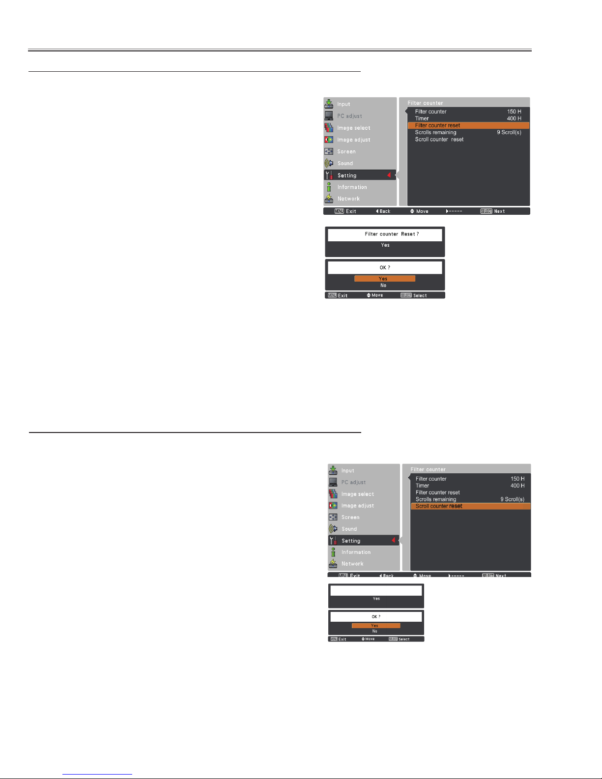
Replacing the Filter Cartridge..................................... 9
Lamp Replacement ...................................................11
How to check Lamp Used Time ............................... 12
Quick maintenance................................................... 13
Lens Installation........................................................ 14
Using the Lens Antitheft screw................................. 15
Cleaning ................................................................... 16
Cleaning the Projection Lens ................................... 16
Cleaning the Projector Cabinet................................. 16
Security Function Notice ............................................. 17
Mechanical Disassembly............................................. 18
Optical Parts Disassembly .......................................... 27
Adjustments................................................................. 33
Adjustments after Parts Replacement...................... 33
Note on Main Board Replacement ........................... 33
Service Adjustment Menu Operation ....................... 34
Optical Adjustment ...................................................... 35
1. Optical axis adjustment ........................................ 36
2. Contrast adjustment ............................................. 40
Electrical Adjustments................................................. 41
Circuit Adjustments................................................... 41
Test Points and Locations ........................................ 45
Service Adjustment Data Table ................................ 46
Troubleshooting ........................................................... 66
Chassis over view..................................................... 66
No Power.................................................................. 67
No Power (Power supply) ......................................... 68
No Power (Power supply) ......................................... 69
No Power (Fan control)............................................. 70
No Power (Lamp control).......................................... 71
Temperature Abnormality ......................................... 72
No Picture................................................................. 73
No Sound.................................................................. 74
Motor control problems............................................. 75
Bus control................................................................ 76
LED drive & RC control ........................................... 77
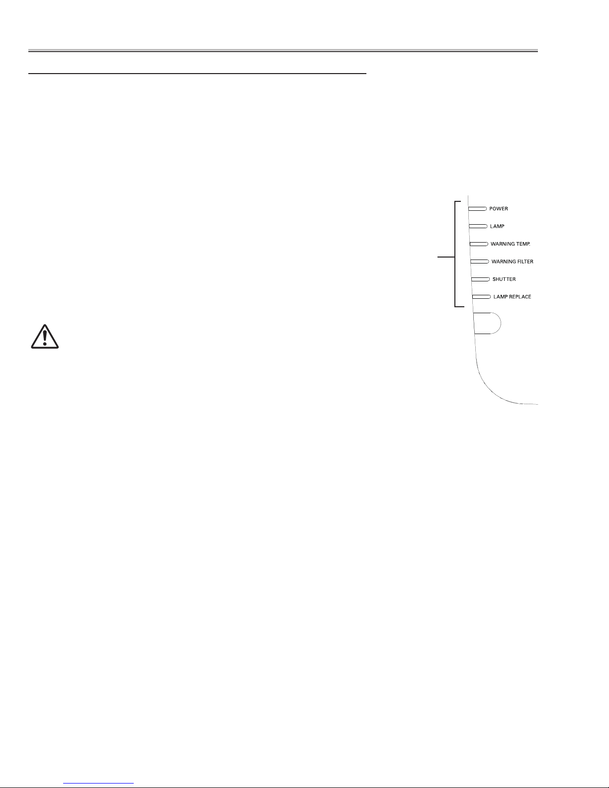
Indicators and Projector Condition ........................... 78
Power failure detection system ................................ 81
Diagnosis of Power Failure with RS-232C port ........ 85
Serial Control Interface............................................. 86
Control Port Functions................................................. 88
IC Block Diagrams....................................................... 91
Parts Location Diagrams........................................... 101
Mechanical Parts List .................................................110
Electrical Parts List.....................................................112
Diagrams & Drawings.................................................. A1
Parts description and reading in schematic diagram ..A2
Schematic Diagrams ...................................................A3
Printed Wiring Board Diagrams................................. A15
Pin description of diode, transistor and IC................. A19
Note on Soldering......................................................A20