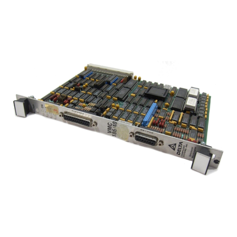
Delta Computer Systems TMC 188/40 Series User manual

TMC 188/40 Rev 4.1
Motion Control Module
960912
Delta Computer Systems, Inc.
1818 SE 17th Street
Battle Ground, WA 98604
Tel: 360/254-8688
Fax: 360/254-5435
http://www.deltamotion.com

Although great effort has been taken to ensure the accuracy of the information in this document, it is
intended to be used only as a guide. Knowledge of motion control, hydraulic servos, electric servos,
magnetostrictive displacement transducers, and safety rules is required. Delta Computer Systems,
Inc. cannot accept responsibility for problems resulting from omissions in this document. The
information in this document is subject to change without notice.
Neither Delta Computer Systems, Inc. nor anyone else involved in the creation, production, or
delivery of this product shall be liable for any direct, indirect, consequential injuries and or damages
arising out of the use, the results of use, or the inability to use this product.
All brand names and trademarks referenced in this manual are the property of their respective
holders.
© 1996 Delta Computer Systems, Inc. Vancouver, WA
Printed in USA

Contents
Delta Computer Systems, Inc. 360/254-8688 3
OVERVIEW ............................................................................................................................................ 7
HARDWARE SPECIFICATIONS...........................................................................................................8
GETTING STARTED AND TUNING THE AXIS ....................................................................................9
STEP 1-CONFIGURING THE TMC MODULE........................................................................................9
STEP 2-CONFIGURING THE P/C BASE...............................................................................................9
STEP 3-INITIALIZING THE WYREGISTERS .........................................................................................9
STEP 4-SELECTING THE APPROACH ...............................................................................................10
STEP 5-SETTING UP THE INITIALIZATION PARAMETERS....................................................................10
STEP 6-MOVING THE AXIS USING DCSMON..................................................................................12
STEP 7-JOGGING THE AXIS ............................................................................................................13
STEP 8-TUNING THE AXIS ..............................................................................................................14
P/C PROGRAMMING PRECAUTIONS...............................................................................................15
P/C ERROR HANDLING....................................................................................................................15
KEY THINGS TO REMEMBER.............................................................................................................15
WY REGISTER AND V MEMORY IMAGE DESCRIPTIONS..............................................................16
WYREGISTERS ..............................................................................................................................16
AXIS INITIALIZATION PROCESS .........................................................................................................17
VINIT AXIS INITIALIZATION PARAMETERS .........................................................................................18
VREAD -AXIS POSITION AND STATUS PARAMETERS........................................................................19
VWRITE -AXIS DYNAMIC CONTROL PARAMETERS...........................................................................20
VMEMORY EXAMPLE ......................................................................................................................21
MOTION CONTROL PARAMETERS..................................................................................................23
READ ONLY PARAMETERS (VREAD) ...............................................................................................23
INITIALIZATION PARAMETERS (VINIT)...............................................................................................27
DYNAMIC CONTROL COMMANDS (VWRITE).....................................................................................33
HOW IT WORKS..................................................................................................................................43
INITIALIZATION.................................................................................................................................43
PARAMETER USE ............................................................................................................................43
POSITION SENSING .........................................................................................................................43
DRIVE OUTPUT ...............................................................................................................................43
CLOSING THE LOOP.........................................................................................................................44
PROPORTIONAL GAINS ....................................................................................................................44
INTEGRAL AND DIFFERENTIAL GAINS ................................................................................................44
FEED FORWARD..............................................................................................................................45
CONTROL AT REST..........................................................................................................................45
MODULE HARDWARE........................................................................................................................46
FRONT PANEL INDICATORS..............................................................................................................46
MODULE JUMPERS AND EXTERNAL WIRING ......................................................................................47
FAIL-SAFE TIMERS..........................................................................................................................50
SYSTEM RESET...............................................................................................................................51
CABLE &CONNECTOR INFORMATION................................................................................................51
COMMON PROBLEMS AND SOLUTIONS ........................................................................................53
LADDER PROGRAM CANNOT ACCESS PARAMETERS OR OPERATE MODULE...........................................53
DURING A MOVE,THE ACTUAL POSITION IS ERRATIC....................................................................53
TRANSDUCER COUNTS FIELD NOT INDICATING TRANSDUCER LOCATION.......................................53
TRANSDUCER COUNTS FIELD CHANGES BUT OUTPUT DRIVE DOES NOT WORK..............................53

Delta Computer Systems, Inc. 360/254-8688
4
AXIS INDICATOR IS CONSTANT RED....................................................................................................54
DURING A MOVE,THE AXIS COMES TO A HALT FOR NO APPARENT REASON...........................................54
HYDRAULIC SYSTEM PROBLEMS....................................................................................................55
NONLINEAR VALVES.........................................................................................................................55
SLOW-RESPONSE VALVES ...............................................................................................................55
HOSES............................................................................................................................................55
PUMPS AND ACCUMULATORS ...........................................................................................................56
IDENTIFICATION AND CORRECTION....................................................................................................56
REPAIRS AND RETURNS...................................................................................................................59
FIELD REPAIR OF A MODULE ............................................................................................................59
DELTA BULLETIN BOARD SYSTEM.....................................................................................................59
MODULE RETURNS ..........................................................................................................................59
GLOSSARY..........................................................................................................................................60
APPENDIX A: MAPS, TIPS, AND COMMANDS.................................................................................61
STATUS WORD BIT MAP...............................................................................................................61
MODEWORD BIT MAP..................................................................................................................62
EXAMPLE VMEMORY MAP...............................................................................................................63
QUICK-START GUIDE.......................................................................................................................64
AXIS TUNING TIPS ...........................................................................................................................69
DCSMON COMMAND SUMMARY......................................................................................................71
CONTROL EQUATIONS......................................................................................................................73
ASCII CODE CHART........................................................................................................................74
APPENDIX B: ASBX/40 ANALOG MODULE......................................................................................75
DESCRIPTION ..................................................................................................................................75
INSTALLATION..................................................................................................................................75
SPECIFICATIONS..............................................................................................................................75
VREAD VMEMORY ........................................................................................................................75
NEW VREAD PARAMETER DEFINITIONS...........................................................................................77
VINIT VMEMORY............................................................................................................................77
NEW VINIT PARAMETER DEFINITIONS ..............................................................................................78
MODE AND STATUS WORD CHANGES..........................................................................................79
PRESSURE-SPECIFIC COMMANDS.....................................................................................................79
ASBX/40 SETUP...........................................................................................................................80
SETTING THE PRESSURE SCALE AND PRESSURE OFFSET.......................................................81
USING THE TMC 188/40-TA............................................................................................................81
PRESSURE PLOTS ...........................................................................................................................82
CONNECTOR ...................................................................................................................................82
APPENDIX C: QSBX/40 QUADRATURE MODULE ...........................................................................83
INTRODUCTION ................................................................................................................................83
QSBX/40 SPECIFICATIONS..............................................................................................................83
QSBX/40 BLOCK DIAGRAM..............................................................................................................84
IMPORTANT CONSIDERATIONS WHEN USING QUADRATURE ENCODERS..............................................84
QUADRATURE ENCODER POSITION MEASUREMENT...........................................................................86
QUADRATURE ENCODER-SPECIFIC COMMANDS ................................................................................87
TMC 188/40-(T)Q PARAMETER CHANGES .......................................................................................89
READBACK PARAMETERS.................................................................................................................91
LIMIT AND HOME DIGITAL INPUTS......................................................................................................92
QSBX/40 BOARD JUMPERS.............................................................................................................94
QUADRATURE ENCODER INTERFACE EXAMPLES................................................................................95

Delta Computer Systems, Inc. 360/254-8688 5
FRONT PANEL INDICATORS..............................................................................................................96
FRONT PANEL DB 37 FEMALE CONNECTOR .....................................................................................97
SAMPLE LIMIT AND HOME CONFIGURATION.......................................................................................98
APPENDIX D: APPLICATION NOTES................................................................................................99
USING THE OFFSET AND DIRECTION FIELDS................................................................................99
ACCELERATION AND DECELERATION MODES ..................................................................................101
EVEN ENDING...............................................................................................................................102
EXAMPLE USING 20MASERVO VALVES WITH 100MAOUTPUT.........................................................103
APPENDIX E: SAMPLE LADDER LOGIC.......................................................................................104
TMC 188/40 WIRING DIAGRAMS.....................................................................................................108
INDEX.................................................................................................................................................109

Delta Computer Systems, Inc. 360/254-8688
6

TMC 188/40 Motion Control Module Overview
Delta Computer Systems, Inc. 360/254-8688 7
Overview
The TMC 188/40 family of Motion Control Modules provides a complete four-axis position control
subsystem for the Siemens SIMATIC TI505 system. The module controls the axes by providing a
complete PID loop plus many additional functions, such as on-the-fly coordinated moves and position
changes. In its standard configuration the module provides four optically isolated magnetostrictive
interfaces and four optically isolated outputs, each individually configurable for voltage or current
mode. A variety of output configurations work with electric servo motors and hydraulic valves. With
the Quadrature and Analog options installed, you can control position using either quadrature
encoders, analog slide potentiometers, or pressure.
The TMC 188/40 Motion Control Module (MCM) occupies one slot of the SIMATIC TI505 rack (two
slots if the Analog or Quadrature options are installed). A Special Function Interface Chip (SFIC)
communicates between the SIMATIC TI505 programmable controller (P/C) and the TMC 188/40. The
TMC 188/40 is programmed using V Memory and eight SFIC WY registers. The on-board 80C188
processor relieves the P/C of the overhead usually associated with servo control. The MCM updates
the actual position and drive output every two milliseconds, assuring accurate positioning even at
high speed.
If you need more than four axes of control you can install additional TMC 188/40 modules.
TMC 188/40 System Block Diagram
NOTE: Increase in P/C scan times (per module installed) when using the TMC 188/40 are:
525 10 ms per module (not including P/C or remote overhead)
535 1.6 ms
545 0.8 ms
If the TMC 188/40 is used on a remote base, the P/C scan time will degrade considerably.

Overview TMC 188/40 Motion Control Module
Delta Computer Systems, Inc. 360/254-8688
8
Hardware Specifications
TMC 188/40
One slot of SIMATIC TI505 chassis (two slots when ASBX or QSBX options are installed)
13.875MHz 80188 processor
SFIC Interface
2 millisecond control loop time.
Linear resolution to 0.001 inches
Maximum velocity - 60,000 position units per second
Maximum position counts - 65535
Three hardware fail-safe timers
Standard Position Inputs
Four optically isolated magnetostrictive transducer interfaces
Field-replaceable transducer protection resistors for Temposonics® I and
Temposonics® II neuter transducers
1.5V return pulse sensitivity
27.75MHz counters
1, 2, or 4 recirculations
Positive or negative interrogation pulse
Maximum update rate - 2 milliseconds
Drive Four optically isolated, individually configurable servo drive outputs
Current mode: ±100mA, ±50mA, or ±25mA
Voltage mode: ±10 volts, ±5 volts, or ±2.5 volts
12 bit digital to analog converters
Power Requirements
5V
@ 1.0 amps
TI System Bus
5V
@ 0.5 amps
External Sensor
15V
@ 0.5 amps
External Sensor
If transducers are connected to the
-15V
@ 0.5 amps
External Sensor
module; 0.1A for module only.
15V
@ 0.5 amps
External Drive
0.1A for module + max current
-15V
@ 0.5 amps
External Drive
for axes used. Voltage mode uses
zero added current per axis.
All power supply voltages must be within 5% of the specified voltage.
Sensor power supplies should be independent of drive power supplies.

TMC 188/40 Motion Control Module Getting Started
Delta Computer Systems, Inc. 360/254-8688 9
Getting Started and Tuning the Axis
CAUTION: When starting the Motion Control Module for the first time, great care must be taken to avoid
accidents. The most common accident is a runaway. This is where the MCM tries to move the
axis to a position beyond it's physical limits.
MAKE SURE THE POWER TO THE DRIVE IS TURNED OFF
BEFORE STARTING THIS PROCEDURE!
Step 1 - Configuring The TMC Module
To configure the TMC module so it will work with your system, the following five steps must be taken.
See Module Jumpers and External Wiring (on page 47) and TMC Wiring Diagrams (on page 107)
for details about these steps.
1. Select voltage or current mode for the drive output of each axis (Default: current mode).
2. Select the drive level for each axis (Default: 50mA; range: 25, 50, 100mA or 2.5, 5, 10 volts)
3. Individually select each transducer interrogation pulse polarity (Default: Positive; Negative is
for short Temposonics® I rods only).
4. Individually select the number of recirculations used on each axis (Default: 4; Range: 1, 2, 4).
5. Wire the transducer and drive cables to your system.
Step 2 - Configuring the P/C Base
To configure the P/C so it will communicate with the TMC 188/40, the appropriate slot in the Base
must be initialized. To configure the P/C Base:
1. Run TISOFT software.
2. Put it in the ONLINE mode.
3. Enter the CONFIO menu.
4. Verify the appropriate slot is configured for eight WY registers with SPECIAL FUNCTION
capability. This can be done manually or by doing a READBS.
5. Set the I/O address so it will not conflict with other I/O in the system. (The programs supplied
with DCSMON use WY201 through WY208. DCSMON is a monitor program included with
each Motion Control Module. See the DCSMON manual for more information.)
6. Update the information in the P/C by doing a WRITPC.
7. Initialize the WY registers as described in the next section.
Step 3 - Initializing the WY Registers
The eight WY registers must be initialized before the TMC 188/40 will begin normal operation. The
WY registers define the P/C's V Memory locations where the TMC 188/40 reads and writes
information. The initialization can be done either with the CHART utility of TISOFT or with a ladder
logic routine (see filelist.txt on the DCSMON disk for example ladder programs).

Getting Started TMC 188/40 Motion Control Module
Delta Computer Systems, Inc. 360/254-8688
10
The following example shows you how to initialize the WY registers. The values are the same as
those in the demo program.
WY Register
Value
(V Memory Address)
Definition
WY201
201
VINIT Axis 1
WY202
251
VINIT Axis 2
WY203
301
VINIT Axis 3
WY204
351
VINIT Axis 4
WY205
401
VREAD
WY206
451
VWRITE
WY207
0
Reserved
WY208
1956
Checksum
(201+251+301+...)
To set up the WY registers:
1. Run TISOFT.
2. Put it in the ON-LINE mode.
3. Select CHART; select BLDCHT.
4. Enter WY201 - WY208 (or whatever WY registers you are going to use).
5. Select CHGVAL to set the values for the eight WY registers. The values you enter are the
addresses of the V Memory locations which the TMC 188/40 talks to (201, 251, etc. in the
demo program).
6. When you have entered all eight values (including the checksum), verify the P/C LED on the
TMC 188/40 panel is green.
NOTE: Once the TMC 188/40 finds a correct set of WY registers (including a valid checksum), it will not
read them again unless reset. Changes in the WY registers will not take effect until the TMC
188/40 is reset or the power is cycled.
Step 4 - Selecting the Approach
Once the WY registers are initialized, there are two methodss to get the TMC 188/40 running. The
first is to use DELTA's PC-based program called DCSMON. DCSMON provides a simple way for you
to get on-line without using a P/C ladder logic program. DCSMON talks directly to the TMC 188/40
by using the P/C's store and forward commands. Please refer to the DCSMON manual for help using
it.
The second method is for you to follow the steps outlined below. To help you start, an example
program is provided with DCSMON. The latest versions of this demo program are listed in filelist.txt
on the DCSMON disk. You can use it with the 525, 535, 545, and 555 controllers after the controller
type is specified using TISOFT.
TIP: Use Delta's DCSMON to help determine initialization parameters and operation. Also, Delta's
SSS/10 Servo System Simulator provides a simple way to test your program before connecting
the Motion Control Module to your system.
Step 5 - Setting Up the Initialization Parameters
When the TMC 188/40 Motion Control Module is first turned on, default values are used for the
initialization parameters. These values are there only to give the MCM so the present position can be
maintained. The parameters need to be changed to work optimally in your system. The P/C is

TMC 188/40 Motion Control Module Getting Started
Delta Computer Systems, Inc. 360/254-8688 11
responsible for initializing the parameters when the TMC 188/40 is powered up. It must place the
correct values in the Special Function Interface Chip (SFIC) WY registers, write the parameter values
to V Memory, and issue a 'P' command to the MCM. The following procedure will help you determine
the optimal values for the initialization parameters.
First, disconnect the drive output from the TMC 188/40 (15 pin connector), and find a way to move
the axis by hand. Build a chart in TISOFT (or use the chart on the DCSMON disk) to monitor the
appropriate V Memory locations (see the sample V Memory map on pages 21 ans 22). Make sure
the transducers are connected and powered.
If you want to begin quickly, you can proceed to Step 6 - Moving The Axis. Continue with this section
now or return to it later to set the DIRECTION, SCALE, and OFFSET parameter values.
DIRECTION Parameter
Decide whether the ACTUAL POSITION will increase or decrease as the axis extends. (Remember -
extending is the direction that returns increasing TRANSDUCER COUNTS.) The DIRECTION
parameter should be 0 if the ACTUAL POSITION increases as the axis extends, and it must be zero
for Quadrature applications (see Appendix C). This is the default value. The DIRECTION parameter
should be set to -1 (0FFFFH) only if the ACTUAL POSITION decreases when the axis extends.
Next, have the P/C issue 'P' command (80D, 50H) in the VWRITE COMMAND field
SCALE Parameter
The SCALE parameter is used to convert the transducer or encoder counts to position units. For
magnetostrictive transducers (MDT), compute the SCALE as follows (see pages 30-31 for examples):
32768 x Position Units per inch
SCALE =
MDT Cal Number(in microseconds per inch) x 27.75MHz x Number of Recirculations
TIP: Delta's DCSMON provides an easy way to work with SCALE. Use DCSMON's commands P0 and
P1 to help calculate SCALE , OFFSET, DIRECTION, and EXTEND and RETRACT LIMITS.
For Analog and Quadrature options, see the respective appendix for SCALE information.
OFFSET Parameter
Next, the axis OFFSET must be set. The axis OFFSET is added to the position of the axis before it is
stored in the ACTUAL POSITION of V Memory. When you change the OFFSET, make sure to
change the EXTEND LIMIT and RETRACT LIMIT by the same amount. Use the following equation to
adjust the current ACTUAL POSITION:
OFFSET = Old OFFSET + Desired Position - ACTUAL POSITION
If the OFFSET is greater than 32767, subtract 65536 from the OFFSET. If the OFFSET is less than
-32768, add 65536 to the OFFSET. When the OFFSET is changed, both the EXTEND and
RETRACT limits must be adjusted accordingly. Send an Alt-P to initialize the new values. Check by
moving the axis to the extend and retract limits and make any adjustments necessary.
NOTE: 1) Do not use the OFFSET parameter to compensate for severe mechanical misalignment. The
physical system must be aligned before the OFFSET parameter is adjusted.
2) After adjusting the DIRECTION, SCALE and OFFSET, be sure to adjust the EXTEND and
RETRACT LIMITS as described below. See Appendix D for more information.

Getting Started TMC 188/40 Motion Control Module
Delta Computer Systems, Inc. 360/254-8688
12
Step 6 - Moving the Axis Using DCSMON
With the axis drive output still disconnected and the transducers on, manually move the axis close to
the physical extend limit; be sure to leave some space for error. (Remember: Extending is the
direction that returns increasing TRANSDUCER COUNTS.) If you are using DCSMON, be sure you
are in Write mode rather than Read mode (a „W‟ rather than an „R‟ in the lower right corner of the
DCSMON main screen; press Ctrl-T to toggle the mode). In Read mode the parameters will not be
written to V Memory and will be lost on power-down. Enter the ACTUAL POSITION reading as the
value for the EXTEND LIMIT parameter. Now move the axis close to the physical retract limit and set
the RETRACT LIMIT parameter. Issue a 'P' command.
If you cannot move the axis manually, the following procedure uses DCSMON and the open loop
mode to slowly move the axis.
CAUTION - OPEN LOOP OPERATION IGNORES ALL LIMITS! BE PREPARED TO REMOVE DRIVE
POWER!
A. Connect the TMC drive output to the valves.
B. In DCSMON, with the cursor on the axis you want to adjust, enter Alt-R to restore the null. Put
0 (zero) in the REQUESTED POSITION field, enter Alt-Shift-O, and verify that DRIVE = 2048.
C. Turn on the hydraulics (the axis will drift due to valve null errors).
D. Put 100 in the REQUESTED POSITION field and enter Alt-Shift-O, then put 0 (zero)in the
REQUESTED POSITION field. Verify that DRIVE = 2148. The axis should extend. If the axis
retracts, check the drive wiring polarity, hydraulic plumbing, and the value null. Correct any
problems before continuing.
E. When the axis gets to the extend limit, enter Alt-Shift-O, then Alt-P to stop the axis. Enter the
ACTUAL POS. value in the EXTEND LIMIT parameter.
F. Put -100 in the REQUESTED POSITION field and enter Alt-Shift-O, then put 0 (zero) in the
REQUESTED POSITION field. Verify that DRIVE = 1948. The axis should retract.
G. When the axis gets to the retract limit, enter Alt-Shift-O, then Alt-P to stop the axis. Enter the
ACTUAL POS. value in the RETRACT LIMIT parameter.
H. Repeat Steps B through G for each axis in use.
For each axis you‟ll be using, set the following parameter and profile terms to the indicated values,
then press Alt-P on each axis. This will initialize the axis with any changes. (A HALT MASK of
0EFFF hides all errors except OVERDRIVE.)
Parameter terms:
HALT MASK 0EFFF
FEED FWD ADV 0
NULL UPDATE 0
DITHER 0
HYSTERESIS 0
PRO STAT GAIN 5
PRO EXT GAIN 5
PRO RET GAIN 5
INTEGRAL GAIN 0
DIFFER GAIN 0
EXT. FEED FWD. 100
RET. FEED FWD. 100
Profile terms:
MODE 00001
ACCEL 1% of SPEED
DECEL 1% of SPEED
SPEED 20% of maximum system
speed (1000 = 1 in/sec)

TMC 188/40 Motion Control Module Getting Started
Delta Computer Systems, Inc. 360/254-8688 13
NOTE: Do not use the INTEGRAL or DIFFERENTIAL GAINS or FEED FORWARD ADVANCE until you
have finished with steps 1 to 10 in Tuning the Axis. Leave them at their defaults.
Turn off the power to the TMC 188/40 and connect the drive output (if you haven‟t already done so).
Turn the power back on and issue a 'P' command to each axis you are using. Make several short
slow moves by entering the REQUESTED POSITION and issuing a GO ('G') command.
TIP: DCSMON is very useful. We recommend using it to troubleshoot and tune the system. It
provides dynamic move information in graphic form.
Increase the speed and accelerations gradually while making longer moves. After a move press
INSERT to make a graph of that move, then look for LEAD, LAG, overshoot, or oscillation. Eventually
you will reach a speed or acceleration which will cause an error on the axis.
There are three errors to be concerned with at this time. If an overdrive error occurs (green line going
to the top or bottom of the screen and axis halted), there is not enough drive capacity to drive the axis
at the requested speed. If this occurs, reduce the SPEED. If a LAG error occurs (press Ctrl-B to
display the status bits), the appropriate feed forward must be increased. If a LEAD error occurs, the
appropriate feed forward must be decreased. In either case, you can enter an 'Alt-F' from DCSMON
or an 'F' command from the P/C ladder program to automatically adjust the feed forward terms. If this
does not solve the problem, the acceleration and deceleration ramps are too steep for the response
of the system; the ramp distance should be increased.
After the problem causing the error has been corrected, continue to increase the speed and move the
axis until you reach the desired speed. Should the system seem a little sloppy, try decreasing the
MAXIMUM POSITION ERROR and adjusting one of the system gains (STATIC, EXTEND and
RETRACT) until the axis can be moved without getting an error. Remember, the parameters are not
updated in the TMC 188/40 until the 'P' command is issued on each axis.
Step 7 - Jogging the Axis
You can jog the axis by setting the REQUESTED POSITION to the EXTEND LIMIT or RETRACT
LIMIT, then using the 'G' and 'H' commands repeatedly. This causes the MCM to GO then HALT.

Getting Started TMC 188/40 Motion Control Module
Delta Computer Systems, Inc. 360/254-8688
14
Step 8 - Tuning the Axis
Use Delta's DCSMON program so you can change parameters and graph the moves during the
tuning process. At this point you should be able to make slow moves without errors (no red axis LEDs
on the TMC front panel).
It will probably be necessary to mask off several bits in the HALT MASK while tuning the system to
avoid stopping every time an error occurs (see page 27 for HALT MASK information).
1) If the axis oscillates when it shouldn't be moving, reduce the STATIC GAIN.
2) If the axis oscillates when it is extending, reduce the EXTEND GAIN.
3) If the axis oscillates when it is retracting, reduce the RETRACT GAIN.
4) Gains should be increased until the axis starts to oscillate, then follow tips 1 through 3.
5) If the axis gets a LEAD error and no LAG error while extending, reduce the EXTEND FEED
FORWARD.
6) If the axis gets a LAG error and no LEAD error while extending, increase the EXTEND FEED
FORWARD.
7) If the axis gets a LEAD error and no LAG error while retracting, reduce the RETRACT FEED
FORWARD.
8) If the axis gets a LAG error and no LEAD error while retracting, increase the RETRACT FEED
FORWARD.
9) If the axis gets both a LAG error and a LEAD error, check for oscillations (tips 2 & 3). If it is not
oscillating, increase the MAX ERROR until you get only one error (tips 5 - 8). Also check the
FEED FORWARD ADVANCE (tip 14).
10) Once the axis moves smoothly, use the 'F' command (automatic tuning).
11) If the axis hunts around the set point, increase the HYSTERESIS gradually until the hunting
stops or the axis starts to oscillate. If oscillations occur, reduce the HYSTERESIS.
12) The NULL UPDATE should not be used until the HYSTERESIS is adjusted. Try to keep the
NULL UPDATE interval value higher than 1000. Systems with fast response times require
larger NULL UPDATE intervals.
13) If the axis gets no LAG or LEAD errors, reduce the MAX ERROR until errors start to occur then
either tune the axis some more (tips 5 - 8), or increase the MAX ERROR a little.
14) The FEED FORWARD ADVANCE must be the same for all synchronized axis. Increasing the
FEED FORWARD ADVANCE will decrease the chance of getting a LAG error when ramping up
or getting a LEAD error while ramping down. If the FEED FORWARD ADVANCE is too high,
the axis will LEAD when ramping up and LAG when ramping down.
15) The INTEGRAL GAIN is useful only when the feed forward terms cannot correct a problem.
This may occur if the upper limit of the feed forward is reached or the axis has a nonlinear
response to drive output. If the axis requires a different feed forward to move 10 inches a
second than when moving 20 inches a second, the axis is nonlinear and the integrator can help
compensate. In these cases a little integral gain will do the job.
16) Another problem occurs on moves of a long duration and when the feed forward cannot be
adjusted high enough. This usually happens only on systems that move less than 2 inches or
50 mm per second. If the integrator must be used, increase by units of 50. Sometimes the
integral gain will get to 500 or more.
17) The DIFFERENTIAL GAIN is most useful on systems with slow response times that oscillate at
5 Hz or less. It adds a small boost while accelerating and helps stop while decelerating.
Increase this number by ones. The DIFFERENTIAL GAIN should not get over 10; high values
will cause oscillation. DIFFERENTIAL GAIN is of little use on systems that respond quickly.

TMC 188/40 Motion Control Module Getting Started
Delta Computer Systems, Inc. 360/254-8688 15
P/C Programming Precautions
The P/C is responsible for:
Storing the VINIT parameters used by the TMC 188/40.
Properly initializing the Motion Control Module using the VINIT V Memory locations.
Loading the MCM‟s WY registers with the correct V Memory locations.
Turning off drive power when the TMC reports an error.
Having a watchdog timer that will shut off drive power if a time-out occurs.
Issuing an 'H' or HALT command when drive power is turned off and restoring the null when
power is turned back on.
Issuing a 'P' or 'G' command to return an axis to closed loop control after a transducer error
clears.
P/C Error Handling
The TMC 188/40 reports errors within two milliseconds after they are detected. It does this by setting
a bit in the axis STATUS WORD and flashing the appropriate Front Panel LED. The P/C is
responsible for checking errors using the STATUS BITS (see page 26). It is up to the P/C to
determine what to do if an error is detected.
You can also use ESTOP and HALT to detect errors by clearing the bits in the HALT and ESTOP
masks corresponding to the error bits in the STATUS WORD. See the STATUS WORD bit definitions
starting on page 23.
The system must be able to shut down the axes drive power by deenergizing a normally open (held
closed) contact. This contact should be in series with an operator emergency off button. If power to
the rack is lost, the contact will be deactivated and the axes will stop. If an error occurs on the TMC
188/40, the contact can be deactivated, thus stopping the axes. Usually the P/C will not take so
drastic a step until it has determined all control is lost. An 'H' or HALT command for the axis with an
error can take care of most error situations.
When two or more axes are in a coordinated move and one axis starts moving slower than it should,
it is best to issue a HALT command to all the axes and stop operation until the problem with the faulty
axis has been solved.
Key Things to Remember
Retracting is always toward the transmitter end of the magnetostrictive transducer.
(TRANSDUCER COUNTS decrease while retracting.)
The last 6 inches of the transducer are usually not usable.
When the DIRECTION is 0, all positions are added to the OFFSET value. When the
DIRECTION is -1, all positions are subtracted from the OFFSET.
When the DIRECTION is 0, all positions from the zero position to the transmitter should be
thought of as negative numbers. When the DIRECTION is -1, all positions from the
transmitter to the end of the rod should be considered negative numbers.
Transducer nonlinearity may be an issue when opposing axes are used.

V Memory TMC 188/40 Motion Control Module
Delta Computer Systems, Inc. 360/254-8688
16
WY Register and V Memory Image Descriptions
The TMC 188/40 communicates with the P/C through a Special Function Interface Chip (SFIC) and V
Memory. The SFIC has been configured to appear as eight WY registers in the P/C‟s I/O area. The
WY registers are used to tell the TMC 188/40 where the control parameters are located in V
Memory (pointers to V Memory). Once the WY registers are initialized all communication between
the P/C and the TMC 188/40 is done through V Memory.
Six of the eight WY registers are used as pointers to V Memory locations, one is reserved as a
pointer to the start of the Event Steps Table, and the last is used to pass a checksum of the first
seven registers. V Memory is used to pass parameters, receive data, and direct the module to
specific action. During a P/C scan, the I/O operations are executed first, followed by the ladder logic,
and then SFIC functions. The ladder logic program must contain the steps necessary to initialize the
WY registers as well as set up the required control parameters in V Memory.
WY Registers
For the TMC 188/40 to work, you must set up eight consecutive WY registers as shown in the
following table. Each WY register contains the V Memory address of the first location of a continuous
list of parameters. After the WY registers are set up, all communication between the P/C and the
TMC 188/40 passes through V Memory. The following pages list the VINIT, VREAD and VWRITE
parameters used by the TMC 188/40. If the analog option is installed (indicated by an „A‟ suffix: TMC
188/40TA), the VINIT V Memory is expanded (see Appendix B for details).
WY
Register
Type of Parameters
Description
1
VINIT
Axis 1 V Memory address of initialization parameters
2
VINIT
Axis 2 V Memory address of initialization parameters
3
VINIT
Axis 3 V Memory address of initialization parameters
4
VINIT
Axis 4 V Memory address of initialization parameters
5
VREAD
Axis 1-4 V Memory address of position and status data
6
VWRITE
Axis 1-4 V Memory address of dynamic control
parameters
7
Reserved
Zero, unless using Event Control Firmware
8
CHECKSUM
WY1+WY2+WY3+WY4+WY5+WY6+WY7 (16 bit, no
carry)
NOTE: The TMC 188/40 will not operate if the CHECKSUM is incorrect.
NOTE: The WY registers can be any block of eight consecutive registers in the P/C‟s I/O area (they
don't have to start with WY1). If there is more than one TMC 188/40 in a system, each one
must have its own set of eight WY registers. The first four WY registers must contain the
address of the V Memory where the initialization parameters for their respective axis are
stored. You must enter the sum of the numbers in the first seven registers into the eighth register;
this is the checksum used by the controller to verify the register data is valid.

TMC 188/40 Motion Control Module V Memory
Delta Computer Systems, Inc. 360/254-8688 17
VINIT points to the location containing the axis initialization parameters.
VREAD points to the location the P/C monitors for position and status information.
VWRITE points to the location where the P/C writes the dynamic control parameters.
CHECKSUM is the sum of all the values in the first seven WY registers. It is used to verify the
validity of the WY registers. If this value is incorrect, the TMC 188/40 will not operate and the P/C
LED on the front panel will flash red and green at a constant rate.
Axis Initialization Process
VINIT values are moved to the TMC 188/40 only when the 'P' command is issued by the P/C to the
VWRITE location (see COMMAND parameters on pages 38 - 42). Once issued, it takes two P/C
scan cycles to complete the TMC 188/40 axis initialization process. Do not issue a new command
until the 'P' (ASCII 80) has been cleared from the COMMAND location in V Memory by the TMC
188/40.
NOTE: If a new command is issued during the initialization scans, it will cause the initialization process to
abort.
TMC 188/40TA modules with the pressure mode enabled have more VINIT locations (see Appendix
B for details).
TMC 188/40 initialization process:
P/C Scan n -
Change initialization parameter(s) in V Memory
Set the VWRITE V Memory command location to decimal 80 (P)
P/C Scan n+1 -
TMC 188/40 reads initialization parameters from V Memory
TMC 188/40 processes the initialization parameters
NOTE: Once the TMC 188/40 is initialized, changes in the WY registers will not take effect until the power
is cycled or the module is reset.

V Memory TMC 188/40 Motion Control Module
Delta Computer Systems, Inc. 360/254-8688
18
VINIT - Axis Initialization Parameters
WY Registers 1-4 are the V Memory addresses where the following parameters are stored:
V Memory
Location
Parameter Name
Default Value
Initialization Parameters
Descriptions
1
NEW NULL
2048
Zero offset for drive
2
ESTOP Mask
0FFFF
Disable emergency stop on error
condition
3
HALT Mask
00000
Disable halt on error condition
4
Reserved
0FFFF
Not used at this time
5
FEED FORWARD ADVANCE
0
Feed forward advance (in
milliseconds)
6
NULL UPDATE
500
Time interval in at which null drive is
calculated (in milliseconds)
7
Reserved
0FFFF
Not used at this time
8
DITHER
0
Static friction drive
9
HYSTERESIS
0
Deadband compensation
10
STATIC GAIN
50
Proportional gain at rest
11
EXTEND GAIN
50
Proportional gain when extending
12
RETRACT GAIN
50
Proportional gain when retracting
13
INTEGRAL GAIN
50
Integral gain when in motion
14
DIFFERENTIAL GAIN
0
Differential gain when in motion
15
EXTEND FEED FORWARD
100
Feed-forward drive when extending
16
RETRACT FEED FORWARD
100
Feed forward drive when retracting
17
SCALE
32768
Converts TRANSDUCER COUNTS
to position units
18
POSITION OFFSET
0
Offset between position zero and
transducer count zero
19
DIRECTION
0
Direction relative to TRANSDUCER
COUNTS (0=+, -1= -)
20
MAX ERROR
250
Position error limit
21
AT COMMAND POSITION
50
Maximum position error size for a
„true‟ status bit indication
22
NEAR COMMAND POSITION
0
Maximum position error size for a
„true‟ status bit indication
23
EXTEND LIMIT
Position at
power-up
Maximum position in position units
24
RETRACT LIMIT
Position at
power-up
Minimum position in position units

TMC 188/40 Motion Control Module V Memory
Delta Computer Systems, Inc. 360/254-8688 19
VREAD - Axis Position and Status Parameters
WY Register 5 is the V Memory address where the following parameters are stored:
V Memory
Location
Parameter Name
Axis 1-4 Position and Status Data
Descriptions
1
Axis 1 Command Position
Command position (within set limits)
2
Axis 1 Target Position
Calculated instantaneous position (scaled)
3
Axis 1 Actual Position
Measured axis position (scaled)
4
Axis 1 Transducer Counts
Transducer location in raw counts
5
Axis 1 Status
Error and status bits
6
Axis 1 Drive
Drive output in raw D/A counts
7
Axis 1 Target Speed
Calculated axis speed (scaled)
8
Axis 2 Command Position
Command position (within set limits)
9
Axis 2 Target Position
Calculated instantaneous position (scaled)
10
Axis 2 Actual Position
Measured axis position (scaled)
11
Axis 2 Transducer Counts
Transducer location in raw counts
12
Axis 2 Status
Error and status bits
13
Axis 2 Drive
Drive output in raw D/A counts
14
Axis 2 Target Speed
Calculated axis speed (scaled)
15
Axis 3 Command Position
Command position (within set limits)
16
Axis 3 Target Position
Calculated instantaneous position (scaled)
17
Axis 3 Actual Position
Measured axis position (scaled)
18
Axis 3 Transducer Counts
Transducer location in raw counts
19
Axis 3 Status
Error and status bits
20
Axis 3 Drive
Drive output in raw D/A counts
21
Axis 3 Target Speed
Calculated axis speed (scaled)
22
Axis 4 Command Position
Command position (within set limits)
23
Axis 4 Target Position
Calculated instantaneous position (scaled)
24
Axis 4 Actual Position
Measured axis position (scaled)
25
Axis 4 Transducer Counts
Transducer location in raw counts
26
Axis 4 Status
Error and status bits
27
Axis 4 Drive
Drive output in raw D/A counts
28
Axis 4 Target Speed
Calculated axis speed (scaled)

V Memory TMC 188/40 Motion Control Module
Delta Computer Systems, Inc. 360/254-8688
20
VWRITE - Axis Dynamic Control Parameters
WY Register 6 is the V Memory address where the following parameters are stored:
V Memory
Location
Parameter Name
Axis 1- 4 Dynamic Control Parameters
Descriptions
1
Mode
Axis 1 mode select bits
2
Acceleration
Axis 1 rate or distance
3
Deceleration
Axis 1 rate or distance
4
Speed
Axis 1 requested speed during motion profile
5
Requested Position
Axis 1 destination position in position units
6
Command
Axis 1 command to be executed
7
Mode
Axis 2 mode select bits
8
Acceleration
Axis 2 rate or distance
9
Deceleration
Axis 2 rate or distance
10
Speed
Axis 2 requested speed during motion profile
11
Requested Position
Axis 2 destination position in position units
12
Command
Axis 2 command to be executed
13
Mode
Axis 3 mode select bits
14
Acceleration
Axis 3 rate or distance
15
Deceleration
Axis 3 rate or distance
16
Speed
Axis 3 requested speed during motion profile
17
Requested Position
Axis 3 destination position in position units
18
Command
Axis 3 command to be executed
19
Mode
Axis 4 mode select bits
20
Acceleration
Axis 4 rate or distance
21
Deceleration
Axis 4 rate or distance
22
Speed
Axis 4 requested speed during motion profile
23
Requested Position
Axis 4 destination position in position units
24
Command
Axis 4 command to be executed
This manual suits for next models
2
Table of contents
Other Delta Computer Systems Control Unit manuals
Popular Control Unit manuals by other brands
Quectel
Quectel 5G Module Series Hardware design

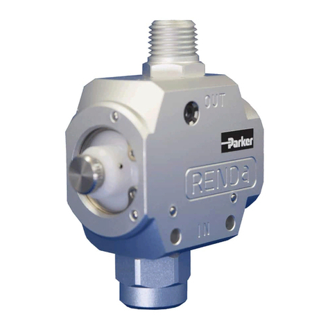
Parker
Parker Sporlan SD-114 Installation and servicing instructions
Data Translation
Data Translation DT7837 user manual
EverFocus
EverFocus EMV400 HD Quick installation guide
NI
NI PXIe-1435 USER GUIDE AND SPECIFICATIONS
Squibb-Taylor
Squibb-Taylor AL1598P Installation, operation, maintenance, disassembly and assembly Instructions
