Page 6
the suction line. The high pressure port is open and
liquid line pressure is applied to the underside of the
thermostatic expansion valve diaphragm. This high-
side pressure instantly overcomes the bulb pressure
and supplements of the valve spring, immediately
closing the port of the expansion valve.
Upon re-energizing the solenoid coil, the low pres-
sure port of the 180 opens and allows instantaneous
relief of pressure under the thermostatic expansion
valve diaphragm and normal operation of the ther-
mostatic expansion valve.
RECOMMENDATIONS
All refrigeration and air conditioning systems
should be protected from moisture and other sys-
tem contaminants by the Sporlan Catch-All®Filter-
Drier. When using the Type 180 Solenoid Pilot
Control, the expansion valve is used to shut off the
liquid line in place of a standard liquid line solenoid
valve. Therefore, it is essential that the system be
free of these contaminants which might prevent the
thermostatic expansion valve from seating tight.
The Type 180 may be installed either upright or on
its side. However, it should not be mounted with
the coil housing below the valve body.
INSTALLATION
In addition to first cost, flexibility of the Type
180 offers an installation savings. Standard 1/4”
soft copper tubing is the only tubing required for
the three valve connections. A C-032-F Catch-All
Filter-Drier is furnished with each Type 180, since
protection of the valve ports from system contami-
nants is important for proper operation.
ELECTRICAL
For normal summer operation of air conditioning
systems, the Type 180 Solenoid Pilot Control may
be energized through any actuating device such as
a thermostat, a micro-switch, or a manual switch.
The compressor can be operated separately through
the magnetic starter, wired with a low pressure cut-
out switch for pump down control.
If it is necessary to shut down a system for a long
period, the main liquid line or receiver valve should
be closed before de-energizing the entire system at
the main electrical service switch. This will protect
against compressor floodback if any unusual pres-
sure conditions occur during shutdown.
SERVICING SUGGESTIONS
The Type 180 Solenoid Pilot Control cannot be
taken apart in the field. To properly analyze sus-
pected trouble on an installation, it is advisable to
install a pressure gauge by means of a “T” fitting
in the external equalizer connection to the thermo-
static expansion valve.
By successively opening and closing the circuit to
the Pilot Control only, with the refrigeration sys-
tem and circulating fans or pumps in operation,
variations approximating condensing pressure and
suction pressure should be observed on this gauge.
A. If pressure does not build up rapidly to condens-
ing pressure when the Pilot Control is de-ener-
gized, proceed as follows:
1. Make certain that the electrical circuit has been
broken to the Pilot Control. Since the actuat-
ing device is generally at a remote point, we
suggest that a means for temporarily interrupt-
ing the current be made near the valve installa-
tion to facilitate servicing the equipment.
2. Check to see that no restriction exists and pres-
sure is ahead of both the Solenoid Pilot Control
and the C-032-F Catch-All Filter-Drier.
Type 180 Standard Coil Ratings
Connections - 1/4 SAE Flare Volts/Cycles Watts
MOPD
psi
300 AC 24/50-60
120/50-60
208-240/50-60
120-208-240/50-60
15225 DC
Maximum Rated Pressure - psi 500
Specifications - MKC-2 Coil
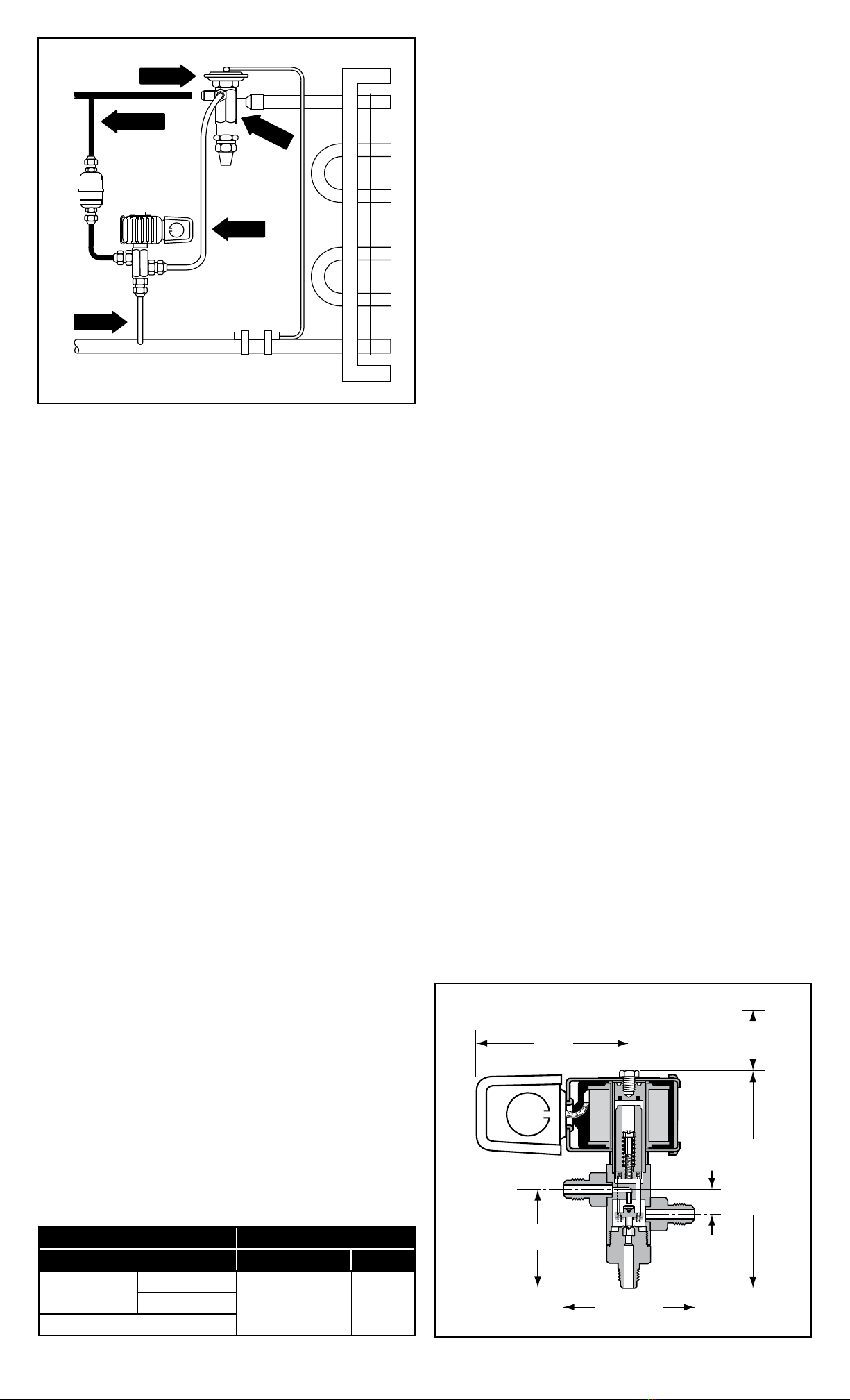
Suction
3.17”
81 mm
High
Pressure Inlet
Common
2.00”
51 mm
2.66”/ 68 mm
0.44”
11 mm
4.50”/ 114 mm
1.75”/ 44 mm
Coil Removal
Dimensions - Inches (mm)
Bulb Pressure
Spring
Pressure
Evaporator
Pressure
Head
Pressure
Evaporator
Pressure
120 LBS.
49 LBS.
40 LBS.
40 LBS.
9 LBS.
Figure 4