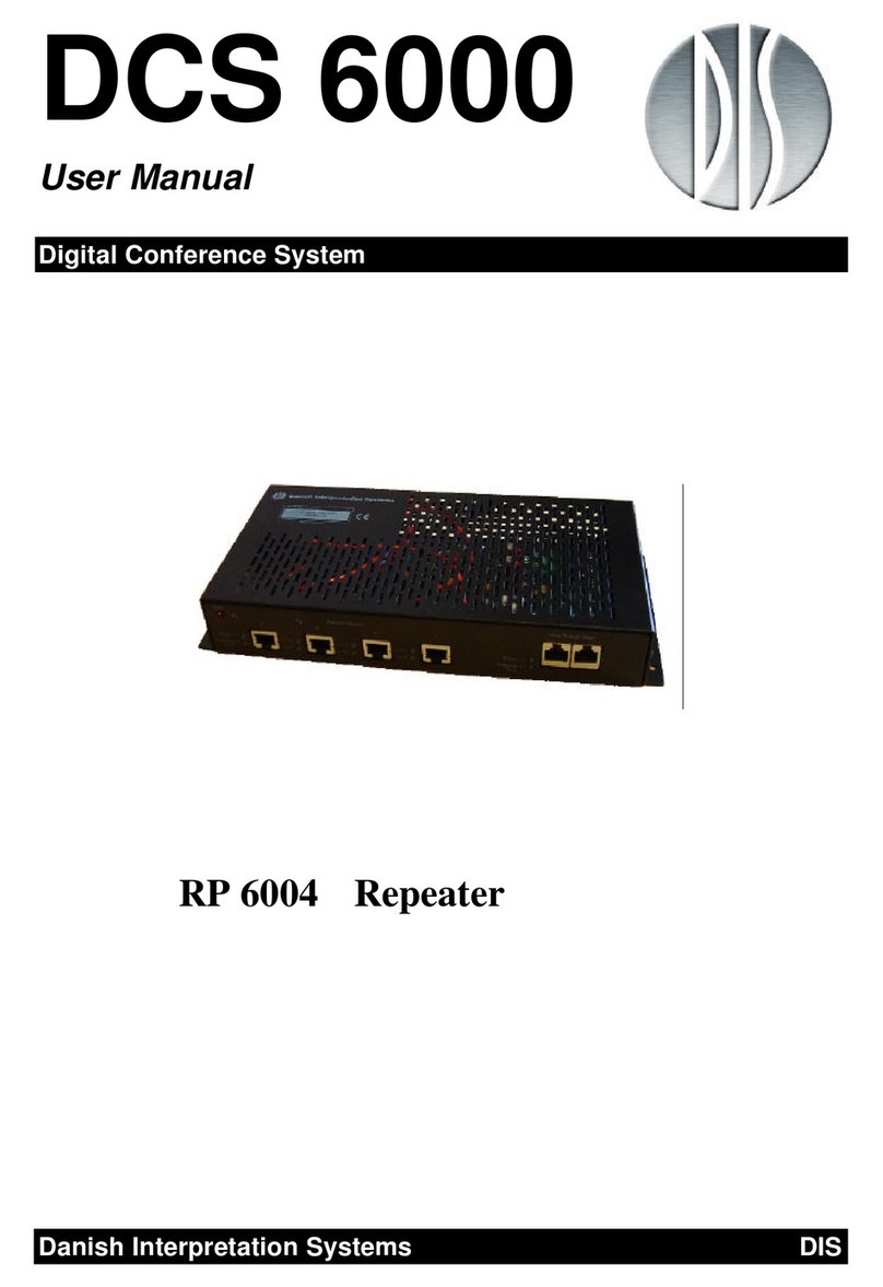
Delta Controls DZNR-768 User manual

DZNR-768
Installation Guide
Edition 1.5

Page 2 of 28 DZNR-768 Revision 1.2 Installation Guide
Document Edition 1.5
Copyright
Copyright © Delta Controls Inc. All rights reserved.
No part of this document may be reproduced, transmitted, transcribed, stored in a retrieval
system or translated into any language (natural or computer), in any form or by any means,
without the prior written permission of Delta Controls Inc.
Limited permission is granted to reproduce documents released in Adobe Portable Document
Format (PDF) electronic format in paper format. Documents released in PDF electronic format
may be printed by end users for their own use using a printer such as an inkjet or laser device.
Authorized distributors of Delta Controls Inc. products (Delta Partners) may print PDF
documents for their own internal use or for use by their customers. Authorized Delta Partners
may produce copies of released PDF documents with the prior written permission of Delta
Controls Inc.
Information in this document is subject to change without notice and does not represent a
commitment to past versions of this document on the part of Delta Controls Inc. Delta Controls
Inc. may make improvements and/or changes to this document /the associated software/or
associated hardware at any time.
BACspec, BACstat, the Delta logo, ORCAview, ORCAweb, Earthright, enteliWEB, enteliBUS,
enteliMESH, enteliTOUCH, enteliZONE, enteliSTAT, enteliVIZ and Virtual Stat are registered
trademarks of Delta Controls Inc.
All other trademarks are the property of their respective owners.
Document Edition: 1.5
Updated on: December 23, 2016

DZNR-768 Revision 1.2 Installation Guide Page 3 of 28
Document Edition 1.5
Contents
Contents .....................................................................................................................................3
Product description....................................................................................................................5
Package contents ....................................................................................................................6
Related documents .................................................................................................................6
Cautions or warnings ..............................................................................................................6
Mounting ....................................................................................................................................7
Board layout...............................................................................................................................8
Repeater configuration ..............................................................................................................9
Baud rate jumper ....................................................................................................................9
Fixed baud rate selection.....................................................................................................9
Auto baud rate selection......................................................................................................9
Data wires termination jumper .............................................................................................10
MS/TP 2 WIRE termination ................................................................................................10
MS/TP RJ-45 termination ..................................................................................................10
Wiring general..........................................................................................................................11
Power and grounding ...............................................................................................................12
Network layout.........................................................................................................................14
Example network layout diagram..........................................................................................15
MS/TP 2 WIRE segment.........................................................................................................16
Shield continuity and termination ......................................................................................16
MS/TP RJ-45 segment...........................................................................................................17
Segment length calculation ...............................................................................................17

Contents
Page 4 of 28 DZNR-768 Revision 1.2 Installation Guide
Document Edition 1.5
DZNR label ...............................................................................................................................18
Status indicators ......................................................................................................................19
Diagnostics and troubleshooting..............................................................................................20
DZNR power-up sequence.....................................................................................................20
Recommended diagnostic procedure ....................................................................................20
Advanced diagnostics............................................................................................................22
Segment lockout................................................................................................................22
Troubleshoot complex communications problems ............................................................22
Product specifications ..............................................................................................................24
Document revision history .......................................................................................................27

DZNR-768 Revision 1.2 Installation Guide Page 5 of 28
Document Edition 1.5
Product description
The DZNR-768 (Delta Zone Network Repeater-768) is a four-port repeater that extends the
number of devices on a BACnet RS-485 MS/TP network and improves the signal quality on the
network.
The DZNR-768 divides a network into four segments allowing a maximum of 64 devices per
segment and a total of 99 devices per network.
Each segment can accommodate either the quick-connect MS/TP RJ-45 cabling used on the
DZNT-VAV product or standard MS/TP 2 WIRE cabling.
The DZNR-768 continuously monitors network traffic and uses its built-in diagnostics and
LEDs to provide a quick view of the status of every connected device. 17 general status LEDs
and 101 individual device LEDs allow you to diagnosis and troubleshoot network problems
visually.
This document describes the Revision 1.2 DZNR-768 which was released in 2013. Throughout
this document DZNR means DZNR-768.
DZNR-768 Rev 1.2

Product description
Page 6 of 28 DZNR-768 Revision 1.2 Installation Guide
Document Edition 1.5
Package contents
•Product: DZNR-768, Rev. 1.2
Related documents
•Delta Controls Wiring and Installation Guidelines
Cautions or warnings
This controller is an Electro-statically sensitive device. Proper ESD protection such as a
ground strap is required when installing this product so that damage to the product
does not occur.
Equipment damage or loss of data may occur if these procedures are not followed as
specified.
Installations requiring CE conformance:
All wiring for CE rated products must use an extra low voltage (SELV) or protective
extra low voltage (PELV) transformer. Use safety-isolating transformers, (Class II
transformer) per EN61558. The transformer must be rated for 100% duty cycle.

DZNR-768 Revision 1.2 Installation Guide Page 7 of 28
Document Edition 1.5
Mounting
The DZNR-768 includes a plastic enclosure that can be mounted quickly with two screws or
snapped into 35mm DIN rail. Mount the DZNR in an appropriate location near the system
controller in an enclosure that meets code requirements.
D
CE
A
B
Dimension
mm
in.
A 107 4 1/4
B
49
1 15/16
C
192
7 9/16
D 204 8 1/16
E
218
8 9/16
PCB width
100
3 15/16
PCB length 184 7 1/4

Board layout
Page 8 of 28 DZNR-768 Revision 1.2 Installation Guide
Document Edition 1.5
Board layout
Do not wire both MS/TP 2 WIRE and MS/TP RJ-45 wiring styles on the same segment.
Only the MS/TP 2 WIRE or MS/TP RJ-45 may be used on one segment.

DZNR-768 Revision 1.2 Installation Guide Page 9 of 28
Document Edition 1.5
Repeater configuration
The DNZR-768 requires the following five jumper settings.
•Baud rate
•Data wires termination for segment 1
•Data wires termination for segment 2
•Data wires termination for segment 3
•Data wires termination for segment 4
Baud rate jumper
The DZNR baud rate is set by positioning a jumper across the appropriate speed pins. Fixed
speeds range from 9600 to 76800 bps, or the Auto Baud setting may be used.
The same baud rate must be used for all network segments.
If multiple jumpers are in place or no jumper is in place, the DZNR sets its baud rate to 76800
bps.
Fixed baud rate selection
Place one jumper for the chosen baud rate from 9600 to 76800 bps. The DZNR operates only at
that baud rate. The LED adjacent to the selected speed is illuminated
AUTO
76800
38400
19200
9600
Auto baud rate selection
Place one jumper on the AUTO position. The DZNR attempts to set its baud rate to match the
baud rate of the controller on segment 1. If no device is connected to Segment 1, then the
DZNR sets its baud rate to 76800. The LED adjacent to the detected speed is illuminated.

Repeater configuration
Page 10 of 28 DZNR-768 Revision 1.2 Installation Guide
Document Edition 1.5
Data wires termination jumper
The segment data wires are terminated differently for MS/TP 2 WIRE and for MS/TP RJ-45.
See the corresponding section below for a description of the proper termination.
Proper termination of the network data wires ensures network stability and helps to prevent
damage to controllers during high electrical activity.
MS/TP 2 WIRE termination
The data wires at both ends of an MS/TP 2 WIRE segment must be terminated to ensure
reliable operation. The DZNR provides a built-in jumper-selectable termination for the data
wires of each segment.
For MS/TP 2 WIRE, set the jumper for the segment to the TERM position. Terminate the data
wires at the last node on the segment with a TRM-768. The following diagram shows the
proper termination for both the data wires and the shield.
RS-485 port
+
-MS/TP 2 WIRE port
+
-
Last node
on segment
Keep stub cable length
as short as possible
GND
TRM-768
Shield
+DZNR with TERM
jumper set to enable
built-in segment
termination
Shield is not grounded
at this end of segment
MS/TP RJ-45 termination
For MS/TP RJ-45, remove the jumper for the segment or set it to the non- TERM position.
Devices that use MS/TP RJ-45 networking include built-in distributed termination components.

DZNR-768 Revision 1.2 Installation Guide Page 11 of 28
Document Edition 1.5
Wiring general
All wiring must conform to NEC, local codes and regulations. Earth ground isolating step-down
Class 2 transformers are required. Do not use autotransformers. Determine the supply
transformer rating by total VA of product.
Risk of Electric Shock or Fire
Use Class 2 Circuit connections only for all terminals
Use only 12-22 AWG copper conductors, rated 149
°
F (65
°
C).

Power and grounding
Page 12 of 28 DZNR-768 Revision 1.2 Installation Guide
Document Edition 1.5
Power and grounding
The DZNR-768 uses a 24VAC Class 2 power supply. One transformer may be used to
independently supply power to the DZNR.
Alternatively, you can share one transformer to power the DZNR, additional controllers and/or
auxiliary field devices such as sensors and actuators. When this approach is taken, the
following conditions must be met:
•All devices MUST be half-wave rectified. Mixing power between half-wave and full wave
rectified devices will damage both the transformer and connected equipment.
•The transformer is properly sized, including line losses for the total VA requirements.
•Polarity is observed between controllers with respect to 24~ and GND.
•Each controller is grounded as shown in the diagram below. This is important to protect
equipment and ensure a common ground reference for RS-485 communications.
•The transformer secondary is fused for its maximum rated load (4A max for Class 2
circuits).
•All devices sharing power must be on the same network segment.
24VAC
Ground the ground lug If no ground lug is present, ground
any one terminal labeled GND
24~ GND GND IP2
24~ GND
X1 X2

DZNR-768 Revision 1.2 Installation Guide Page 13 of 28
Document Edition 1.5
Make sure to ground the DZNR using the ground lug that is available on
the DZNR. The DZNR
uses the ground lug to establish a common reference
for communications. If the DZNR is not grounded then communication
problems may occur.
Select an external power supply that is certified for safety for the correct
destination country and that has an output rating, which is considered an
NEC Class 2 or Limited Power Source with the rating not to exceed 30 V
rms, 42.4 V peak, 100 VA.
Be sure that the transformer polarity is consistent across all controllers
sharing a common transformer.
Refer to the Delta Controls Wiring and Installation Guidelines document
for additional information and wiring options.

Network layout
Page 14 of 28 DZNR-768 Revision 1.2 Installation Guide
Document Edition 1.5
Network layout
The DZNR accommodates both twisted pair and Cat5 wiring methods for Rs-485 MS/TP
networks. Each of the DZNR’s four ports divides the network into individual segments. On each
port you can select either the twisted pair or Cat5 media. Use only one or the other wiring
methods on each port. Do not connect both the twisted pair and Cat5 types to the same port.
Hardware revisions prior to 1.2 support Cat5 only on ports 3 and 4.
The Delta MS/TP Cat5 or higher (Cat5e, Cat6, etc) cabling technique allows quick, error-free
connections across the controllers on the MS/TP segment. Applying Delta’s ADP45-MSTP
family of Cat5 accessories further expands wiring options.
The network system controller is placed on Port 1 and is assigned a network MAC address of 0.
Ports 2, 3 and 4 are used to interconnect the remaining controllers.
No more than 64 controllers can be connected to any one segment and no more than 99 total
controllers are recommended per DZNR.
Wiring and data wires termination must conform to the recommendations in Delta Controls
Installation and Wiring Guidelines for wire length, shielding and grounding for each wiring
segment.

DZNR-768 Revision 1.2 Installation Guide Page 15 of 28
Document Edition 1.5
Example network layout diagram
This diagram shows both a MS/TP 2- WIRE segment and a MS/TP RJ-45 segment.
Twisted Pair Segment
DAC DAC
ADP45-MSTP-EOL
End of Line
Loopback
DSC
NET2
DZNR
Twisted Pair Segment
To DZNR port 1
CAT5 Segment
ADP45-MSTP-EOL
End of Line
Loopback
CAT5 branch using
ADP45-MSTP-Y
adapter
DAC
Terminator
TRM-768
Terminator
TRM-768
Add one two-wire RS-485 device
using ADP45-MSTP-TB-Y adapter DAC
Short two-wire RS-485 wire
included with adapter
1

Network layout
Page 16 of 28 DZNR-768 Revision 1.2 Installation Guide
Document Edition 1.5
MS/TP 2 WIRE segment
When using a MS/TP 2 WIRE port for twisted pair wiring, follow the wiring conventions
described in the Delta Controls Wiring and installation Guidelines document. The guidelines
include the following cable specifications:
•22-24 AWG twisted pair
•100-120 ohms impedance
•17 pF/ft or lower capacitance
•Braided or aluminum foil shield
Wire the controllers on the segment in a daisy-chain fashion. Attempting to connect them
using a starred or bus configuration will cause problems on the segment. The maximum
length for each MS/TP 2 wire segment is 4000 ft (1220 m).
Shield continuity and termination
For MS/TP 2 WIRE segments, the shield must be continuous from node to node and be
terminated as shown in the diagram found here: Data wires termination jumpers
Do not connect the shield to the ground lug.

DZNR-768 Revision 1.2 Installation Guide Page 17 of 28
Document Edition 1.5
MS/TP RJ-45 segment
Each of the four ports of the DZNR-768 has an RJ-45 jack that allows use of straight-through
unshielded twisted pair (UTP) Cat5 or higher (Cat5e, Cat6, etc.) cables.
For this type of wiring configuration, Delta provides the ADP45-MSTP accessory adapters that
allow you to split the segment, provide end-of-line loopback, convert between types of wiring
media and temporarily bypass missing or defective controllers.
Segment length calculation
The total length of a MS/TP RJ-45 network segment must not exceed 2000 ft (610 m). Segment
length is determined by the sum of all cable lengths, including runs between ADP45-MSTP
adapters, controllers and sensors. The following diagram provides an example of how MS/TP
RJ-45 segment length must be calculated.
ADP45-MSTP-EOL
End of Line
Loopback
250 ft
76.2 m 50 ft
15.2 m 100 ft
30.5 m 300 ft
91.4 m
700 ft
213.3 m
25 ft
7.6 m
RJ-45 Segment Length Calculation
(2 x 50) + (8 x 25) + (4 x 100) + 250 + 300 + 700 = 1950
1950 ft < 2000 ft therefore segment length is acceptable
DZNR
ADP45-MSTP-EOL
End of Line
Loopback
CAT5 branch using
ADP45-MSTP-Y adapter
100 ft
30.5 m
100 ft
30.5 m 100 ft
30.5 m
50 ft
15.2 m
25 ft
7.6 m 25 ft
7.6 m 25 ft
7.6 m
25 ft
7.6 m 25 ft
7.6 m 25 ft
7.6 m
25 ft
7.6 m

DZNR label
Page 18 of 28 DZNR-768 Revision 1.2 Installation Guide
Document Edition 1.5
DZNR label
You can use the label on the cover of the DZNR to identify the status indicator LED that is
assigned to each of the network devices. The label also includes quick reference information
for common diagnostic problems.
Each white box on the label corresponds to a status indicator LED mounted on the DZNR circuit
board. The LED indicates the status of the corresponding controller. Once the network
installation is finalized, shade the white boxes on the label to mark the location of each
controller. If the shading is done in pencil, future changes can be made by erasing the old
marks and filling in new ones.
The LEDs numbered from 0 through 99 correspond to controllers with that MAC address on
the network. Devices with MAC address above 99, including the CON-768 service tool which
assumes a default address of 127, are collectively monitored on the LED labeled as 100-127.
To determine controller status, compare the condition of the LEDs against the network layout
on the label. See Diagnostics and troubleshooting for a description of the illumination patterns
for these LEDs.
5V10V4-20mA 10k
4-20mA 10k 5V10V
4-20mA 10k 5V10V
4-20mA 10k 5V10V
4-20mA 10k 5V10V
4-20mA 10k 5V10V
INPUT TYPE
SELECTORS
EXTERNAL
INTERNAL
DZNR-768
BACnet MS/TP REPEATER
Made in Canada
24~
GND
PWR
Class 2 Device - All terminals Class 2 / SELV
Use 12 – 22AWG copper conductor only (65°C)
Ambient Rating: 32° to 132°F (0° to 55°C)
INSTALL GUIDE
https://support.deltacontrols.com
INPUT POWER:
24VAC 50/60Hz
CLASS 2, 7VA
OPEN ENERGY
MANAGEMENT EQUIPMENT
74FK
DIAGNOSTICS – UPPER STATUS LEDs
LED ON – CONTROLLER ON LINE
LED FLASHING FAST – DUPLICATE ADDRESS
LED FLASHING SLOW – CONTROLLER STOPPED COMMUNICATION
GND
DIAGNOSTICS – ERROR LEDs
GREEN = HEALTHY NETWORK
YELLOW = NETWORK MARGINAL – CHECK INSTALL GUIDE FOR TIPS
RED = MAJOR NETWORK PROBLEM – SEGMENT LOCKED OUT
-
+
MS/TP
2 WIRE
1 2
MS/TP
RJ-45
<-OR->
SEG 1 SYSTEM CONTROLLER
-
+
MS/TP
2 WIRE
12
MS/TP
RJ-45
<-OR->
SEG 2 ZONE CONTROLLERS
-
+
MS/TP
2 WIRE
1 2
MS/TP
RJ-45
<-OR->
SEG 3 ZONE CONTROLLERS
-
+
MS/TP
2 WIRE
12
MS/TP
RJ-45
<-OR->
SEG 4 ZONE CONTROLLERS
11611
621 25
26 4136
31 46 50
51 6661
56 71 75
76 9186
81 96 99 100-127
0
SYSTEM
CONTROLLER
ERRERR
ERRERR

DZNR-768 Revision 1.2 Installation Guide Page 19 of 28
Document Edition 1.5
Status indicators
A great deal of information about the operation of each connected controller and the overall
integrity of each segment is available from careful observation of the LED indicators
The following table summarizes the purpose and the types of status information represented
by each LED or LED group.
LED Indicates Description
POWER DZNR is powered. Amber LED is ON steady for normal operation
and OFF when power is disconnected or a fuse
is blown.
Tx
(MS/TP
segments 1-4)
DZNR sending
information on associated
RS-485 segment.
Green LED blinks quickly in a regular pattern.
Rx
(MS/TP
segments 1-4)
DZNR receiving
information on associated
RS-485 segment.
Red LED blinks quickly in a regular pattern.
ERR
(MS/TP
segments 1-4)
Status of associated RS-
485 segment.
This is a tri-color LED. If color is a steady
green, then the network segment is OK. If color
is amber or red, network errors are present.
BAUD RATE Current operating baud
rate
Only one LED is lit, indicating operational baud
rate.
DEVICE ID
(0 to 99)
Each individual device
online.
LEDs provide individual online indication for
devices in the range 0-99.
DEVICE ID
(100-127)
One or more devices are
online.
LED provide online indication for devices in the
range 100-127, including the CON-768 service
tool, which assumes a default address of 127.
For Device IDs greater than 99, visual indication is limited to whether the
device is present (LED on) or not (LED off). It does not attempt to identify
any of the same diagnostic conditions as for devices 0 to 99.

Diagnostics and troubleshooting
Page 20 of 28 DZNR-768 Revision 1.2 Installation Guide
Document Edition 1.5
Diagnostics and troubleshooting
Troubleshooting a large network is easier when the controllers are distributed over multiple
segments. In this way, a failure is restricted to a particular segment rather than appearing
across the entire network. The DZNR quickly shows the status of every device on every
segment. By observing deviations from a normal LED pattern, one can determine if the
network is performing optimally or whether a possible device or wiring problem may exist.
DZNR power-up sequence
After the DZNR first powers up, it goes through a brief self-initialization period. All the LED
indicators turn on for 5 seconds. During this period, the DZNR examines every device that is
properly communicating on the network and retains those addresses until it loses power or is
reset. If a device fails to communicate during the initialization period, it will not be recognized
by the DZNR and its LED remains off. However, any missing device can be checked against the
label as to ascertain whether it is present or missing.
Recommended diagnostic procedure
Most network faults are steady state. With the DZNR, you can quickly determine if a specific
problem is unique to a particular device and isolated to one segment. Steady state problems
include: failure of a device, duplicate address of two or more devices, or a break in the wiring.
Using a consistent and methodical approach, the following diagnostic procedure is
recommended:
1. Note the condition of the device status LEDs and compare them to the known devices
shown on the DZNR label
2. Analyze the status of each segment Err LED
3. Check the state of the TX and RX LEDs on each segment
The following table describes the most common network problems and their associated LED
indications. Note the condition of the normal network. The goal of any troubleshooting exercise
is to restore the network is to its normal level of functionality.
Table of contents
