Entel RP510 User manual

User Guide – RP500 Series
Professional compact repeater base station
v07/08
Common nformation
RP510/520/580/580-U

Table of Contents
Common Information Page
Certification 2
Radio care / First Time Use 3
Packing List / Optional Accessories 4
Preparing the Base Station for use 5
RP500
Feature List 6
Controls & ndicators 7 & 8
Feature Operation 9
Troubleshooting Guide 10
ntroduction
This guide covers the ‘basics’ of your base station operation.To meet your exact re-
quirements the radio may have been customised by your Entel authorised dealer.
These features will be explained in a separate guide issued by the dealer.
1
Common

Common
Certification
Declaration of Conformity
The RP500 base station displays "CE" on the rear label, indicating its compliance with
the essential requirements of the EEC directive for Electromagnetic Compatibility.
CE Compliance Statement
We Entel UK Limited
OF:
4 Elstree Gate,
Elstree Way
Borehamwood
Hertfordshire
WD6 1JD
United Kingdom
Declare under our sole responsibility that the product:-
RP500 base station transceiver
Serial Number________________________________
To which this declaration relates, is in accordance with directive 99/5/EC
and conforms to the following standard or other nominative documents:-
EN 300 086 (March 2001), EN 301 489-1 V1.3.1:2003, EN 60065:2002
Following provisions of the R&TTE directive.
M Austin
Quality Manager
2

Radio care
Advice
•Do not use options or accessories not
specified by Entel
•Ensure that the radio is used within the
parameters for which it was designed
•Keep dry, do not use in high humidity areas
Warning
•Disconnect from the mains before fitting any
accessories or removing any cover
Do not install the transceiver in the following
locations:
•n explosive atmospheres (flammable gas, dust
including metallic & grain powders etc)
•Near explosives or blasting sites
Caution
•Do not disassemble or modify the transceiver
for any reason
•Do not transmit without an antenna fitted, be
aware the base station will automatically
transmit when talk-through is enabled
•Do not transmit while touching the antenna
terminal or any exposed metallic parts of the
aerial as this may result in a burn
•Do not obstruct the fan/vents
•Always replace fuses with the same rating.
Never fit a fuse of a higher rating. Replace
the fuse only after investigating and correcting
the cause of the blown fuse
End of Life Disposal
•When your Entel transceiver reaches the end
of its useful life, please ensure that the unit is
disposed of in an environmentally friendly way.
For country specific information please see
www.entel.co.uk/recycling/index.htm.
3
Common

Common
Power Options
CNB550 nternal rechargeable lithium ion battery
RP5DCL External DC cable for connection to external battery
Hardware Options
RPBRAK Wall mount installation bracket
MPX70 nternally mounted UHF duplexer for single antenna operation
MPX26 nternally mountedVHF High Band duplexer for single antenna operation
DPF4/6 Externally mountedVHF Mid Band duplexer for single antenna operation
RPSCR Voice scrambler
Audio Accessory Options
CMP550 Heavy duty speaker microphone
DMP550 Desk microphone
DMP550BT Desk microphone with bluetooth
4
Optional Accessories
•RP500 Base Station Transceiver
•Mains EC power lead
•UG500 User guide
Packing list

5
Preparing the base station for use
Before use he k the following:
The external antenna connection is correctly fitted to the base station before it is switched on.
Dependent upon configuration either one or both ‘N Type’ sockets may be used. Check with
your dealer.
The antenna plug must be screwed fully on to the socket. Failure to attach the antenna correctly
can lead to poor performance and damage the unit.
Turn the base station on/off
When powered from the mains, use the rear mounted isolator switch to power the base.To turn
the base on/off turn the front mounted on/off volume control clockwise.
Re eiving alls on the base station
Calls can be monitored on the base station utilising the internal loudspeaker. Use the on/off vol-
ume control to set a comfortable listening volume.
Atta hing / Removing an optional lo al ontrol mi rophone
Calls can be made from the base station using one of the Entel approved microphone options.To
insert the optional local control microphone, ensure that the plug with the locking nib is upper-
most and push the plug in to the socket until it clicks in to place.To remove the plug, push down
the nib on the plug and pull out.
Talk Through enable/disable
Talk Through facility can be enabled or disabled from the front of the base station.To enable
press the talk through button and the LED will illuminate to show the feature is active.To disable
press the talk through button again (the LED will extinguish)
Common
Nib
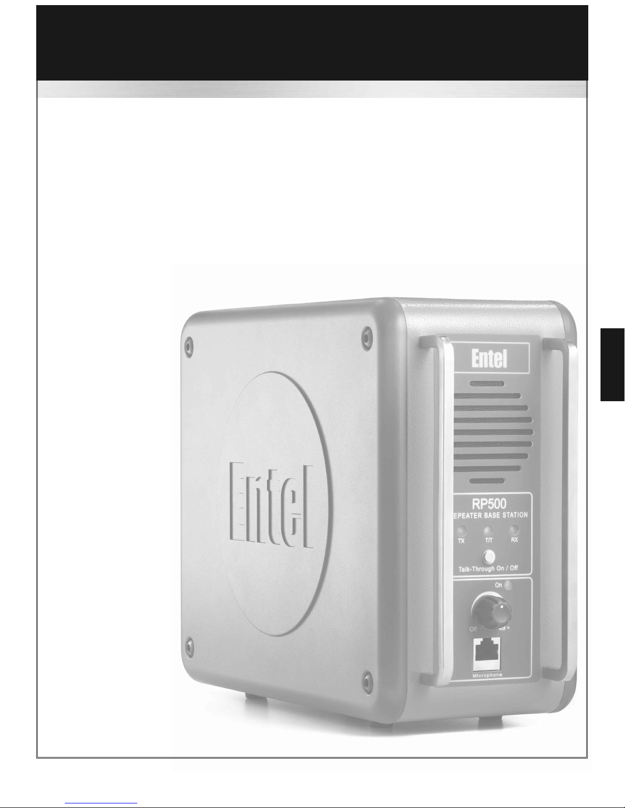
RP500
Standard Features:
•Single channel
•Transmit power output 5 WattsVHF, 4 Watts UHF, 1 Watt low power
•100% duty cycle
•CTCSS & DCS (Analogue & Digital squelch) with squelch tail elimination
•Second receiver (for country specific licensing requirements)
•Dealer adjustable transmit tail with pip tones
•Exceptionally loud and clear audio
•Talk through on / off button
•Local control with optional microphone
•Mains failure alert indicates when optional back-up battery is in use
Dealer fit options:
•Voice scrambler (when local control is required on an encrypted system)
•nternal Duplexer for single antenna operation (external on RP510)
•nternal 3.6AH Lithium on battery
RP500
6

Controls & ndicators
7
5nternal
loudpeaker
6Receive signal
LED
7Power LED
4TalkThrough
on / off LED
3Transmit LED
2Talk Through
on / off switch
1On / Off
Volume control 8Microphone /
control panel
socket
1On / Off Volume control - Rotate clockwise to turn on and increase volume, anticlockwise to
decrease and turn off.
2Talk Through switch - Press to select / deselect talk through
3Transmit LED - will illuminate red when the base is transmitting
4Talk Through LED - will illuminate white when talk through is enabled
5nternal loudspeaker - to monitor transmissions through the base station
6Receive signal LED - will illuminate green when a transmission is being received
7Power LED - will illuminate blue when the base is switched on
8Microphone socket - nsert optional microphone to enable local control use
RP500
8
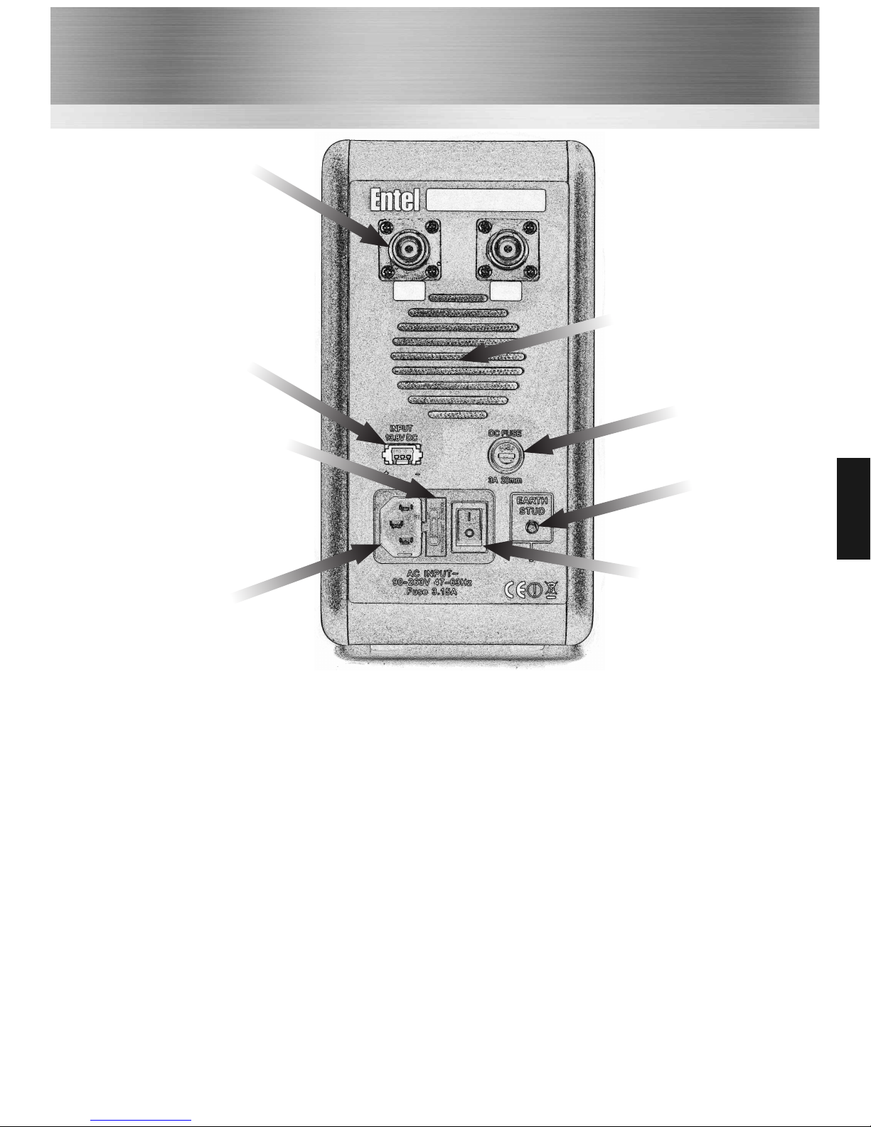
Controls and ndicators Cont
1Mains input
2Mains fuse
3External
13.8VDC input
4Antenna
sockets
8On / Off switch
7Earth stud
6External
13.8VDC fuse
1Mains input - 110-240 EC mains power input socket
2Mains fuse - 3.15A 20mm mains protection fuse
3External 13.8VDC input - to provide an external source to power the base station
4Antenna sockets - One or both sockets may be used dependant upon configuration
5Extractor fan - Dealer configurable, continuous - temperature - or transmit operation
6External 13.8VDC fuse - External power input 3A DC protection fuse
7Earth stud
8On / Off switch - AC mains power switch
RP500
5Fan

12V Operation
There are 2 methods to operate your base station from 12VDC.
External back-up battery
Using the optional RP5DCL lead, an external 12V lead acid back-up battery can be connected. The
base station will float charge the battery whilst powered from a mains source.The maximum
charge current the base will deliver is 3A.
nternal Lithium on battery option
A dealer fit 3.6AH lithium on rechargeable battery can be fitted.Whilst powered from the mains,
the base station will charge the internal battery.
Transmit Tail & Pip Tones
When used in talk through, the base station has an adjustable transmit tail length, dealer adjustable
between 3 - 46 seconds.The transmit tail will keep the base station on transmit for the pre-set
time after a radio user has ended their transmission.To indicate the transmit tail to all users on the
radio system the base will generate pip tones for the duration of the transmit tail. f you transmit
during the transmit tail, the pip tones will stop and your transmission will be heard.
Cooling Fan
The rear mounted cooling fan has 3 dealer configurable operating modes.
1 Fan operates continuous while base is switched on
2 Fan operates only when base is transmitting
3 Fan disabled.
Dual Receiver
Your base station is fitted with two receivers.Where country licensing dictates, the second receiver
will be used to monitor for transmissions on the base stations transmit channel. f a signal is
detected on this channel the base will be prevented from transmitting.The second receiver cannot
be used to monitor transmissions, it is used only to lock out the transmitter function.
Mains Failure / 12V Operation Warning
f an optional mains failure back-up battery is fitted or if base is only powered from 12V battery
then a low level pip tone will sound on all transmissions to alert users that the base station is not
mains powered. (This feature is dealer programmable and can be disabled).
Talk Through & Local Control
The base station has a front mounted talk through on/off button.When talk through is on, this will
allow users to communicate using the base as a relay.Turning talk through off will prevent users
talking to each other and will only allow communication to the base. Using an optional microphone
allows the base to be used as an additional radio.
Feature Operation
RP500
9

PROBLEM PROBABLE CAUSE SOLUTION
Radios cannot talk to each
other through the base
station
Talk Through is switched off
Turn Talk Through on using
button on front panel of
base station.
am operating on batteries
and the range has suddenly
dropped
The base has automatically
switched to low power as
the batteries are getting low
Recharge battery / plug in to
mains supply if available
The base station does not
transmit and talk through is
switched on
The base has the dual
receiver active
Wait for a short period and
try again
The base station is pipping
when in use
This is a mains failure alert
to indicate that the base is
operating from a battery
The alert will end when the
base is powered from the
mains
Troubleshooting Guide
RP500
10
‘the
choice’
professional’s
Headquarters: United Kingdom www.entel. o.uk
Copyright Entel UK Ltd. 2007
< ntended Country Of Use>
BE
BG
CZ
DK
DE
EE
E
EL
ES
FR
T
CY
LV
LT
LU
HU
MT
NL
AT
PL
PT
RO
S
SK
F
SE
UK
This manual suits for next models
3
Table of contents
Other Entel Repeater manuals


