Delta Core GP8 Radio CPL User manual
*2702980_Ver.1*
Delta Dore hereby declares that the equipment complies with
the essential requirements and other relevant provisions of the
R&TTE Directive 1999/5/EC
The EC declaration of conformity for this equipment is available,
on request, from:
"Technical information" department
DELTA DORE - Bonnemain - 35270 Combourg (France)
Because of changes in standards and equipment, the characteristics
given in the text and the illustrations in this document are not binding
unless confirmed.
OK
OK
RF
RF
GP8 RADIO CPL
Amp.
15
50
45
35 30 25
20
60
63 10
75 7,5
90 5
CE
40
GP8 Radio CPL
Radio DRIVER
Energy manager

Contents
• Carefully read these instructions prior to installa-
tion.
• The unit must be installed in compliance with cur-
rent standards.
• Always switch off the mains before installing or
servicing the unit.
• Do not attempt to repair the unit yourself. After-sales
service is available.
• The diagrams provided are simplified for greater
clarity. Protective devices and other accessories
required by the standards are not illustrated.
Standard UTE NF C15-100 and good practice must
be complied with. Connected or nearby units must
not generate excessive interference (Directive
2004/108/EC).
• The GP8 RADIO PLC only works with a
RADIO DRIVER type of wireless programmer.
Warning
Description . . . . . . . . . . . . . . . . . . . . . . . . . . . 5
Positioning the GP8 RADIO PLC . . . . . . . . . . . . 5
Connecting the GP8 RADIO PLC . . . . . . . . . . . . 6
Commissioning the GP8 RADIO PLC . . . . . . . . 10
Mounting / Positioning the RADIO DRIVER . . . . 12
Quick association of the GP8 PLC
to the Radio Driver and PLC receivers . . . . . . . 14
Setting the time on the RADIO DRIVER . . . . . . 17
Configuration . . . . . . . . . . . . . . . . . . . . . . . . 18
Basic configurations (menu 1) . . . . . . . . . . . . 19
Programming type selection . . . . . . . . . . . . . . . . . 19
Programming increment selection . . . . . . . . . . . . 19
Pilot Wire type selection . . . . . . . . . . . . . . . . . . . . 20
DHW status in absence mode . . . . . . . . . . . . . . . 20
Advanced configurations (menu 2) . . . . . . . . . 21
Modification authorisation . . . . . . . . . . . . . . . . . . . 21
Temperature correction . . . . . . . . . . . . . . . . . . . . . 22
Pilot Wire order selection . . . . . . . . . . . . . . . . . . . 22
Tariff reduction selection . . . . . . . . . . . . . . . . . . . . 23
- 5 -
Contents Description
OK
OK
RF
RF
GP8 RADIO CPL
Amp.
15
50
45
35 30 25
20
60
63 10
75 7,5
90 5
CE
40
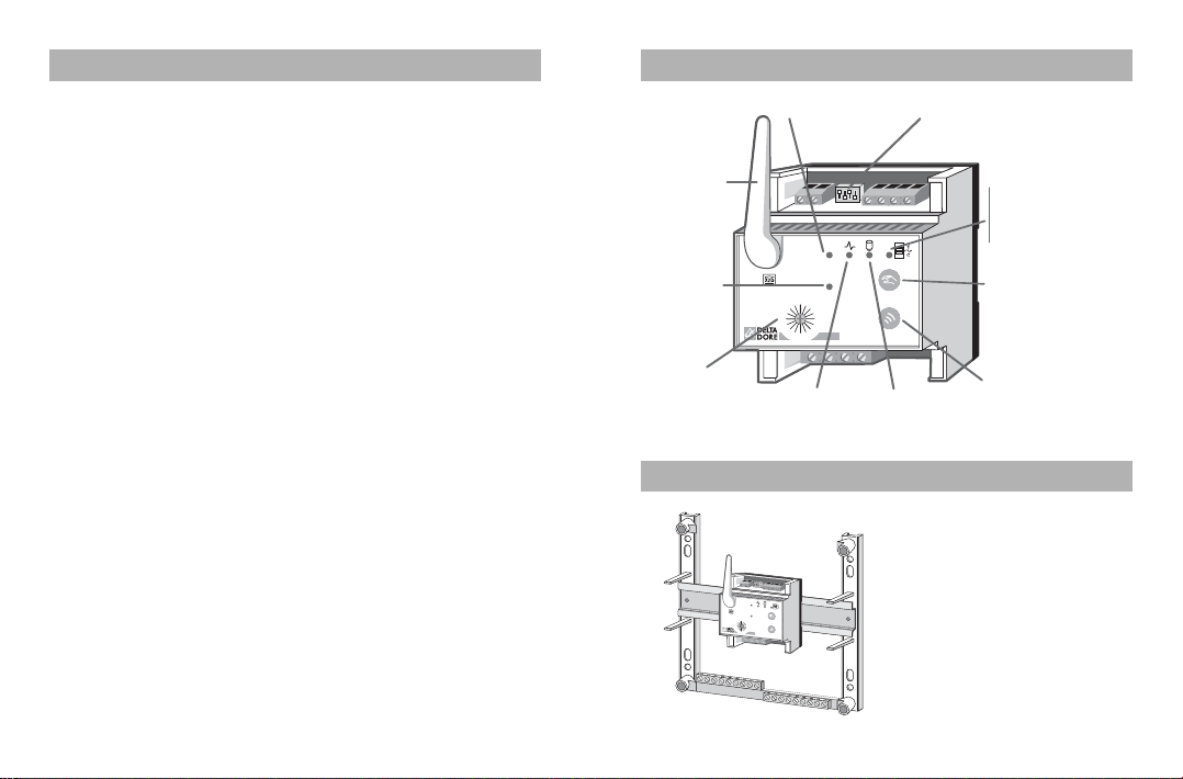
Antenna
Load
shedding LED
On = OK
Flashing = Fault
Off = Mechanical
meter
Wireless
association
button
PLC removal
button
PLC LED Load shedding type
DHW
LED
Meter
calibre
adjustment
Wireless
LED
Electronic
meter LED
Positioning the GP8 RADIO PLC
OK
OK
RF
RF
GP8 RADIO CPL
Amp.
15
50
45
353025
20
60
6310
757,5
905
CE
40
The modular unit is
mounted on a DIN rail•in
the electrical cabinet.
The antenna must be
installed vertically and
away from any metallic
mass.
Wireless/PLC association (menu R) . . . . . . . . . 25
Accessing the wireless association menu . . . . . . . 25
Home automation functions in the installation . . . 26
Consumption meter function . . . . . . . . . . . . . . . . . 27
Access to PLC configuration . . . . . . . . . . . . . . . . . 28
Associating a radio transmitter . . . . . . . . . . . . . . . 29
Associating PLC transmitters . . . . . . . . . . . . . . . . 33
Associating PLC receivers . . . . . . . . . . . . . . . . . . 34
Allocation of receivers on a three-phase system . 34
Re-associating PLC receivers . . . . . . . . . . . . . . . . 37
Associating a PLC receiver for DHW control . . . . 37
Configuration of the consumption
indication function (Menu 3) . . . . . . . . . . . . . 38
Consumption meter functions . . . . . . . . . . . . . . . . 38
Cost per kWh (inclusive of tax) . . . . . . . . . . . . . . . 39
Deleting wireless associations . . . . . . . . . . . . 41
Restore factory settings . . . . . . . . . . . . . . . . . 42
Wireless test . . . . . . . . . . . . . . . . . . . . . . . . . 43
Summary table of configurations . . . . . . . . . . . 44
Load shedding . . . . . . . . . . . . . . . . . . . . . . . 46
Technical characteristics . . . . . . . . . . . . . . . . . 47
Help . . . . . . . . . . . . . . . . . . . . . . . . . . . . . . . 49
- 6 - - 7 -
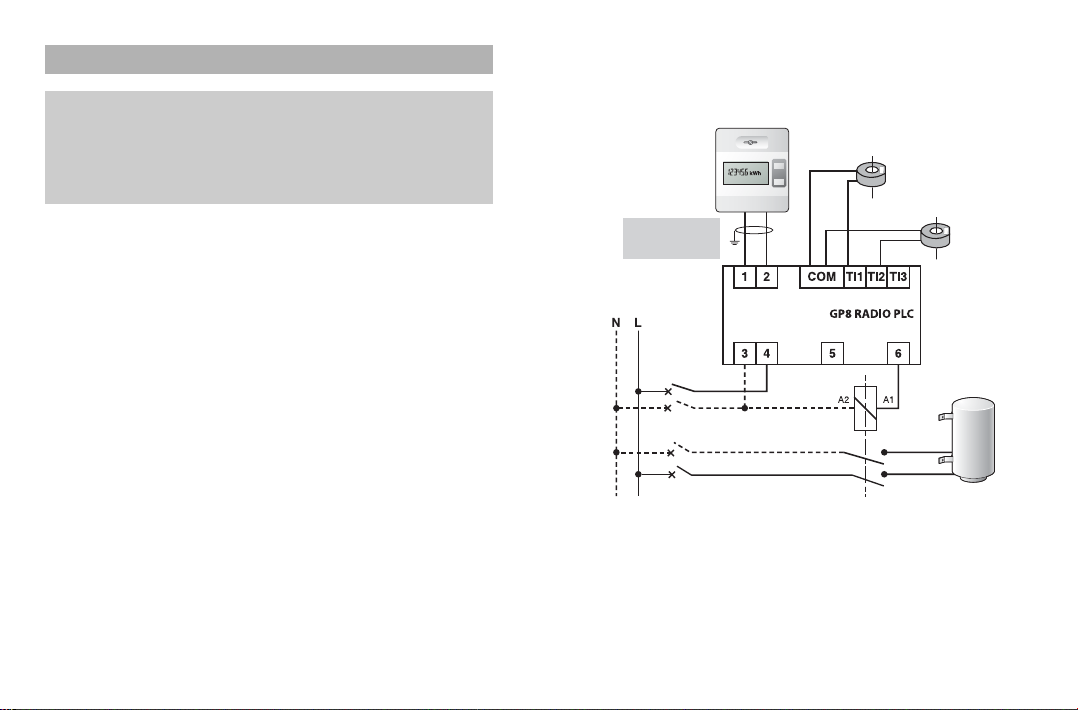
Connecting the GP8 RADIO PLC
Note: Please use at least a 10 A circuit breaker to
protect the power supply
of the GP8 RADIO PLC.
230 V supplied between terminals 3 and 4.The
powerline carrier signals are received and transmitted
through these terminals
.
Installation with an electronic meter
10A
Heating
power supply
Phase CT
Electronic
meter
DHW
power supply
Phase CT
Domestic
HotWater
OP DHW
remote info
230V
power supply
The continuity
wire must
be earthed.
Day/night
contact switch
Current transformers
• The CT wire length can be extended by up to 1.5 m
(for wire type H03VV-F or H05V-K).
• The CT does not have a connection polarity.
• It is possible to pass several conductors from the
same phase through a single CT (maximum interior
Ø10 mm).
• For an installation with a single-phase electronic
meter, the CT option (ref. 6330004) is used for the
consumption indication function of the heating and
DHW consumption types. CT input 3 is not used.
• For an installation with an electromechanical meter,
the CT option is only used for measuring excess con-
sumption for load shedding.
Single-phase: 1 CT
Three-phase: 1 CT per phase (see section on load
shedding)
No consumption meter.

- 8 -
10A
Meter
off-peak contact
T.I.
Domestic
HotWater
OP DHW
remote info
230V
power supply
Day/night
contact switch
Installation with an electromechanical meter
Connecting the GP8 RADIO PLC
- 9 -
10A
L1 L2 L3
L1 L2 L3
Meter
off-peak
contact
The phase connected to the meter's Off-Peak
contact must be the same as the
GP8 RADIO PLC power supply phase.
Phase
coupler
123
Domestic
HotWater
OP DHW
remote info
230V
power supply
Day/night
contact switch
Three-phase connection
- 11 -
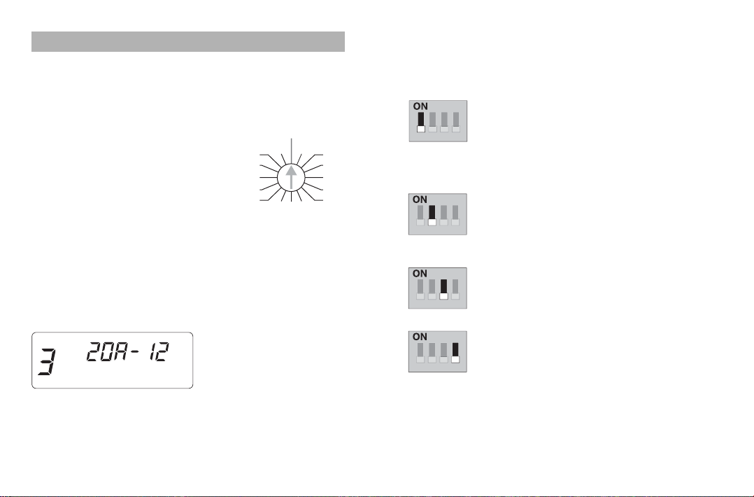
Configuring the load shedding
Load shedding is configured using switches located on
the upper connection terminal of the GP8 RADIOPLC.
Switch 1: Single-phase or three-
phase.
For a three-phase installation with
electromechanical meter, you must have
3 CTs (current transformers).
Switch 2: Load shedding delay.
The load shedding delay (about
3 seconds) is used for applications
featuring a heat pump.
Switch 3: Cascade or cascade-
cyclic load shedding.
See load shedding section.
Switch 4: Load shedding test.
Enables a rapid test of the load
shedding when the system is installed
(load restoration every 3 seconds).
Must be reset to NORMAL after the
test.
(Load shedding time 1 to 2 minutes).
To perform the load shedding test, the
system must be put into power over-
load.
1234
-
3~
-
1~
1234
-
Delayed
-
Immediate
1234
-
Cascade
-
Cascade-cyclic
1234
-
Test
-
Normal
- 10 -
Commissioning the GP8 RADIO PLC
Calibre selection
If your installation is equipped with a
conventional meter, select one of
the calibres available (from 5A to
90A) depending on your specific
EDF subscription.
If your installation is equipped with
an electronic meter, set the switch
to CE (electronic meter).
The calibre that is used is directly
programmed on the meter.
For a three-phase installation, the
calibre chosen is that of the current available for each
phase (and not for the 3 phases).
e.g. Subscribed power (in amperes or in kVA)
Electronic meter display
kVA
15
50
45 35 30 25
20
60
63 10
75 7,5
90 5
CE
40Amp.
Circuit
breaker calibre
- 13 -
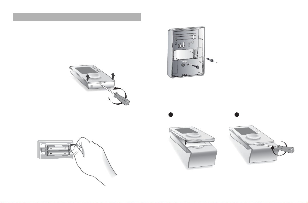
Attachment with screws
Attach the base unit using
screws and plugs suitable for
the mounting surface or to a
flush-mounting box, then close
and lock the unit.
Fitting the unit to its base
Position the unit on its base and lock it.
Position the thermostat
on itsbaseLock the thermostat
1 2
- 12 -
Mounting/Positioning the RADIO DRIVER
For ease of use, the RADIO•DRIVER can be installed:
- on the wall, at a height of about 1.5 m, with
screws/plugs,
- on a base, placed on a piece of furniture or on a
shelf.
Separate the unit
from its base by
unlocking it.
Starting up
Remove the protective tab from the batteries.
The first time you activate the unit, you must set the
clock.

N.B.: For three-phase systems, you must allocate to the
load shedding channels:
- d1 and d2, components powered by phase 1,
- d3 and d4, components powered by phase 2,
- d5, d6, d7 and d8, components powered by phase 3.
- 14 - - 15 -
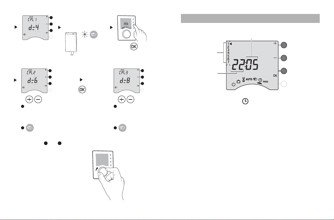
Press
Press and hold the
button for 5 seconds
Turn
the dial to
Press Press
Press twice
Press
OK
OK
RF
RF
GP8 RADIO CPL
Amp.
15
50
45
35 3025
20
60
63 10
75 7,5
90 5
CE
40
RF
RF
Press
The RF
LED flashes
Press
(see section on load
shedding channels)
Load shedding
channel selection
Press and hold
for 3seconds
until the following
screen appears
Quick association of the GP8 PLC to the Radio Driver and PLC receivers
PLC
zone 1 PLC
zone 2 PLC
zone 3
d0
d1
d2
d3
d4
d5
d6
d7
d8
Kitchen
Lounge
Living
room
Living
room 1
Corridor 1Corridor 2
Bedroom
1
Bedroom
2
Bath-
room 1
Bath-
room 2
d0
d1
d2
d3
d4
d5
d6
d7
d8
PLC
zone 1 PLC
zone 2 PLC
zone 3
Load shedding channels
For each receiver, you must specify the programming zone
with which it is to be associated as well as its load shed-
ding channel (from d1 to d8, d0 = no load shedding).
Configuration
example Your configuration
- 17 -- 16 -
Turn the selector dial to .
The days flash.
Press + or - to set the day, then OK to confirm and go
to the next setting.
Repeat these steps to set the hours and minutes.
To exit the “time setting” mode, turn the selector dial.
Setting the time on the RADIO DRIVER
Minutes
Hours
Days
(1: Monday
to 7: Sunday)
to configure
zone 3
to configure
zone 2
Validate on
the receiver
Put the receiver
in association mode
(see documentation)
Validate on
the receiver
Load shedding
channel selection
for zone 2
Repeat stepsand for each receiver in the zone.
To exit the configuration menu,
turn the dial.
1
1 2
2
Validate on
the receiver
Load shedding
channel selection
for zone 3
1
2
Press

To enter the configuration menus,
turn the dial to ,
then press and hold
the ibutton for
5 seconds.
The unit will offer a choice of 4 configurations:
- 18 -
Configuration
Consumption meter
configuration (Menu3)*
Basic configurations(Menu1)
Unit reference (example: RADIO DRIVER 630)
Advanced configurations(Menu2)
Wireless association
Information about unit version
Configuration mode
5 seconds
*Menu 3 is only accessible if the RADIO DRIVER is
associated with a RADIO TYWATT or the consumption
meter function of a GP8 RADIO PLC (see menu R).
- 19 -
Basic configurations (menu 1)
Press the 1button.
To modify the various settings, press the + or - buttons,
then press the OK button to confirm and go to the next
setting.
Programming
type selection
Weekly (default)
Daily
Programming
increment
selection
1 hour (default)
30 minutes
15 minutes
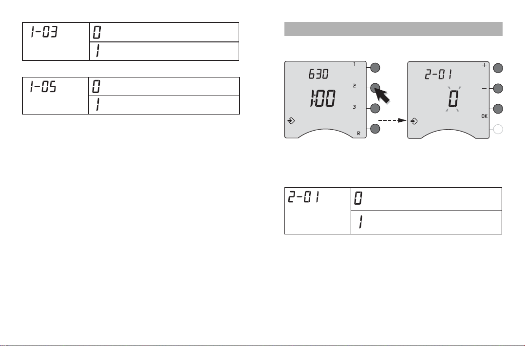
Press the 2button.
To modify the various settings, press the + or - buttons,
then press the OK button to confirm and go to the next
setting.
Change
permission
for user
Programme changesallowed
Programme changesnot allowed
- 21 -
Advanced configurations (menu 2)
- 20 -
Pilot Wire
type selection
6-order Pilot Wire (default)
4-order Pilot Wire
After defining the settings for menu 1, the unit goes back
to the list of menus.
If you want to exit configuration, turn the selector dial to
the right.
DHW status in
absence mode
DHW off (default)
DHW in automatic
- 23 -
With the tempo rate
Specific to and compatible only with the French elec-
tronic meter
Tariff programming is used to select a lower tempera-
ture (reduced rate) in periods when electricity is most
expensive (e.g. peak hours, red day).
The electronic meter informs the GP8 RADIO PLC of
the current price using the remote info line.
Periods of tariff reduction can be programmed on your
electronic meter (refer to the meter’s instructions).
Tariff reduction
selection in
Comfort mode.
Economy (default)
Modérato (Comfort -2 °C)
Médio (Comfort -1 °C)
Comfort (no reduction)
Advanced configurations (menu 2)
- 22 -
Pilot Wire* order
selection in
Economy mode.
*only for 6-order PilotWire
Economy (default)
Modérato (Comfort -2 °C)
Médio (Comfort -1 °C)
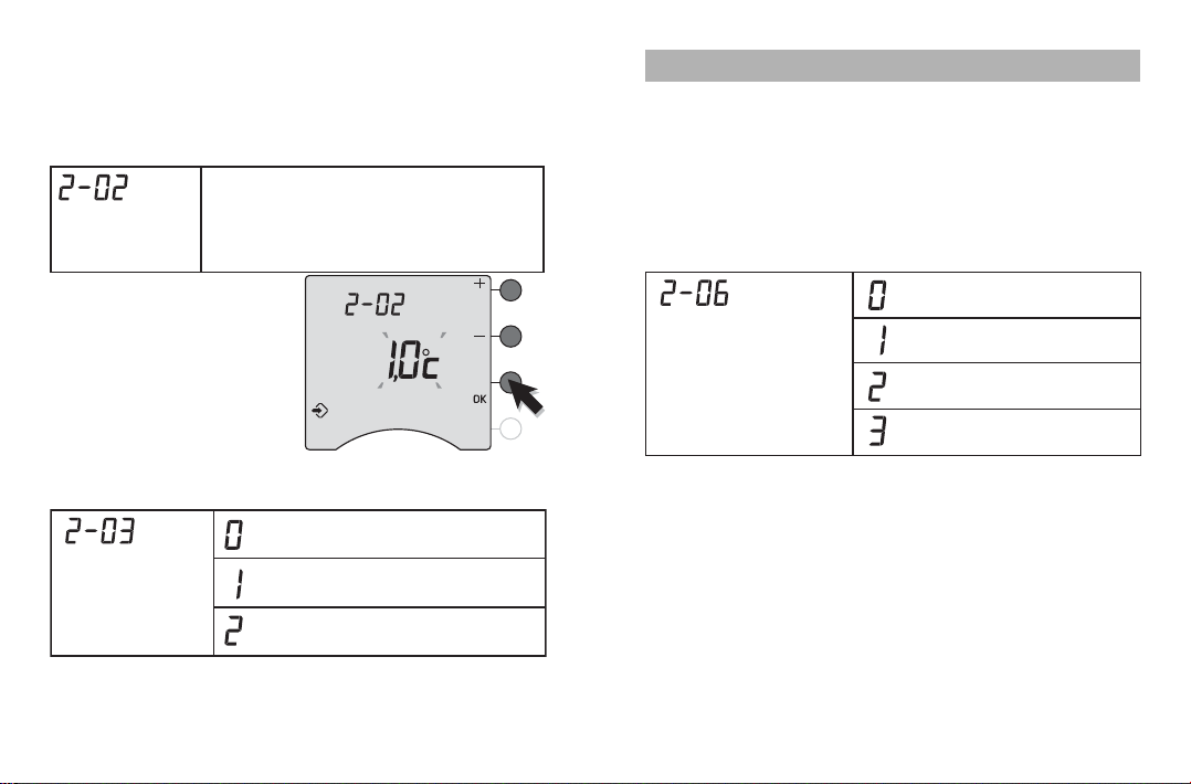
Correction of
temperature
measured
Correction possible by 5 °C either way in
incrementsof 0.1 °C.
Press the + or - buttonsto change and
press OK to confirm.
If there is a difference between the actual temperature
(taken with a thermometer) and the temperature meas-
ured and displayed by the unit, function 2-02 can be
used to compensate for the difference by changing the
way the sensor takes measurements.
Example:
if the temperature dis-
played by the unit is 19 °C
and the actual temperature
is 20 °C, adjust by +1 °C
and press OK to confirm.
Specific to and compatible only with the French elec-
tronic meter
Whatever the choice, the screen will display the symbol .
- 25 -
Wireless/PLC association (menu R)
This menu lets you associate all the installation’s
wireless products (transmitters and receivers) with the
RADIO DRIVER.
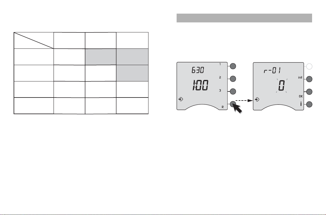
Enter the wireless association menu
Press button R.
- 24 -
In the 2-06 configuration, the tariff reduction mode
can never be lower than parameter 2.03 (see table):
Temporal
Eco
Tariff
reduction
Economy
(Configuration 2-06 = 0)
Comfort - 2°C
(Configuration 2-06 = 1)
Comfort - 1°C
(Configuration 2-06 = 2)
Comfort
(Configuration 2-06 = 3)
Economy
(Configuration
2-03= 0)
Comfort - 2°C
(Configuration
2-03= 1)
Comfort - 1°C
(Configuration
2-03= 21)
Economy
Comfort - 2°C
Comfort - 1°C
Comfort - 1°C
Comfort
Comfort - 1°C
Comfort - 2°C
Comfort Comfort
Comfort - 2°C Comfort - 1°C
Comfort - 1°C
After defining the settings for menu 2, the unit goes back
to the list of menus.
If you want to exit configuration, turn the selector dial to
the right.

Wireless/PLC association (menu R)
- 27 -
“Consumption meter” function
If the GP8 RADIO PLC is connected to the electronic
meter, you have access to consumption indication.
Press + or – to make your choice.
Press OK to confirm and go to the next menu.
Consumption
meter function
No consumption indication
Consumption meter
- 26 -
Home automation functions in the
installation
Up to 7 home automation products (alarm control unit,
remote controls, etc.) can be associated for each of the
heating zones + 7 products to act on all the heating
zones (telephone transmitter, outdoor probe, etc.).
Menu r-01 can be used to declare these home automa-
tion functions.
Compatibility with transmitters from the TYXAL, TYXIA
and TYDOM ranges (Delta Dore).
Press + or – to make your choice.
Press OK to confirm and go to the next mode.
Home automation
functionson the
installation
No home automation functions
Home automation functions
associated with the RADIO DRIVER

Wireless/PLC association (menu R)
- 29 -
Associating a radio transmitter
Step 1: Associate the GP8 RADIO PLC with the
RADIO DRIVER.
Press the button on
the GP8 RADIO PLC for
3 seconds until the RF
LED flashes slowly.
Press and release the i
button on the RADIO
DRIVER.
The screen displays 1.
The GP8 RADIO PLC is
associated with the
RADIO DRIVER.
If you do not have any home automation products,
press the OK button until PLC is displayed and
associate the PLC products.
- 28 -
Access to PLC configuration
The GP8 RADIO PLC controls PLC receivers.
Press + or – to make your choice.
Press OK to confirm and go to the next menu.
Access to PLC
configuration
No PLC configuration
Access to PLC configuration
Wireless/PLC association (menu R)
- 31 -
Transmitter Association
To be associated zone by zone or
for all zones (rAd)
Press the button.
123
456
789
0#
To be associated with all zones
(rAd)
Enter the first 4 numbers of the
access code (1234 by default),
then press the button
for 5 seconds.
To be associated zone by zone
Simultaneously press and hold the
ON•and OFF buttons of the unit’s
control device for 5 seconds to switch
to maintenance mode.
Open up the control unit and press
“test”.
Close the control unit.
Door/window
opening detector
Window open:
heating in Frost Protection
mode
Telephone
transmitter
Remote control
of the installation
TYXAL
control unit
• Monitoring
alarm on: heating in
Economy mode*
• Monitoring alarm off:
heating in Comfort mode*
*: until the next program
change
- 30 -
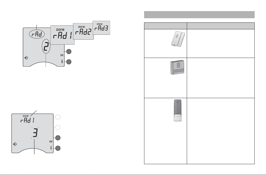
Step 2: Associating the home automation products.
The following menus are used to associate one or
more transmitters, either with all zones (rAd) or with
one zone (zone rAd 1, zone rAd 2 or zone rAd 3).
Select the zone to associate by pressing OK.
On the transmitter,
confirm the association as
indicated in the table or
refer to the user guide.
Each newly associated
transmitter is displayed on
the screen (number of
transmitters).
All zones
Number of associated transmitters
Zone 1
Number of associated transmitters

Wireless/PLC association (menu R)
- 33 -
Associating PLC transmitters
In PLC association, the OK LED of the GP8 RADIO
PLC flashes.
After a few seconds, the screen displays GE
(GP8 RADIO PLC present).
To associate a TYPHONE PLC, please consult its
instructions.
The association is indicated on the tLGE screen.
Press OK to move on to associating PLC receivers.
To remove the association with a TYPHONE PLC,
press init.
Associated
PLCTyphone GP8 RADIO PLC
present
In this menu, no action is needed on the GP8 RADIO
PLC.
- 32 -
Transmitter Association
Press the domain button until the
remote control emits a beep and
the symbol flashes.
Associate buttons and zone by
zone.
Press one of the tactile keys or .
Associate buttons and for all
zones (rAd)
Press one of the tactile keys or .
To exit the association mode, press anoth-
er domain button (e.g. )
To be associated zone by zone
Simultaneously press and hold the
buttons for 5 seconds.The LED comes
on, goes off and then comes back on.
Then release the buttons.
To be associated with all zones (rAd)
Open the sensor’s casing.
Press the association button.
The red LED will switch on then off.
Close the sensor’s casing.
Home automation
remote control
Comfort or Economy
override
TYXIA remote
control
Comfort or Economy
override
Outdoor
sensor
Indication of
the outdoor
temperature
Once the radio associations are made, press the OK button to
confirm and go on to the next mode.

Wireless/PLC association (menu R)
- 35 -
If more than one receiver is associated with the same
programming zone, it is recommended that they each
be given a separate load shedding channel to prevent
simultaneous load shedding (see section on load shed-
ding).
Press OK to select the programming zone (PLC zone
1, PLC zone 2 or PLC zone 3).
Press + or - to select the load shedding channel.
To exit configuration mode, turn the selector dial to the
right.
Example:
Receivers A and B are associated with PLC zone 1.
Receiver A: load shedding channel 1
Receiver B: load shedding channel 2
- 34 -
Associating PLC receivers (e.g. TC 51089)
For each receiver, you must specify the programming
zone with which it is to be associated as well as its
load shedding channel (from d1 to d8, d0 = no load
shedding).
Programming zone
Load sheddin
g
channel
Load shedding
channel selection
Programming
zone selection
Allocation of receivers on a
three-phase system
In three-phase installations, you must assign:
- the components powered by phase 1 to
load shedding channels d1 and d2,
- the components powered by phase 2 to
load shedding channels d3 and d4,
- the components powered by phase 3 to
load shedding channels d5, d6, d7 and d8.
As a priority, the GP8 RADIO PLC resets the phases
not affected by load shedding.

- 37 -
Re-associating a PLC receiver
For example, to modify its load shedding channel.
• Set the transmitter to PLC association mode
(zone + load shedding channel).
• Press and hold the button on the receiver for
5 seconds until the OK LED begins to flash slowly.
• Press and release button on the receiver.
The OK LED comes on steady. The receiver is
associated.
Associating a PLC receiver for DHW control
To control the hot water tank using a suitable PLC
receiver (e.g.TC 51098).
From the PLC DHW screen.
On the receiver, the OK LED
flashes slowly.
Press and release the
button.
The green LED stops
flashing
.
The receiver is associated
with the system.
To exit configuration mode, turn the selector dial to the
right.
Wireless/PLC association (menu R)
Associating receiver A.
Programming zone selected: PLC 1.
Press + or -to select the load shed-
ding channel: d=1.
On the receiver, the OK LED
flashes slowly.
Press and release the button.
The green LED stops flashing.
Receiver A is associated with PLC•zone 1 and load
shedding channel d1.
Associating receiver B.
Programming zone selected: PLC 1.
Press + or -to select the load shed-
ding channel: d=2
On the receiver, the OK LED
flashes slowly.
Press and release the button.
The green LED stops flashing.
Receiver B is associated with PLC•zone 1 and load
shedding channel d2.
- 36 -

Configuration of the consumption meter function
(Menu 3)
- 39 -
3-13 to 3-18 kWh cost (incl. tax)
The price displayed is the price per kWh (exclusive of
subscription) expressed in euros including tax (price
including city and local taxes and VAT (30% on
average)).
For more information, contact your electricity supplier.
It is modified in increments of 1 euro cent.
We recommend rounding to the nearest cent.
For example: Euro 0.1085 is rounded to Euro 0.11.
€0.11 (incl. tax)
- 38 -
Configuration of the consumption meter function
(Menu 3)
Only if the GP8 RADIO PLC is connected to an elec-
tronic meter.
Menus 3-12 to 3-18 are only available if you have
declared the consumption meter function in menu R
(r-02).
Consumption meter function
To display consumptions for heating, DHW and other
uses, you must declare the number of CTs (current
transformers, ref. 6330004) associated with the GP8
RADIO PLC option.
Number of CTs
No partial consumption indication
1 CT (Heating)
2 CTs(Heating + DHW)
Not used
Table of contents
Popular Heating System manuals by other brands

ITR
ITR Hurricane Zephyr HW Installation and operating manual

Graco
Graco REACTOR E-XP1 troubleshooting guide

Panasonic
Panasonic WH-ADC0509L3E5 Service manual

Yellow Diving
Yellow Diving THERMOV Manual And Maintenance Directions

Napoleon
Napoleon Galaxy Series Installation and operation manual

Swegon
Swegon CLASS UNIT Operation & maintenance instructions


System air
System air Villavent VR 400 DC User and maintenance instructions

Heatline
Heatline Retro-DWS installation instructions

Delta
Delta K160 user manual

Süd wind
Süd wind Ambientika SOLO INSTALLATION, USE AND MANTEINANCE MANUAL

System air
System air VR 400 DCV installation instructions

VOGEL&NOOT
VOGEL&NOOT KONTEC KS Series installation instructions