Delta Elektronika PSC-ETH-2 User manual

DELTA
ELEKTRONIKA B.V.
Vissersdijk 4, 4301 ND www.DeltaPowerSupplies.com
DC POWER SUPPLIES
Zierikzee, the Netherlands Tel. +31 111 413656
PSC-ETH-2
PSC-ETH-2 INT
Internal interface Card
PSC-ETH-2 EXT
External Interface Module
PRODUCT MANUAL
Firmware version P0102
Contents:
1–In General
2–Installation
3–Communication
4–Downloads & Web Interface
5 –Conventions
6 –Command description
7 –Sequencer
8 –Command list TCP/IP
9 –Command list Sequencer
10 –EU Declaration
Firmware Update
It is strongly recommended, first to perform a firmware update before further
operation. See this manual for instructions.
Driver & Example Software
For several applications and Interfaces there is Driver & Example Software
available on our website. See PRODUCTS\PSC-ETH\DOWNLOADS.
Your distributor:

Product Manual PSC-ETH-2
2 / 38 DELTA ELEKTRONIKA B.V. Preliminary version Dec. 2019
Table of Contents
1In General ................................................................................................................................................4
1.1 Features .................................................................................................................................................................................4
1.2 Analog....................................................................................................................................................................................4
1.3 Status.....................................................................................................................................................................................4
1.4 LEDs.......................................................................................................................................................................................4
1.5 Digital I/O................................................................................................................................................................................5
1.5.1 User Inputs (connector CON F): ..............................................................................................................................................5
1.5.2 User Outputs (connector CON G):...........................................................................................................................................5
2Installation...............................................................................................................................................6
2.1 Infrastructure.........................................................................................................................................................................6
2.2 Software.................................................................................................................................................................................6
2.3 Settings..................................................................................................................................................................................6
2.4 Terminal.................................................................................................................................................................................7
2.5 DE Easy Control ....................................................................................................................................................................7
3Communication.......................................................................................................................................8
3.1 Settings..................................................................................................................................................................................8
3.2 TCP/IP.....................................................................................................................................................................................8
4Downloads & Web Interface ..................................................................................................................9
4.1 Firmware updating.................................................................................................................................................................9
4.2 Firmware ................................................................................................................................................................................9
4.3 Web Interface.........................................................................................................................................................................9
4.3.1 Console...................................................................................................................................................................................9
4.3.2 Configuration.........................................................................................................................................................................10
4.3.3 Administration........................................................................................................................................................................11
4.3.4 Documentation......................................................................................................................................................................11
4.3.5 Ethernet.................................................................................................................................................................................11
4.3.6 Sequencer.............................................................................................................................................................................11
4.4 Forgotten password, access key or network settings ......................................................................................................11
5Conventions ..........................................................................................................................................12
5.1 Syntax ..................................................................................................................................................................................12
5.2 Query....................................................................................................................................................................................12
5.3 Space <sp> ..........................................................................................................................................................................12
5.4 Terminator <term>...............................................................................................................................................................12
5.5 Parameters...........................................................................................................................................................................12
6Command description..........................................................................................................................13
6.1 General Instructions............................................................................................................................................................13
6.1.1 *IDN?.....................................................................................................................................................................................13
6.1.2 *PUD.....................................................................................................................................................................................13
6.1.3 *SAV......................................................................................................................................................................................13
6.1.4 *RST......................................................................................................................................................................................13
6.1.5 *RCL......................................................................................................................................................................................14
6.2 Source Subsystem ..............................................................................................................................................................14
6.2.1 Introduction............................................................................................................................................................................14
6.2.2 Maximum Output Voltage ......................................................................................................................................................14
6.2.3 Maximum Output Current.......................................................................................................................................................14
6.2.4 Set Output Voltage................................................................................................................................................................14
6.2.5 Set Output Current ................................................................................................................................................................14
6.2.6 Output Voltage Stepsize........................................................................................................................................................14
6.2.7 Output Current Stepsize........................................................................................................................................................14
6.3 Measure Subsystem............................................................................................................................................................15
6.3.1 Introduction............................................................................................................................................................................15
6.3.2 Measure Output Voltage........................................................................................................................................................15
6.3.3 Measure Output Current........................................................................................................................................................15
6.3.4 Measure Output Power..........................................................................................................................................................15
6.4 Calibrate Subsystem ...........................................................................................................................................................15
6.4.1 Introduction............................................................................................................................................................................15
6.4.2 Definitions..............................................................................................................................................................................16
6.4.3 Set A: compatible with PSC ETH...........................................................................................................................................16
6.4.4 Set B: compatible with PSC-ETH-2 / SM-Series....................................................................................................................17
6.5 Digital User In-/Outputs.......................................................................................................................................................18
6.5.1 User Outputs.........................................................................................................................................................................18
6.5.2 User Inputs............................................................................................................................................................................18
6.6 System Subsystem..............................................................................................................................................................18
6.6.1 Remote Shut Down (RSD).....................................................................................................................................................18
6.6.2 Limits.....................................................................................................................................................................................19
6.6.3 Front Panel Lock ...................................................................................................................................................................19
6.6.4 Remote programming............................................................................................................................................................19
6.6.5 Error Message.......................................................................................................................................................................20
6.6.6 Password ..............................................................................................................................................................................20
6.6.7 Watchdog..............................................................................................................................................................................20
6.6.8 Terminator.............................................................................................................................................................................21
6.7 Output ..................................................................................................................................................................................22
6.8 Register Structure...............................................................................................................................................................22
6.8.1 *CLS......................................................................................................................................................................................22
6.8.2 User Input Registers..............................................................................................................................................................22
7Sequencer..............................................................................................................................................23

Product Manual PSC-ETH-2
3 / 38 DELTA ELEKTRONIKA B.V. Preliminary version Dec. 2019
7.1 Introduction .........................................................................................................................................................................23
7.2 Commands...........................................................................................................................................................................23
7.2.1 Settings.................................................................................................................................................................................23
7.2.2 Jumps....................................................................................................................................................................................23
7.2.3 Arithmetic ..............................................................................................................................................................................24
7.2.4 Miscellaneous........................................................................................................................................................................25
7.3 Sequence control by commands........................................................................................................................................26
7.3.1 Read the Catalog...................................................................................................................................................................26
7.3.2 How to create or select a Sequence ......................................................................................................................................26
7.3.3 Upload a Sequence to PSC-ETH-2 (PC →PS) .....................................................................................................................26
7.3.4 Download a Sequence from PSC-ETH-2 (PS →PC).............................................................................................................26
7.3.5 Delete a Sequence................................................................................................................................................................26
7.3.6 Start a Sequence...................................................................................................................................................................26
7.3.7 Pause a Sequence................................................................................................................................................................26
7.3.8 Step through a Sequence......................................................................................................................................................26
7.3.9 Stop a Sequence...................................................................................................................................................................27
7.3.10 Read Sequence mode......................................................................................................................................................27
7.3.11 Trigger a Step...................................................................................................................................................................27
7.3.12 Add labels.........................................................................................................................................................................27
7.3.13 Delete labels.....................................................................................................................................................................27
7.3.14 Building a Sequence.........................................................................................................................................................27
7.3.15 Select saving to non-volatile memory................................................................................................................................28
7.3.16 Saving to non-volatile memory..........................................................................................................................................28
7.4 Sequence control by Web...................................................................................................................................................28
7.4.1 Read the Catalog...................................................................................................................................................................28
7.4.2 How to create a sequence.....................................................................................................................................................29
7.4.3 How to select a sequence......................................................................................................................................................29
7.4.4 Upload a sequence to PSC-ETH-2 (PC →PS)......................................................................................................................29
7.4.5 Download a Sequence from PSC-ETH-2 (PS →PC).............................................................................................................30
7.4.6 Delete a Sequence................................................................................................................................................................30
7.4.7 Start a Sequence...................................................................................................................................................................30
7.4.8 Pause a Sequence................................................................................................................................................................30
7.4.9 Step through a Sequence......................................................................................................................................................30
7.4.10 Stop a Sequence..............................................................................................................................................................30
7.4.11 Read Sequence mode......................................................................................................................................................30
7.4.12 Trigger a Step...................................................................................................................................................................30
7.4.13 Add labels.........................................................................................................................................................................30
7.4.14 Delete labels.....................................................................................................................................................................30
7.4.15 Building a Sequence.........................................................................................................................................................30
7.4.16 Saving a sequence to non-volatile memory.......................................................................................................................31
7.5 Sequence control by user inputs .......................................................................................................................................31
7.6 Sequence examples ............................................................................................................................................................32
7.6.1 Example 1: Generate waveform.............................................................................................................................................32
7.6.2 Example 2: Test relays..........................................................................................................................................................33
8Command list TCP/IP............................................................................................................................34
8.1 Index TCP / IP ......................................................................................................................................................................34
9Command list Sequencer.....................................................................................................................36
9.1 Index Sequencer..................................................................................................................................................................36
10 EU-Declaration of Conformity .........................................................................................................38

Product Manual PSC-ETH-2
4 / 38 DELTA ELEKTRONIKA B.V. Preliminary version Dec. 2019
1In General
1.1 Features
The PSC-ETH-2 is an interface between a TCP/IP network and a Power Supply. It allows the operator to
create fully automated systems. The PSC-ETH-2 can set and measure the parameters of the power supply,
read the status, set controls, interact with digital I/O and generate waveforms, stored in memory. It is even
possible to take over tasks from a PLC. That makes processes and test systems more powerful and less
complex.
1.2 Analog
The power supplies of Delta Elektronika are very stable and accurate. The PSC-ETH-2 is designed
especially for these kinds of power supplies. Therefore the programming and measuring resolution is 16
bits and all units are calibrated very precisely by the factory (if unit and PSC are bought together).
To calculate the step size in Voltage or Ampere, use the equation below:
1.3 Status
The power supplies are equipped with a lot of signals which inform the user about the status of the supply.
Status like Limit, OverTemperature, DCF, etc. can be read to check the condition of the system.
For example, ACF-signal (which indicates an incorrect input voltage) can be monitored, so action can be
taken to avoid problems before a system is switched off.
1.4 LEDs
Inside the RJ45 connector are two LEDs, see picture below.
The left orange LED is named "ERR". When this LED is ON, the Ethernet interface has generated an error
message as a result of a bad command or parameter.
The right Green LED is named "LNK/ACT", which stands for Link/Activity. This LED indicates whether or
not the Ethernet interface is connected and communicates.
Product Manual PSC-ETH-2
5 / 38 DELTA ELEKTRONIKA B.V. Preliminary version Dec. 2019
1.5 Digital I/O
The SM800, SM1500, SM6000 and the external PSC-ETH-2 provide 8 user inputs and 8 outputs. These
can be controlled / monitored by commands (refer to chapter 5) or can be used to interact with the
Sequencer (refer to chapter 6) to make the power supply act like a power PLC.
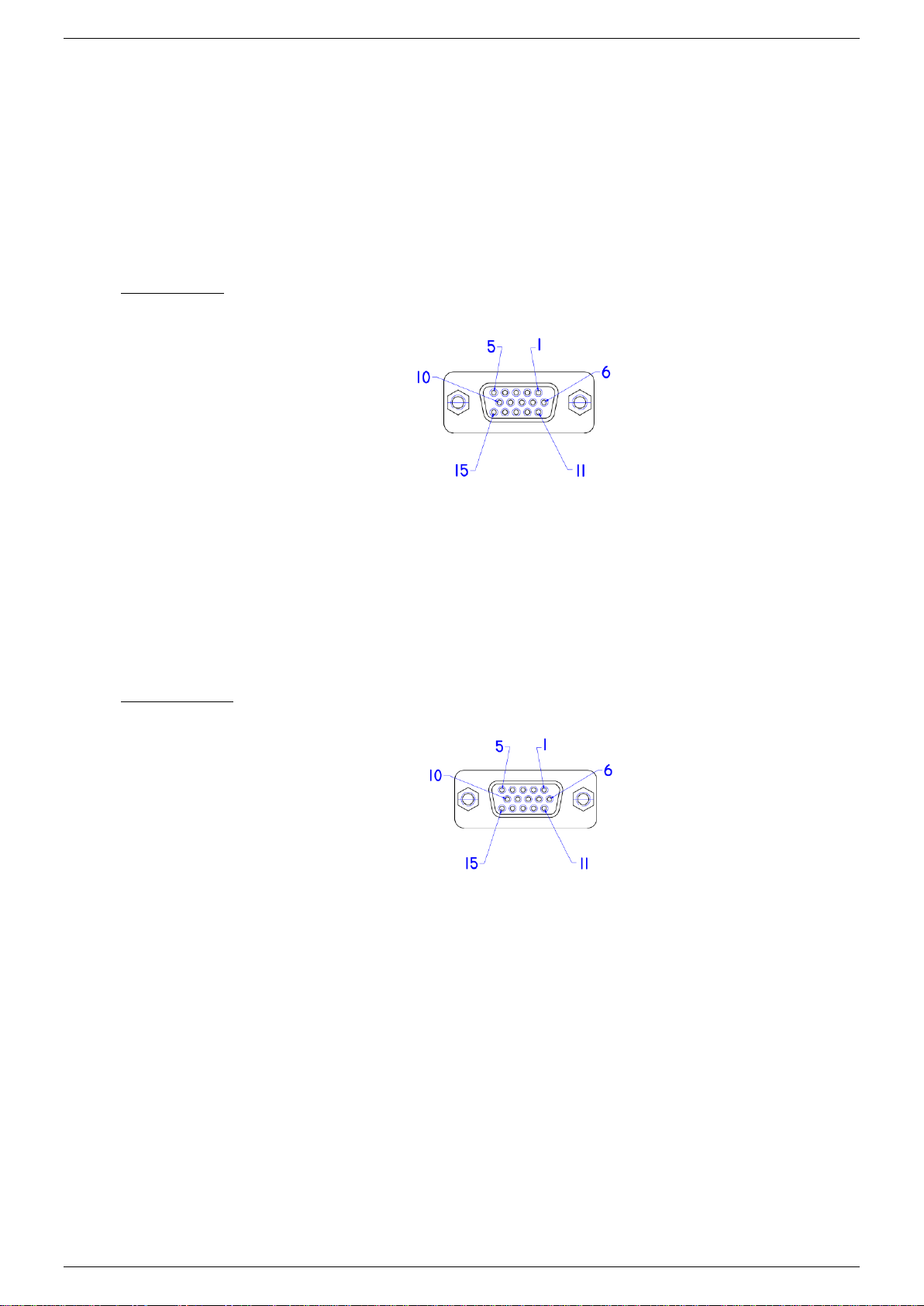
1.5.1 User Inputs (connector CON F):
Unconnected inputs are LOW. To make an input HIGH, apply the +5V of pin 9 or pin 14. Also an external
voltage can be used to control the inputs. Make sure the common of the external source is connected to pin
10 or pin 15.
The user inputs have a working range of 2.5 V - 30 V and have an internal impedance of approximately
2kOhms. The maximum load of the +5V is 100mA.
Con F (female)
1 = user input A
2 = user input B
3 = user input C
4 = user input D
5 = user input E
6 = user input F
7 = user input G
8 = user input H
9 = +5V
10 = 0V
11 = n.c.
12 = n.c.
13 = n.c.
14 = +5V
15 = 0V
1.5.2 User Outputs (connector CON G):
The 8 user outputs are open collector. When an output is TRUE, it is pulled down to 0V. Otherwise the
output is open. Check the datasheet for maximum voltage and sink current of the user outputs.
CON G (female)
1 = user output A
2 = user output B
3 = user output C
4 = user output D
5 = user output E
6 = user output F
7 = user output G
8 = user output H
9 = +5 V
10 = 0 V
11 = n.c.
12 = n.c.
13 = n.c.
14 = +5 V
15 = 0 V

Product Manual PSC-ETH-2
6 / 38 DELTA ELEKTRONIKA B.V. Preliminary version Dec. 2019
2Installation
2.1 Infrastructure
To control or program the power supply, the Ethernet interface should be connected to a TCP/IP network,
using the RJ45 connector at the rear (connector LAN). A standard RJ45 patch- or cross-link cable can be
used to connect the Ethernet interface to a network switch, or directly to a PC. The Ethernet interface is
Auto-MDIX. This means that for example a patch cable can be used for a direct connection, instead of
using a cross-link cable. The "LNK"- LED of the Ethernet interface will be on when the connection is okay.
Either Cross-Link or standard Ethernet cable can be used.
The command "PING <address>" can be used (e.g. via Windows© menu Start - RUN - CMD) to check the
connection. For example: PING 10.1.0.101.
2.2 Software
On our website, go to PRODUCTS > INTERFACES > PSC ETH INTERFACE > DOWNLOADS and
download the "Software Ethernet Interface" for installation and applications.
2.3 Settings
Each network has its own range of IP addresses. To be able to control the PSC-ETH-2 via a particular
network, the IP address of the PSC-ETH-2 must be within the address range of that network.
The setup installs a program named "PSC-ETH Configurator". This program shows the IP addresses of
the PSC-ETH-2s connected to the network and allows to change it. It also shows the MAC address, the
serial number and the identification string (*PUD) of every PSC-ETH-2.
By clicking on (one of) the PSC-ETH-2(s), the user can set the IP address, the default gateway and the IP
address mask.
Recommended address ranges are:
Class A: 10.0.0.0 to 10.255.255.255 (mask: 255.0.0.0)
Class B: 172.16.0.0 to 172.31.255.255 (mask: 255.240.0.0)
Class C: 192.168.0.0 to 192.168.255.255 (mask: 255.255.0.0)
with the exception of all addresses ending with '0' or '255'.
Warning: Addresses above 223.255.255.255 are not supported on several operating systems; the PSC-
ETH-2 will be out of range. That is why this program blocks these address settings.
When IP-settings are unknown, press the reset button next to the ETH connector. See paragraph 4.4 for
details.
When more PSC-ETH-2 devices are used, it is recommended to give them specific names, using the
command *PUD (refer to chapter 6.1).
Warning!
Carefully read the chapter "Safety Instructions" in the Delta Elektronika power supply manual before connecting the internal ETH
Interface or the external ETH module!
With regards safety, the Ethernet connector, the User I/O connectors and the Analog Programming connector (only on the external
module) are all at the level of the ‘minus’ DC power terminal of the unit. The power output is floating in relation to the Protective
Earth and can be at a hazardous high voltage!
When the ‘minus’ DC power terminal of the unit can exceed 60Vdc / 42.4Vpk in respect to Protective Earth, additional external
measures must be taken to ensure safety isolation PSC-Ethernet connections.

Product Manual PSC-ETH-2
7 / 38 DELTA ELEKTRONIKA B.V. Preliminary version Dec. 2019
2.4 Terminal
The setup also installs a program named "PSC-ETH Terminal". This program can be used to send
commands to and read queries from the PSC-ETH-2 easily. Very useful for checking the connection or to
send commands manually.
After installation, this program can be found under "Programs \ Delta Elektronika". First set the right IP
address in the "IP address"-box. Then type a command (e.g. *IDN?) in the "Characters to Write"-box and
click on the "Send"-button.
The commands to be sent are checked for a question mark. If present, the terminal waits for the answer
from the PSC-ETH-2, identified with an "auto query" LED on the screen after a command is send. The
answer appears in the "Characters Read"-box.
2.5 DE Easy Control
During setup you can choose to install a program called "DE Easy Control". This is a graphical user
interface that resembles the front panel of the power supply. The program can be used to set and monitor
the output of the power supply.
By clicking the arrow button of the "unit" drop down menu in the upper right corner of the program a scan is
started for any power supply with a PSC-ETH-2 connected to the PC. (The connection can be a direct link
or via a network.) The result of the scan is shown in a list which contains the IP addresses, PUD strings,
Serial numbers or MAC addresses of the interfaces. From this list a power supply can be selected. The
identifier shown in the list (IP, PUD, Serial or MAC) depends on the selected option in the programs upper
right corner.
The appearance of the user interface depends on the specifications and features or the selected power
supply. This means that the scale of the voltage and current knobs will automatically adjust to the
maximum allowed values stored in the PSC-ETH-2. The status indicators will appear or disappear
automatically as well, depending on the features that the power supply offers.
The settings for both voltage and current can be changed by turning the knobs or by entering the required
value in the boxes below the knobs. The measured value is shown in the displays above the knobs.
To run the program, the "LabVIEW Run-Time Engine 2015" is required. (Copyright © 2015 National
Instruments Corporation. All rights reserved.) This Run-Time Engine is included in the downloadable
software package on the website. It can also be downloaded from www.ni.com.
Disclaimer
This software is provided by Delta Elektronika B.V. “as is” without guarantee. The usage of this software is at own risk. In no event
shall Delta Elektronika BV be liable for any damage as a result from the use, misuse, inability to use, faulty operation, installation or
adjustments of the software. Delta Elektronika does not accept any responsibility with regards to losses of the owner or third party
users as a result of the usage of this software.

Product Manual PSC-ETH-2
8 / 38 DELTA ELEKTRONIKA B.V. Preliminary version Dec. 2019
3Communication
3.1 Settings
There are two important settings to communicate properly with the PSC-ETH-2, which are:
IP address: default 10.1.0.101. Can be freely configured by the user (refer to section 2.2).
Port number: fixed to 8462.
3.2 TCP/IP
Any programming language or application that can send and receive TCP/IP packages can be used for
communication with the PSC-ETH-2. To show the user / programmer how to communicate with the PSC-
ETH-2, examples of LabVIEW are provided on the website.
Disclaimer
This software is provided by Delta Elektronika B.V. “as is” without guarantee. The usage of this software is at own risk. In no event
shall Delta Elektronika BV be liable for any damage as a result from the use, misuse, inability to use, faulty operation, installation or
adjustments of the software. Delta Elektronika does not accept any responsibility with regards to losses of the owner or third party
users as a result of the usage of this software.
Product Manual PSC-ETH-2
9 / 38 DELTA ELEKTRONIKA B.V. Preliminary version Dec. 2019
4Downloads & Web Interface
4.1 Firmware updating
Check the version of the firmware in the unit via Menu > System Info > Unit > Version.
Go to www.DeltaPowerSupplies.com and check if there is new firmware available via Products -> PSC-
ETH -> Downloads. Download the new firmware package to the computer.
Connect the unit to the above computer via LAN and open the PSC-ETH-2 web interface using an internet
browser.
The web interface is found by entering the IP-address of the unit in the address bar of the browser.
Note: when DHCP is enabled the IP-address can change, for example after a power cycle.
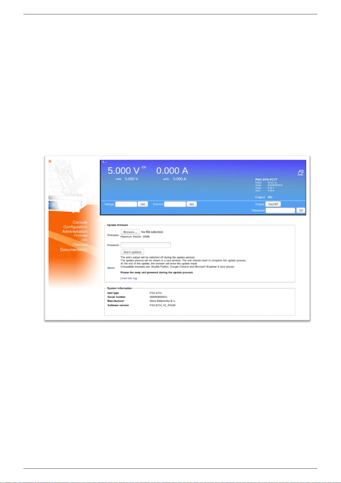
In the web interface, go to Administration -> Firmware.
Select "Choose File" and browse to the downloaded package, enter password if enabled and "Start
Update". See below figure 4 - 1 for a screen shot of the web interface.
Recommended firmware package is P0100.
*Note: when DHCP is enabled, the IP-address can change, for example after a power cycle.
4.2 Firmware
Check at www.DeltaPowerSupplies.com for latest firmware via:
Products > PSC-ETH > Downloads.
Note: This document is based on firmware version 0102. It is strongly recommended to regularly check for updates for
additional functionality and improvements.
4.3 Web Interface
It is advised to use the web browsers Mozilla Firefox, Google Chrome or MS Edge or later.
The web interface is available 15 seconds after start up of the unit.
The below menu items are available in the web interface:
4.3.1 Console
4.3.1.1 Frontpanel
Possible settings via the console:
- voltage and current
- output On/Off
Fig. 4 - 1 - Regularly check for new versions of user manual and firmware.

Product Manual PSC-ETH-2
10 / 38 DELTA ELEKTRONIKA B.V. Preliminary version Dec. 2019
Possible monitoring via the console:
- actual and set values of voltage and current
- output setting (on/off)
- status icons, for example DC-fail
- type of unit and serial number
See fig. 4 - 2 for the console lay-out.
4.3.1.2 Sequencer
Possible to select sequences from the unit memory.
Running, Pausing and Stopping of sequences.
Trigger sequence
Running in Single Step mode.
Monitor sequencer variables and timers via the "advanced" button.
See fig 4 - 3 for the console lay-out.
4.3.2 Configuration
4.3.2.1 General
LIMITS
Switch Voltage Limit ON or OFF and set value.
Switch Current Limits ON or OFF and set values.
SOURCES
Set the program source for voltage control.
Set the program source for current control.
NETWORK
DHCP enabled / disabled.
IP Version.
Network IP address.
Network Subnet mask.
Network Gateway address.
Network interface MAC address.
SEQUENCES
Upload sequences into the unit's volatile memory.
Synchronize memory to copy sequences from the volatile to the non-volatile memory.
After switching off the unit, the sequences remain on the power supply.
Monitor and make settings:
- View sequencer name
- View if it is loaded as active sequencer
- View if it has been build
Fig. 4 - 2 - Front console for setting of the output and monitoring various parameters.
Fig. 4 - 3 - Sequencer console for selecting and controlling sequences.

Product Manual PSC-ETH-2
11 / 38 DELTA ELEKTRONIKA B.V. Preliminary version Dec. 2019
- Mark for Non-Volatile
- Set start/stop conditions
- Set if to restore or retain output state and values after it is terminated
- Mark for deletion
See paragraph "SEQUENCER" in this chapter for more information about sequencer programming.
4.3.3 Administration
4.3.3.1 Firmware
Here a new firmware package can be uploaded.
4.3.3.2 Info
System information
- Unit.
- Serial number.
- Manufacturer.
- Software version.
4.3.3.3 Password
Change the password to block the unit.
The default password is "depower".
Passwords are not case sensitive.
In case of a forgotten password see next paragraph in this chapter.
4.3.4 Documentation
Unit documentation in PDF-format available:
- Safety instructions.
- Ethernet & Sequencer programming manual.
4.3.5 Ethernet
The ETH interface is available 15s after start up of the unit.
Connect the unit to the network via the LAN-connector at the rear.
Set the programming source for voltage and/or current to 'eth' via the eth commands or the web interface.
4.3.6 Sequencer
Define a sequence using a basic text editor, for example Notepad. Save as "filename.seq". An example is
shown in chapter 7 of this manual. Upload the sequence via the web interface or via Eth programming
commands.
Set the programming source for voltage and/or current to 'seq' via the web interface or Eth commands.
Start/Stop the sequence via the web interface, Eth commands or a hardware trigger via the Digital I/O
interface.
Note: copy the uploaded sequences into the non-volatile memory before switching off the unit. Standard they are
uploaded in the volatile memory and are lost after switching off the mains.
4.4 Forgotten password, access key or network settings
To reset the password and the network settings to their default values, press the reset button at the rear
panel of the unit (while the unit is switched on).
A bent paperclip can be used to press the internal micro push button. A soft sensible click can be noticed.
Press and hold the button for at least 4 seconds in order to activate the default restoring mechanism.

Product Manual PSC-ETH-2
12 / 38 DELTA ELEKTRONIKA B.V. Preliminary version Dec. 2019
5Conventions
The PSC-ETH-2 has a command set, which includes commands compatible with the SCPI language
(Standard Commands for Programmable Instruments).
5.1 Syntax
The command descriptions contain the syntax of the instructions and show the form in which these
commands can be sent to the PSC-ETH-2.
It is allowed either to use the short form or the entire command.
For example : SOURce:VOLtage<sp>5<term> can be send as :
sour:vol<sp>5<term>
source:volt<sp>5<term>
source:voltage<sp>5<term>
sour:voltage<sp>5<term>
SoUrCe:VoLt<sp>5<term>
(Sending mixed upper- and lowercase is allowed).
5.2 Query
Commands ending with a question mark "?" (ASCII character 3FH, 63d) are interpreted as a
query. If it is a valid command, the unit will respond with an answer. Otherwise an error is
generated.
5.3 Space <sp>
Within the syntax spaces are used, indicated by <sp>, which is equal to ASCII character 20H (32d).
5.4 Terminator <term>
At the end of each command or query, a terminator character is required, indicated by <term>.
Each reply on a valid query will end with <term>.
Default terminator is a linefeed (ASCII character OAH, 10d).
For other terminator options see paragraph 6.6.8, sub-paragraph "Terminator".
5.5 Parameters
Within this document, parameters are used to indicate the form of data sent to or coming from the PSC-
ETH-2.
<NR1> = positive integers: 0,1,2,3,...
<NR2> = floating point : 3.22, 0.06, etc.
<boolean> = False or True parameter : 0 or 1, OFF or ON.
[ ] = It is allowed to use or to skip this part of the command.

Product Manual PSC-ETH-2
13 / 38 DELTA ELEKTRONIKA B.V. Preliminary version Dec. 2019
6Command description
6.1 General Instructions
6.1.1 *IDN?
This command is used to read the identification string of the PSC-ETH-2. The string contains the name, the
option number, the version of the firmware and the serial number of the PSC.
Syntax: *IDN?<term>
The response string has 4 fields, separated by commas.
For example:
DELTA<sp>ELEKTRONIKA<sp>BV,PSC<sp>ETH<sp>P157<sp>V1.0.0,449101000099,0<term>
The first field shows the manufacturer's name.
The second field shows: interface name (PSC ETH) + option name (P157) + firmware version.
The third field shows the serial number of the PSC-ETH-2 interface.
The last field is reserved for future implementations.
6.1.2 *PUD
PUD is an abbreviation for Protected User Data. This command allows the user to give the power supply
his own name for identification or to store relevant data.
For example names like "Motor Controller Setup 3", "Battery Simulator" or "Calibrated March 14 2019".
This information can be maximum 72 characters long and is stored into non-volatile memory (see
command *SAV).
Syntax: *PUD<sp><data><term> data = A-Z, a-z, 0-9, <sp>, _ and -, 72 maximum
To read the Protected User Data:
Syntax: *PUD?<term>
6.1.3 *SAV
To store all relevant settings, this command saves them into non-volatile memory.
A summary of the saved setting are shown below:
Maximum output voltage : SOURce:VOLTage:MAXimum
Maximum output current : SOURce:CURRent:MAXimum
Calibration gain current setting : CAL 0
Calibration offset current setting : CAL 1
Calibration gain voltage setting : CAL 2
Calibration offset voltage setting : CAL 3
Calibration gain current measure : CAL 4
Calibration gain voltage measure : CAL 5
Calibration offset current measure : CAL 6
Calibration offset voltage measure : CAL 7
Protected User Data : *PUD
Password : SYSTem:PASSword
Syntax: *SAV<term>
When a password is used, the only way to store these relevant settings into memory is to use:
Syntax: *SAV<sp><password><term>
Warning: this command overrides the settings already stored in memory.
6.1.4 *RST
This reset command sets the power supply in a save defined state. The table below gives an overview of
the settings made after sending this reset command or after power-on of the PSC-ETH-2:
Setting Value set after *RST: set after power-on:
Setting
Value
set after *RST:
set after power-on:
SOURce:VOLTage
0
YES
YES
SOURce:CURRent
0
YES
YES
SYSTem:RSD
OFF
YES
YES
SYSTem:REM
REM
YES
NO
SYSTem:REM:CV
REM
YES
NO

Product Manual PSC-ETH-2
14 / 38 DELTA ELEKTRONIKA B.V. Preliminary version Dec. 2019
SYSTem:REM:CC
REM
YES
NO
SYSTem:FRONtpanel
OFF
YES
NO
OUTPut
OFF
YES
NO
Table 6.1
6.1.5 *RCL
This command recalls calibration settings and the Protected User Data. This can be used in case of
accidental override of these settings.
Syntax:*RCL<term>
6.2 Source Subsystem
6.2.1 Introduction
First of all the PSC-ETH-2 should know which type of power supply it will be controlling. Therefore two
commands are available to set the maximum output voltage and the maximum output current. Default
settings are 5V / 5 A. These settings must be changed for correct operation. When the PSC-ETH-2 is built-
in by Delta Elektronika B.V., these settings are already done.
Both parameters (output voltage and output current) have a working range from 0 to the maximum output
voltage / current of the power supply.
The response strings contain a floating point value with 4 digits of precision.
6.2.2 Maximum Output Voltage
To set the maximum output voltage of the power supply, this command must be sent. Refer to section 6.1.3
how to save this setting to the non-volatile memory.
Syntax:SOURce:VOLTage:MAXimum<sp><NR2><term>
e.g. <NR2> is 30 for an SM30-200 power supply.
To read the last settings, send the query:
Syntax:SOURce:VOLTage:MAXimum?<term>
For example the answer is: 30.0000<term>
6.2.3 Maximum Output Current
To set the maximum output current of the power supply, this command must be sent. Refer to section 6.1.3
how to save this setting to the non-volatile memory.
Syntax:SOURce:CURRent:MAXimum<sp><NR2><term>
where e.g. <NR2> is 200 for an SM30-200 power supply.
To read the last settings, send the query:
Syntax:SOURce:CURRent:MAXimum?<term>
6.2.4 Set Output Voltage
To set the output voltage of the power supply:
Syntax:SOURce:VOLTage<sp><NR2><term>
To read the last settings, send the query:
Syntax:SOURce:VOLTage?<term>
6.2.5 Set Output Current
To set the output current of the power supply:
Syntax:SOURce:CURRent<sp><NR2><term>
To read the last settings, send the query:
Syntax:SOURce:CURRent?<term>
6.2.6 Output Voltage Stepsize
To read the programming stepsize of the output voltage, send the query:
Syntax : SOURce:VOLtage:STEpsize?<term>
The reply will be in scientific notation, with an accuracy of 15 decimals, e.g.:
1.055924221873283e-03<term>
This represents the smallest Voltage programming step possible.
6.2.7 Output Current Stepsize
To read the programming stepsize of the output current, send the query:
Syntax : SOURce:CURrent:STEpsize?<term>
The reply will be in scientific notation, with an accuracy of 15 decimals, e.g.:
1.759365200996399e-03<term>
This represents the smallest Current programming step possible.

Product Manual PSC-ETH-2
15 / 38 DELTA ELEKTRONIKA B.V. Preliminary version Dec. 2019
6.3 Measure Subsystem
6.3.1 Introduction
To measure the power supply output parameters Voltage, Current and Power, three different queries are
available.
These commands measure the actual output parameters, which are not necessarily the same as the output
settings SOURce:VOLTage and SOURre:CURRent.
If for example the output settings are 15 V and 5 A and the unit is in CC-mode (Constant Current), the
output voltage is not equal to the setting of 15 V, but less.
6.3.2 Measure Output Voltage
To measure the output voltage of the power supply:
Syntax:MEASure:VOLTage?<term>
6.3.3 Measure Output Current
To measure the output current of the power supply:
Syntax:MEASure:CURRent?<term>
6.3.4 Measure Output Power
To measure the output power of the power supply, send this query. (Actually this command executes
MEASure:VOLTage and MEASure:CURRent, multiplies the results and returns the output power in Watts)
Syntax:MEASure:POWer?<term>
6.4 Calibrate Subsystem
6.4.1 Introduction
To make the accuracy of the PSC-ETH-2 / power supply combination as high as possible, it is required to
calibrate the PSC-ETH-2 first. There are eight parameters to calibrate. Four related to the voltage settings /
measurements and four related to the current settings / measurements.
The calibration settings are already done, when the PSC-ETH-2 is built-in by Delta Elektronika B.V.
However, periodical check and calibration is recommended.
At power-on the calibration settings are restored.
For proper calibration it is recommended to use this order (an SM60-100 is used as example) :
- Set output voltage of the power supply to e.g. 1% of the maximum output voltage.
SOUR:VOLT<sp>0.6<term>
- Calibrate the source voltage offset, so the output voltage is as close as possible to 0.6 V
- Calibrate the measure voltage offset, so the result of the command MEASure:VOLTage? is as
close as possible to 0.6 V.
- Set the output voltage to maximum
- Calibrate the source voltage gain, so the output voltage is as close as possible to the
maximum voltage, 60 V.
- Calibrate the measure voltage gain, so the result of the command MEASure:VOLTage? is as
close as possible to the actual output voltage, 60 V.
Same principle is used for the current calibration.
Default settings for the offsets are 0, and default settings for the gains are 1. The resolution of both settings
and readings are 6 digits.
Notice. Both gain and offset changes influence the actual output parameter. After changing offset, check if
the gain has to change. And vise versa. To get a very accurate result, redo the calibration a few times.
There are 2 sets of commands to perform the calibration.
Set A is compatible with the first version of the PSC-ETH card.
Set B is compatible with the modern commands that are used in the latest SM-series.
Note that both sets have their own equations for the offset calculation.
Both sets of commands, A and B, can be used in a mixed way. There is no strict need or recommendation
to choose for a certain set of commands.

Product Manual PSC-ETH-2
16 / 38 DELTA ELEKTRONIKA B.V. Preliminary version Dec. 2019
6.4.2 Definitions
6.4.2.1 Programmed Value
The setting applied via web or SOURce:VOLTage or SOURce:CURRent.
6.4.2.2 Actual Value
The real output voltage or current measured with external instruments.
6.4.2.3 Measured Value
The response of MEASure:VOLTage? or MEASure:CURRent?.
6.4.3 Set A: compatible with PSC ETH
For SOURCE offset calibration, use the equation:
For SOURCE gain calibration, use the equation:
For MEASURE offset calibration, use the equation:
For MEASURE gain calibration, use the equation:
To save the calibration settings to the non-volatile memory, refer to section 6.1.
6.4.3.1 Calibrate Gain Source Current
To calibrate the programming gain of the current setting:
Syntax:CAL<sp>0,<NR2><term>
To read the calibration settings:
Syntax:CAL<sp>0?<term>
6.4.3.2 Calibrate Offset Source Current
To calibrate the programming offset of the current setting:
Syntax:CAL<sp>1,<NR2><term>
To read the calibration settings:
Syntax:CAL<sp>1?<term>
6.4.3.3 Calibrate Gain Source Voltage
To calibrate the programming gain of the voltage setting:
Syntax:CAL<sp>2,<NR2><term>
To read the calibration settings:
Syntax:CAL<sp>2?<term>
6.4.3.4 Calibrate Offset Source Voltage
To calibrate the programming offset of the voltage setting:
Syntax:CAL<sp>3,<NR2><term>
To read the calibration settings:
Syntax:CAL<sp>3?<term>
6.4.3.5 Calibrate Gain Measure Current
To calibrate the gain of the current measurement:
Syntax:CAL<sp>4,<NR2><term>
To read the calibration settings:
Syntax:CAL<sp>4?<term>

Product Manual PSC-ETH-2
17 / 38 DELTA ELEKTRONIKA B.V. Preliminary version Dec. 2019
6.4.3.6 Calibrate Gain Measure Voltage
To calibrate the gain of the voltage measurement:
Syntax:CAL<sp>5,<NR2><term>
To read the calibration settings:
Syntax:CAL<sp>5?<term>
6.4.3.7 Calibrate Offset Measure Current
To calibrate the offset of the current measurement:
Syntax:CAL<sp>6,<NR2><term>
To read the calibration settings:
Syntax:CAL<sp>6?<term>
6.4.3.8 Calibrate Offset Measure Voltage
To calibrate the offset of the voltage measurement:
Syntax:CAL<sp>7,<NR2><term>
To read the calibration settings:
Syntax:CAL<sp>7?<term>
6.4.4 Set B: compatible with PSC-ETH-2 / SM-Series
For SOURCE offset calibration, use the equation:
For SOURCE gain calibration, use the equation:
For MEASURE offset calibration, use the equation:
For MEASURE gain calibration, use the equation:
To save the calibration settings to the non-volatile memory, refer to section 6.1.
6.4.4.1 Calibrate Gain Source Current
To calibrate the gain of the current setting:
Syntax:CALIbrate:CURrent:GAIn<sp><NR2><term>
To read the calibration settings:
Syntax:CALIbrate:CURrent:GAIn?<term>
6.4.4.2 Calibrate Gain Source Voltage
To calibrate the gain of the voltage setting:
Syntax:CALIbrate:VOLtage:GAIn<sp><NR2><term>
To read the calibration settings:
Syntax:CALIbrate:VOLtage:GAIn?<term>
6.4.4.3 Calibrate Offset Source Current
To calibrate the offset of the current setting:
Syntax:CALIbrate:CURrent:OFFset<sp><NR2><term>
To read the calibration settings:
Syntax:CALIbrate:CURrent:OFFset?<term>
6.4.4.4 Calibrate Offset Source Voltage
To calibrate the offset of the voltage setting:
Syntax:CALIbrate:VOLtage:OFFset<sp><NR2><term>
To read the calibration settings:
Syntax:CALIbrate:VOLtage:OFFset?<term>

Product Manual PSC-ETH-2
18 / 38 DELTA ELEKTRONIKA B.V. Preliminary version Dec. 2019
6.4.4.5 Calibrate Gain Measure Current
To calibrate the gain of the current measurement:
Syntax:CALIbrate:CURrent:MEAsure:GAIn<sp><NR2><term>
To read the calibration settings:
Syntax:CALIbrate:CURrent:MEAsure:GAIn?<term>
6.4.4.6 Calibrate Gain Measure Voltage
To calibrate the gain of the voltage measurement:
Syntax:CALIbrate:VOLtage:MEAsure:GAIn<sp><NR2><term>
To read the calibration settings:
Syntax:CALIbrate:VOLtage:MEAsure:GAIn?<term>
6.4.4.7 Calibrate Offset Measure Current
To calibrate the offset of the current measurement:
Syntax:CALIbrate:CURrent:MEAsure:OFFset<sp><NR2><term>
To read the calibration settings:
Syntax:CALIbrate:CURrent:MEAsure:OFFset?<term>
6.4.4.8 Calibrate Offset Measure Voltage
To calibrate the offset of the voltage measurement:
Syntax:CALIbrate:VOLtage:MEAsure:OFFset<sp><NR2><term>
To read the calibration settings:
Syntax:CALIbrate:VOLtage:MEAsure:OFFset?<term>
6.5 Digital User In-/Outputs
The SM800, SM1500, SM6000 and the external PSC-ETH-2 provide 8 user inputs and 8 outputs. These
can be controlled / monitored by commands (explained below) or can be used to interact with the
Sequencer (refer to chapter 7).
6.5.1 User Outputs
To program the user outputs, a decimal number can be send to the PSC-ETH-2. This decimal number
represents the binary state of the 8 user outputs.
Syntax:UOUTput<sp><0+NR1><term> 0+NR1= 0,1,2,3.....255
Output A = 1
Output B = 2
Output C = 4
Output D = 8
Output E = 16
Output F = 32
Output G = 64
Output H = 128
For example, to set output C and F, send UOUTput<sp><36><term>. (=4+32)
To reset all the user outputs, send UOUTput<sp><0><term> (default setting after power-on).
To read the last setting of the user outputs:
Syntax:UOUTput?<term>
6.5.2 User Inputs
To read the status of the 8 user inputs, the User Input Condition Register can be read:
Syntax:UINPut:CONDition?<term>
The PSC-ETH-2 will return a decimal number, which represents the binary status of the 8 inputs.
Input A = 1
Input B = 2
Input C = 4
Input D = 8
Input E = 16
Input F = 32
Input G = 64
Input H = 128
For example, if only Input A and Input G are high, the condition will be : 65<term>. (=1+64)
6.6 System Subsystem
6.6.1 Remote Shut Down (RSD)
Syntax:SYSTem:RSD[:STATus]<sp><boolean><term> boolean = 0, 1, OFF, ON

Product Manual PSC-ETH-2
19 / 38 DELTA ELEKTRONIKA B.V. Preliminary version Dec. 2019
To read the last setting:
Syntax:SYSTem:RSD[:STATus]?<term>
6.6.2 Limits
To set the limits of the voltage:
Syntax:SYSTem:LIMits:VOLtage<sp><NR2>,<boolean><term> Off = disabled, On = enabled
To read the last setting:
Syntax:SYSTem:LIMits:VOLtage?
To set the limits of the current:
Syntax:SYSTem:LIMits:CURrent<sp><NR2>,<boolean><term> Off = disabled, On = enabled
To read the last setting:
Syntax:SYSTem:LIMits:CURrent?
6.6.3 Front Panel Lock
This command is only available for PSC-ETH-2, which are built inside a power supply with internal CPU;
SM800, SM1500 and SM6000.
Syntax:SYSTem:FRONtpanel[:STATus]<sp><boolean><term> boolean = 0, 1, OFF, ON
To read the last setting:
Syntax:SYSTem:FRONtpanel[:STATus]?<term>
6.6.4 Remote programming
The built-in PSC-ETH-2 allows the user to switch to either LOCAL or REMOTE programming.
There are two different methods to select the programming source, depending on the type of power supply.
Check below table 5.2.
6.6.4.1 Remote method 1
With this method the two programming signals CV and CC are switched simultaneously.
Syntax:SYSTem:REMote[:STATus]<sp><setting><term> setting = REMote or LOCal1
To read the last setting:
Syntax:SYSTem:REMote[:STATus]?<term>
6.6.4.2 Remote method 2
This method provides to switch CV or CC programming individually, so one of the two can be controlled via
the PSC-ETH-2 and the other one via the pot-meter on the front panel. Any combination is possible. Hence
there are two commands to set the programming source:
To set the CV programming source:
Syntax:SYSTem:REMote:CV[:STATus]<sp><setting><term> setting = REMote or LOCal1
To read the last setting:
Syntax:SYSTem:REMote:CV[:STATus]?<term>
To set the CC programming source:
Syntax:SYSTem:REMote:CC[:STATus]<sp><setting><term> setting = REMote or LOCal1
To read the last setting:
Syntax:SYSTem:REMote:CC[:STATus]?<term>
1) The settings Remote or Local are equal to the settings Ethernet or Front.
Possible settings are: Front (Local), Web, Sequencer or Ethernet (Remote).
Type of unit
REMOTE
REMOTE:CV
REMOTE:CC
External
no
no
no
ES150
no
no
no
ES300
no
no
no
SM800
no
yes
yes
SM1500
no
yes
yes
SM6000
no
yes
yes
SM1500-1 * Obsolete
(no longer manufactured)
yes
no
no
SM3000 Obsolete
(no longer manufactured)
no
no
no
* SM1500-1 can be recognized by it's mains toggle switch; instead of a rotary switch.
Table 6.2

Product Manual PSC-ETH-2
20 / 38 DELTA ELEKTRONIKA B.V. Preliminary version Dec. 2019
6.6.5 Error Message
If an unknown command, an invalid value or an illegal setting is received by the PSC-ETH-2 an error is
generated. The user is prompted by the Error LED on the RJ45 connector and an error message is stored
in the error queue, which contains the error number and a description of the kind of error.
The error queue can contain maximum 10 errors; more error messages are ignored. The command to read
the queue line by line is:
Syntax : SYSTem:ERRor?<term>
The PSC-ETH-2 returns the first error and clears it from the queue. If there are no errors (so the queue is
empty), the result of this query will be : 0,None<term>
So after 10 readings of SYSTem:ERRor? the queue is empty for sure, or after using the *CLS command.
6.6.6 Password
To protect the most essential settings of the system (calibration values, *PUD, password) a password can
be used. The default password is : "depower".
To apply a password, send the command:
Syntax : SYSTem:PASsword<sp><old_password>,<new_password><term>
If no password is used, <old_password> must be "default" (case independent) and <new_password> the
password to be used.
To remove the password, <old_password> must be the current password and <new_password> must be
"default" (case independent).
Maximum length of password is 9 characters.
Note: When a password is unknown or forgotten, the reset switch can be pressed for four seconds. This
will restore the factory default password. The Network settings will also be set to factory default "DHCP
Enable".In the beginning of this manual there is a detailed description about the reset switch.
To store the new password, refer to section 6.1.3 (*SAV)
To read if a password is used, send the query
Syntax : SYSTem:PASsword:STAtus?<term>
If no password is used, the PSC-ETH-2 will return 0<term>, otherwise it returns 1<term>.
6.6.7 Watchdog
The PSC-ETH-2 provides a Watchdog timer on the Ethernet interface. The PSC-ETH-2 monitors the
Ethernet communication when set and disables its power output when no Ethernet command is received
within the time set.
The Watchdog timer is disabled after a power-on event. Send the set command once to activate the
Watchdog timer and reset the timer by sending any valid Ethernet command at regular intervals.
To set the Watchdog timer (in ms):
Syntax : SYSTem:COMmunicate:WATchdog<sp>SET,<NR1><term> <NR1>= 20…10000
To read the last setting: (valid until Timeout)
Syntax : SYSTem:COMmunicate:WATchdog<sp>SET?<term>
To read the current state of the Watchdog timer:
Syntax : SYSTem:COMmunicate:WATchdog?<term>
There are three possibilities:
20…10000<term> Current timer value in ms
0<term> Timeout. Clears indicator on the Web
-1<term> Clears Timeout, Watchdog is off
To disable the Watchdog timer:
Syntax : SYSTem:COMmunicate:WATchdog<sp>STOP<term>
To test the Watchdog timer:
Syntax : SYSTem:COMmunicate:WATchdog<sp>TEST<term>
The timer will be set to 2.5ms and expires very quickly. The indicator on the Web will be activated. Enable,
disable or query the state of the Watchdog timer to clear the indicators.
This manual suits for next models
2
Table of contents
Other Delta Elektronika Recording Equipment manuals


Popular Recording Equipment manuals by other brands


 Interface Device NI... quick start guide")


Leviton
Leviton GreenMax DRID0-C02 quick start guide

ARX
ARX Afterburner II owner's manual

Solidyne
Solidyne S-500 series user manual

Allen-Bradley
Allen-Bradley Guardmaster EtherNet/IP 440R-ENETR installation instructions

Extron electronics
Extron electronics HAI 100 4K SETUP INSTRUCTION GUIDE

microHAM
microHAM MK2R user manual