flight of harmony Famine User manual

Voltage-controlled power starvation Eurorack Module kit
v1

FAM1500-K v1.0 manual Jun. 2022 — p.1/15 www.ightofharmony.com
Contents
(1) Front Panel
(1) PCB
(1) Resistor Card
(1) Semiconductor Card
(1) Capacitor Card
(1) Hardware bag
(8) 0.25" QC PCB tabs
(2) 2x8 box header
(2) M3x0.5 eurorack mounting screw
(2) M3 nylon washer
(2) 3mm (T1) LED, red
(1) Wire bag
(8) 13” 18AWG wire (2 each: Green, Red, Black, Blue)
(16) Insulated quick-connect (QC) crimp receptacles
(3) 4" Nylon cable ties
(1) 14"L x 0.125"I.D. Braided wire sleeve
(2) 0.5"L heat-shrink tubing
(1) Potentiometer bag
(2) B10k Potentiometer
(2) Washer
(2) Nut
(2) Knob
(1) Jack bag
(2) 3.5mm TS jack
(2) Washer
(2) Nut
(1) Switch bag
(2) SPDT (Single-Pole, Double-Throw) toggle switch with nut
(1) DPDT (Double-Pole, Double-Throw) toggle switch with nut
(3) 10-40 hex nut
(3) #10 star internal-tooth lock washer
(1) Reference manual (this thing)
(1) Owner's manual (that other thing like this thing)

FAM1500-K v1.0 manual Jun. 2022 — p.2/15 www.ightofharmony.com
Kit Notes
Tools
• Soldering iron with ne tip
• Solder
• Fine-tip tweezers
• Nut drivers/sockets/wrenches:
• 7mm (toggle switch)
• 8mm (jack nuts)
• 10mm (potentiometer nuts)
• Wire strippers
• Insulated connector crimper
Skills
This kit assumes that you have a basic understanding of electronics, electronic
components, and soldering and assembling electronics. Note that this kit is almost
entirely Surface Mount Technology (SMT), so the assumption is that you understand
how to work with Surface Mount Devices (SMD) and have some experience.
This doesn't mean that you're completely on your own, just that I'm not going
to hold your hand1. Below are a few things to help get you started. Feel free to
ignore them.
Assembly Tips
• For the SMD, use the smallest soldering iron tip that you have. My favorite
is the Weller ETR: (Not an endorsement, nor do I get anything from it, it's
just a good reference point.) Remember to switch back to a larger tip when
soldering the through-hole components.
• Good, ne-tip tweezers are a must. The Wiha 4b and 7a tweezers are great2.
• One helpful trick for soldering SMD with wire solder is to pre-solder one pad
for each component location. Next, hold the component in place and touch
1) For many reasons, but two in particular: First, I'd have to leave my house, and I hate doing that.
Second, it's really hard to solder with only one hand.
2) IMO, their 5abb were the best, but they discontinued them so FML. No, you can't have mine.
Narrow Screwdriver
Cat
. A B C
No.
in. mm in. mm in. mm
ETR
0.062 1.60 0.044 1.12 0.625 15.90
A
B
C

FAM1500-K v1.0 manual Jun. 2022 — p.3/15 www.ightofharmony.com
Kit Notes (cont.)
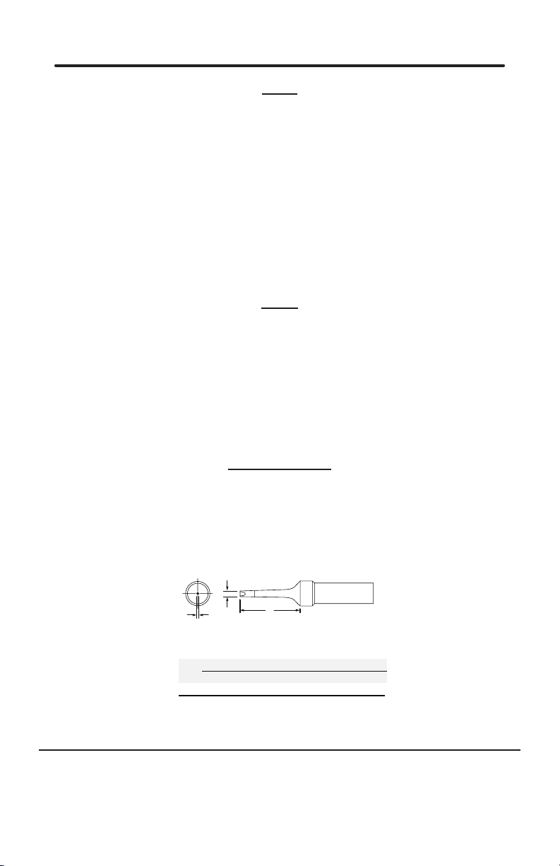
your soldering iron tip to the pre-soldered pad to reow the solder. Then you
can solder the other side normally.
• Flux is your friend. Use ux. Water-soluble ux is best for a clean nish, but
you have to make sure to get it all off when done, as it can corrode the joint
and some uxes may also be capacitive. You can also use no-clean ux.
• Smallest rst. Solder the components in increasing order of size.
• Minimize heat exposure. Heat destroys components, and SMD are particularly
sensitive because they have less mass to distribute the heat. Flux helps with
this too.
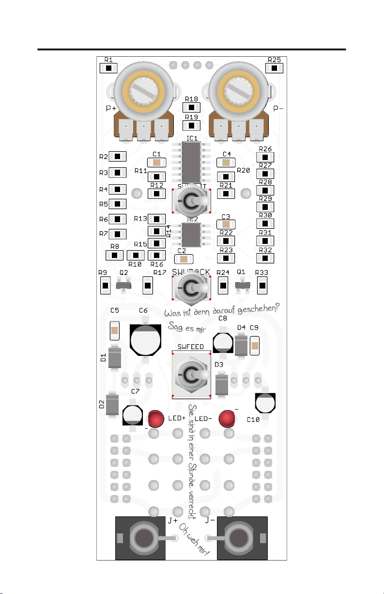
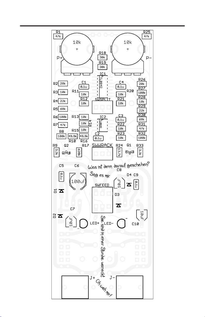
• Use the face plate to line up the potentiometers,jacks, and LEDs, before
soldering; this is much easier than resoldering them to line them up correctly
afterward. You may have to attach and remove the panel a few times with this
kit because of the component density.
Assembly Order
The easiest build order is as follows:
1. All SMD. For the rest, follow the order shown on Page 7:
2. Install & solder the rear chaining header.
3. Install & solder the potentiometers, switches, and LEDs. Trim the LED
leads.
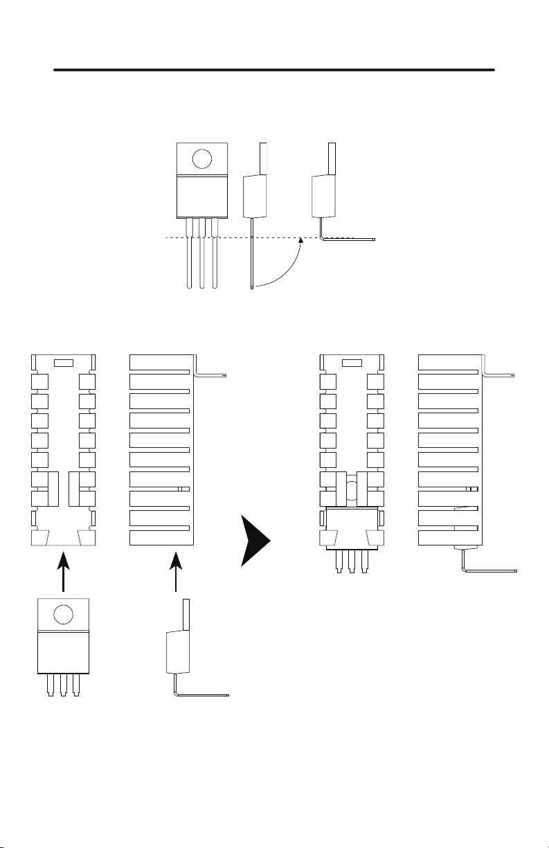
4. Assemble the regulators and heat sinks (see graphic, p.9), then install
them on the PCB. Install & solder the quick-connect tabs.
5. Install & solder the 2x8 shrouded headers. NOTE THE ORIENTATION.
Due to the cramped board layout, there wasn't enough room for the
CV and Gate pins, so they have been removed from the headers (see
graphic p.5).
6. Install & solder the jacks.
7. Attach the panel - see toggle switch jam nut instructions on p.14.
Help
If you're still having problems, email me! I am always happy to help. When
emailing, please include high-resolution pictures of your circuit boards.
Most of the troubleshooting requests I have received were solved by zooming
in and closely examining the pictures. Cold solder joints are sneaky and hard to
spot if you haven't dealt with them before. A cold solder joint is where the solder
doesn't adhere to both the pad and the component lead, and just owed around
one of them without making contact. They happen, and they suck, but they're easy
xes once you nd them.

FAM1500-K v1.0 manual Jun. 2022 — p.4/15 www.ightofharmony.com
PCB Assembled Front View

FAM1500-K v1.0 manual Jun. 2022 — p.5/15 www.ightofharmony.com
PCB Assembled Rear View

FAM1500-K v1.0 manual Jun. 2022 — p.6/15 www.ightofharmony.com
SMD Reference

FAM1500-K v1.0 manual Jun. 2022 — p.7/15 www.ightofharmony.com
Exploded View
3
2
4
6
5
Numbers indicate easiest (in regard to soldering) order of assembly; see
instruction list on p.3.

FAM1500-K v1.0 manual Jun. 2022 — p.8/15 www.ightofharmony.com
LED Installation
Solder rst
Do not solder
Finger-tight
Finger-tight
Set lens to desired
height then solder

FAM1500-K v1.0 manual Jun. 2022 — p.9/15 www.ightofharmony.com
Regulator Installation
Bend line
90°

FAM1500-K v1.0 manual Jun. 2022 — p.10/15 www.ightofharmony.com
Power Cable Assembly
Quick & Easy option
1. Strip about 0.25"/6.5mm from each end of wire.
2. Place quick-connect terminal over end of wire and crimp securely.
3. Use nylon cable ties to keep wires together & orderly.

FAM1500-K v1.0 manual Jun. 2022 — p.11/15 www.ightofharmony.com
Power Cable Assembly
Pretty & Painful option
1. Group the wires together & stagger the ends a bit to give the overall
prole a taper. (If you have some electrical tape, taping the ends together
can make it even easier.)
2. Work the braided sleeving over the wires.
3. Slide heat-shrink tubing over braid. If the braid ends are frayed, wrap
a piece of tape around the circumference to get the tubing over it. Slide
the tubing to the middle of the cable.
4. Separate the wires and strip about 0.25"/6.5mm from each wire end.
5. Place quick-connect terminal over wire ends and crimp securely.
6. Slide heat-shrink tubing towards cable ends until middle of tube is
aligned with end of braided sleeve.
7. Use heat source to shrink tubing. A hot air gun or boiling water1is best,
a lighter or match also work but can leave scorch marks and possibly
melt or ignite the sleeving.
1) Make sure to dry it before use if you use boiling water. Don't use Famine wet.

FAM1500-K v1.0 manual Jun. 2022 — p.12/15 www.ightofharmony.com

FAM1500-K v1.0 manual Jun. 2022 — p.13/15 www.ightofharmony.com
IC Orientation
Diode Orientation
Miscellaneous
LED and capacitor Orientation
(OR) LINE
Pin 1
Line/Slope
Line/Slope

FAM1500-K v1.0 manual Jun. 2022 — p.14/15 www.ightofharmony.com
Spin ush with panel.
Spin ush with panel,
do not tighten.
Tighten gently with
nut driver/wrench/socket.
Tightening toggle switch jam nuts.
Toggle switches are slightly shorter than the jacks and potentiometers, so the
jam nut (rear nut) must be run ush with the panel before tightening the outer nut
to prevent deforming the panel.
Miscellaneous (cont.)

FAM1500-K v1.0 manual Jun. 2022 — p.15/15 www.ightofharmony.com
Table of contents
Other flight of harmony Recording Equipment manuals
Popular Recording Equipment manuals by other brands

Keyautomation
Keyautomation SEL-D Instructions and warnings for installation and use

red lion
red lion KADET 2 G307K2 quick start guide

BENDIXKing
BENDIXKing AeroPanel 100 System installation and operation manual

Data Video
Data Video MS-3200 instruction manual

Blackmagicdesign
Blackmagicdesign Ultimatte 12 Operation manual

BOSSCO
BOSSCO Loop Station RC-20 owner's manual