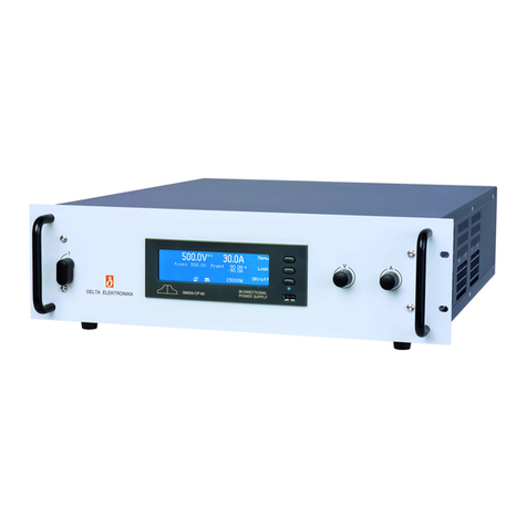
Delta Elektronika INT MOD SIM User manual

SM 3300 - Interfaces
•INT MOD SIM
•INT MOD CON
•INT MOD SER
•INT MOD DIG
•INT MOD ANA


INT MOD SIM Simulation interface
INT MOD CON Isolated contacts interface
INT MOD SER Multi-protocol serial interface
INT MOD DIG Digital I/O interface
INT MOD ANA Isolated analog interface
SM3300 - Interface modules
DELTA ELEKTRONIKA B.V.
Vissersdijk 4
4301 ND Zierikzee
The Netherlands
Tel. +31 111 413656
Fax. +31 111 416919
www.deltapowersupplies.com
Features
•Plug and play for the SM3300 series
power supplies
•Multiple interfaces possible per power supply
•Isolated from the output voltage
Working voltage 1000V
•Floating with respect to earth
Models Description General Features
•High accuracy, low drift
•16 bit AD and DA conversion
•Compatible with other Delta
Elektronika 15p analog interfaces
•Factory calibrated for optimum
accuracy
Analog controller interface
INT MOD ANA
Features
•8 inputs Logic high = 2.5 ... 30V,
Logic low = 0V
•8 Open Drain outputs 0 - 30V, max.
200mA
•Programmable via Ethernet or
sequences
Digital (user) I/O
INT MOD DIG
Features
•4 relays with make-and-break contacts
•Additional (floating) Interlock with
24V enable system
•Programmable via Ethernet
Isolated contacts
INT MOD CON
Features
•Multi protocol RS232, RS485, RS422,
USB
•Web based configuration
•Speeds up to 115.2 kbps
Serial controller interface
INT MOD SER
Features INT MOD SIM
Simulation Interface
•High accuracy simulation
•Simulation of photovoltaic, leadless
sense compensation, internal
resistance and foldback current
•Custom programmable table, for
simulation of complex I-V curves
•Configurable trough web and GUI

DELTA ELEKTRONIKA BV SM3300 INTERFACES
Page 1 - 2 SPECIFICATIONS March 2014
Typical Applications
•Simulation of photovoltaic I-V curve
• Testing dynamic mppt effiency with EN 50530 standard
• Compensation for the voltage drop in the load leads without sense wires
• Custom I-V curve simulation trough custom table
• Simulation of internal resistance
• Simulation of foldback current limit
Simulation Interface
Specifications
Photovoltaic Simulation
Required reference parameters Open circuit voltage (Voc,stc), Maximum power point voltage (Vmpp,stc), Short circuit current (Isc,stc),
Maximum power point current (Impp,stc), Temperature at STC (Tstc), Irradiance at STC (Gstc),
Temperature coefficient for the current (TcIsc), Temperature coefficient for the voltage (TcVoc).
Required panel parameters Technology (cSi or Thin Film), Temperature of the photovoltaic panel (Tpv),
Irradiance on the photovoltaic panel (Gpv).
Required parameters for
dynamic efficiency test
Irradiance high level (Ghigh), Irradiance low level (Glow), Start-up time, Ramp-up time, Dwell-high time,
Ramp-down time, Dwell-low time, Number of repetitions.
Programming accuracy ± 0.2%
Internal Resistance SM 18-220 SM 66-AR-110 SM 100-AR-75 SM 330-AR-22 SM 660-AR-11
Max. configurable Ri13.5 mΩ54.5 mΩ115 mΩ1.35 Ω5.45 Ω
Response time
Ri
Output Voltage (load = 0W)
Output current step
Rise time (10% - 90%)
Fall time (90% - 10%)
13.5 mΩ
16.5 V
20-200 A
3 ms
3 ms
54.5 mΩ
33 / 66 V
10-100 / 5-50 A
1.25 / 1.25 ms
1.25 / 1.25 ms
115 mΩ
50 / 100 V
6.6-66 / 3.3-33 A
2.25 / 2.25 ms
2.25 / 2.25 ms
1.35 mΩ
165 / 330 V
2-20 / 1-10 A
2.25 / 2.25 ms
2.25 / 2.25 ms
5.45 mΩ
330 / 660 V
1-10 / 0.5-5 A
2.5 / 2.25 ms
2.5 / 2.25 ms
Leadless sense SM 18-220 SM 66-AR-110 SM 100-AR-75 SM 330-AR-22 SM 660-AR-11
Max. configurable Ri13.5 mΩ54.5 mΩ115 mΩ1.35 Ω5.45 Ω
Response time
Ri
Output Voltage (load = 0W)
Output current step
Rise time (10% - 90%)
Fall time (90% - 10%)
13.5 mΩ
16.5 V
20-200 A
5.5 ms
5.5 ms
54.5 mΩ
33 / 66 V
10-100 / 5-50 A
4 / 4 ms
4 / 4 ms
115 mΩ
50 / 100 V
6.6-66 / 3.3-33 A
4.25 / 4 ms
4.25 / 4 ms
1.35 mΩ
165 / 330 V
2-20 / 1-10 A
5 / 5.25 ms
5 / 5.25 ms
5.45 mΩ
330 / 660 V
1-10 / 0.5-5 A
5 / 4.5 ms
5 / 4.5 ms
Foldback current SM 18-220 SM 66-AR-110 SM 100-AR-75 SM 330-AR-22 SM 660-AR-11
Parameter range
Ifold 0 – 101%
Fold time 0 – 100 s
Safety EN 60950 / EN 61010
Operating Temperature −20 to + 50 °C
Humidity max. 95% RH, non condensing, up to 40 °C
max. 75% RH, non condensing, up to 50 °C
Storage temperature −40 to + 85 °C
Assembly Pluggable, SM3300 interface slots 2, 3 or 4.
See paragraph ‘Hardware Installation’ in this manual.
Note 1: cannot be plugged in slot 1.
Note 2: max 1pcs INT MOD SIM per unit.
Note 3: cannot be combined with INT MOD ANA.
Weight 70 g

SM3300 INTERFACES DELTA ELEKTRONIKA BV
March 2014 SPECIFICATIONS Page 1 - 3
Isolated Contacts
Specifications
Typical Applications
• Trigger an external safety alarm
• Interact in automated processes
• Switch the output On/Off with a remote 24Vdc signal
• Using a floating signal for triggering the Interlock function
Relay contacts 1... 4
Contact voltage
Contact current
Maximum switching capacity
60 V
2 A
60 W
Floating Interlock
Open circuit voltage 5 V
Floating Enable
Nominal input voltage
Input voltage range
Input impedance
24VDC
15 - 30VDC
12kOhm
Insulation
prog. connectors - internal circuits
prog. connectors - earth
1000 VDC Reinforced isolation acc. EN60950-1 / EN61010-1
max. 60VDC
Safety EN 60950 / EN 61010
Operating Temperature −20 to + 50 °C
Humidity max. 95% RH, non condensing, up to 40 °C
max. 75% RH, non condensing, up to 50 °C
Storage temperature −40 to + 85 °C
Mounting Pluggable, SM3300 interface slots 1, 2, 3 and 4.
See paragraph 'Hardware Installation' in this manual.
Maximum 4 per unit.
Programming connector Relay 1 & 2, via a 6 pole push wire or so-called push in connector.
Relay 3 & 4, via a 6 pole push wire / push in connector.
Interlock and Enable via a 3 pole push wire / push in connector.
For all 3 connectors there's a contra header supplied.
Weight 0.14 kg

DELTA ELEKTRONIKA BV SM3300 INTERFACES
Page 1 - 4 SPECIFICATIONS March 2014
Serial interface (multi-protocol)
Specifications
Typical Applications
• RS232 Programming
• Balanced RS422 Programming
• USB Programming
• Balanced RS485 Bi-directional Programming
Communication speeds (bps) 2400, 4800, 9600, 19200, 38400, 57600, 115200
Insulation
prog. connectors - internal circuits
prog. connectors - earth
1000 VDC Reinforced isolation acc. EN60950-1 / EN61010-1
max. 60VDC
Safety EN 60950 / EN 61010
Operating Temperature −20 to + 50 °C
Humidity max. 95% RH, non condensing, up to 40 °C
max. 75% RH, non condensing, up to 50 °C
Storage temperature −40 to + 85 °C
Mounting Pluggable, SM3300 interface slots 1, 2, 3 and 4.
See paragraph 'Hardware Installation' in this manual.
Maximum 4 per unit.
Programming connector RS422 & RS485 wires via push wire or so-called push in connector (contra header supplied)
RS232 via 9 pole D-connector (female),
USB socket type B.
Weight 0.14 kg

SM3300 INTERFACES DELTA ELEKTRONIKA BV
March 2014 SPECIFICATIONS Page 1 - 5
Digital User I/O
Specifications
Typical Applications
• Hardware triggering of sequences
• Interaction with other equipment
• Stand-alone automation
• Safety or Alarm indications
Logic inputs 1... 8
Input range
Input impedance
Load current +5V
2 - 30V
Rin = 22kOhm
100mA
Logic outputs 1 ... 8
Output type
Output impedance
Open Drain (True = 0V, False = open)
7 Ohm (max 30V/200mA)
Insulation
prog. connectors - internal circuits
prog. connectors - earth
1000 VDC Reinforced isolation acc. EN60950-1 / EN61010-1
max. 60VDC
Safety EN 60950 / EN 61010
Operating Temperature −20 to + 50 °C
Humidity max. 95% RH, non condensing, up to 40 °C
max. 75% RH, non condensing, up to 50 °C
Storage temperature −40 to + 85 °C
Mounting Pluggable, SM3300 interface slots 1, 2, 3 and 4.
See paragraph 'Hardware Installation' in this manual.
Maximum 4 per unit.
Programming connector User Outputs via 15 pole D-connector High Density (female),
User Inputs via 15 pole D-connector High Density (female).
Weight 0.14 kg

DELTA ELEKTRONIKA BV SM3300 INTERFACES
Page 1 - 6 SPECIFICATIONS March 2014
Analog Programming CV CC
Programming inputs
input range
accuracy
offset
temp. coeff. offset
input impedance
0 - 5 V / 0 - 10 V
±0.2%
- 1 ... +1 mV (on 5V)
10 μV / °C
10 MOhm
0 - 5 V / 0 - 10 V
±0.2%
- 1 ... + 1 mV (on 5V)
10 μV / °C
10 MOhm
Monitoring output
output range
accuracy
offset
temp. coeff. offset
output impedance
0 - 5 V / 0 - 10 V
±0.2%
- 1... 1 mV (on 5V)
3μV / °C
2 Ohm / max. 4 mA
- 5 V to + 5 V / - 10 to + 10 V
±0.2%
- 1... 1 mV (on 5V)
60 μV / °C
2 Ohm / max. 4 mA
Reference voltage
on prog. connector Vref
TC
5.114 V ±15 mV (Ro = 2 Ohm, max. 4 mA)
20 ppm
+12 V output Vo
on prog. Connector Imax
Ro
12 V ± 0.2 V
0.2 A
5 Ohm
Status outputs
CC - status
LIM- status
OT - status
PSOL - status
ACF - status
DCF - status
CC - operation 5 V = logic 1 (Ro= 500 Ohm)
CV or CC limit 5 V = logic 1 (Ro= 500 Ohm)
Over Temperature 5 V = logic 1 (Ro= 500 Ohm)
Power Sink Overload 5 V = logic 1 (Ro= 500 Ohm)
AC - Fail 5 V = logic 1 (Ro= 500 Ohm)
DC - Fail 2) 5 V = logic 1 (Ro= 500 Ohm) 2) output voltage ±5% beyond set point
Remote ShutDown with + 5V, 1 mA or relay contact
Insulation
prog. connector - internal circuits
prog. connector - earth
1000 VDC Reinforced isolation acc. EN60950-1 / EN61010-1
max. 60VDC
Safety EN 60950 / EN 61010
Operating Temperature −20 to + 50 °C
Humidity max. 95% RH, non condensing, up to 40 °C
max. 75% RH, non condensing, up to 50 °C
Storage temperature −40 to + 85 °C
Mounting Pluggable, SM3300 interface slots 2, 3, 4.
See paragraph 'Hardware Installation' in this manual.
Note1: cannot be plugged in slot1
Note2: max 1pcs MOD INT ANA per unit.
Programming connector 15 pole D-connector (female)
Weight 0.14 kg
Specifications
Typical Applications
• Analog programming of voltage and current
• Analog monitoring of voltage and current
• Remote monitoring of the status signals: OverTemp,
Limit, PowerSink OverLoad
• Remote Shut down of the power output using a 5V signal
Isolated Analog Controller interface

SM3300 INTERFACES DELTA ELEKTRONIKA BV
March 2014 SAFETY INSTRUCTIONS Page 2 - 1
2 SAFETY INSTRUCTIONS SM3300 Interfaces
1 Caution
The following safety precautions must be observed during all phases of operation, service and repair of this equipment.
Failure to comply with the safety precautions or warnings in this document violates safety standards of design, manufacture
and intended use of this equipment and may impair the built-in protections within. Delta Elektronika shall not be liable for
user’s failure to comply with these requirements.
2 Installation Category
The Delta Elektronika power supplies have been evaluated to installation category II (Over voltage category II).
3 Grounding of Mains Input
This product is a safety Class 1 instrument. To minimize shock hazard, the instrument chassis must be connected to the AC
Power Supply mains through a three or four conductor power cable for resp. a single or three phase unit, with the ground
wire firmly connected to an electrical ground (safety ground) at the power outlet.
For instruments designed to be hard-wired to supply mains, the protective earth terminal must be connected to the safety
electrical ground before another connection is made. Any interruption of the protective ground conductor, or disconnection of
the protective earth terminal will cause a potential shock hazard that might cause personal injury.
4 Grounding of Power Output
If the output of a unit is specified to deliver maximum 60VDC, and either the negative or positive power output is grounded,
the voltage on the power outputs and sense connections can be considered safe.
Caution 1: If a low voltage unit has both power outputs floating, or if the output is in series with an external high AC or DC
voltage, the negative power output can exceed the safe value in respect to ground as specified in the above warning!
Caution 2: Although a high voltage unit is set to a safe voltage below 60VDC, for safety it must always be considered as high
voltage unit! Wrong operation, a programming error or an external defect can result in an unsafe high output voltage.
For more information and schematics regards Grounding and Safety, see the special application note
"Safe operation of a
power supply"
on the Delta Elektronika website.
5 Fuses
Fuses must be changed by authorized Delta Elektronika service personnel only, for continued protection against risk of fire.
6 Input Ratings
Do not use an AC Supply which exceeds the input voltage and frequency rating of this instrument. The input voltage and
frequency rating of the Delta Elektronika power supply series are stated in de accompanying datasheet.
7 Live Circuits
Operating personnel must not remove the instrument cover. No internal adjustment or component replacement is allowed by
non Delta Elektronika qualified personnel. Never replace components with the power cable connected. To avoid injuries,
always disconnect power, discharge circuits and remove external voltage sources before touching components.
8 Parts Substitutions & Modifications
Parts substitutions and modifications are allowed by authorized Delta Elektronika service personnel only. For repairs or
modifications the unit must be returned to a Delta Elektronika service facility.
Warning:
When the positive power output can exceed 60VDC in respect to the negative output, additional external
measures must be taken to ensure safety isolation of the power outputs and sense connections.
Warning:
When the negative power output of the unit can exceed 60VDC / 42.4Vpk in respect to ground, additional
external measures must be taken to ensure safety isolation of the power outputs and sense connections.
The standard LAN and Interlock connectors and optional interfaces are at ground level and can be considered
safe if the negative power output of the unit does not exceed 1000VDC / 707Vpk in respect to ground.

DELTA ELEKTRONIKA BV SM3300 INTERFACES
March 2014 SAFETY INSTRUCTIONS Page 2 - 2
9 Removal of (safety) covers
Safety cover(s) are used to cover potentially hazardous voltages.
Observe the following when removing safety cover(s):
•Switch off the unit.
•Disconnect the unit from the mains supply.
•Wait for 3 minutes to allow internal capacitors to discharge.
•Unscrew the screws and remove the cover(s).
•Always place the cover(s) back before connecting the unit to the mains supply again.
10 Environmental Conditions
The Delta Elektronika power supplies safety approval applies to the following operating conditions:
•Indoor use
•Ambient temperature : −20 to 50 °C
•Maximum relative humidity : 95%, non condensing, up to 40 °C
: 75%, non condensing, up to 50 °C
•Altitude: up to 2000 m
•Pollution degree 2
Caution risk of electrical Shock
!
Instruction manual symbol. The instrument will be marked with this symbol when it is
necessary for the user to refer to the instruction manual
Protective ground conductor terminal
oOff (supply)
IOn (supply)
WEEE (Waste Electrical & Electronic Equipment)
1 Correct Disposal of this Product
Applicable in the European Union.
This marking shown on the product, its packing or its literature indicates that it should
not be disposed with other wastes at the end of its working life, but should be
collected separately to recycle it responsibly to promote the sustainable reuse of
material resources.
11 Canada
This product has been tested to the requirements of CAN/CSA-C22.2 No. 61010-1, second edition, including Amendment 1,
or a later version of the same standard incorporating the same level of testing requirements

3 SIMULATION INTERFACE
1CONDENSATION
•During normal operation, humidity will not harm the interfaces, provided the air is not aggressive. The heat normally pro-
duced in the power supply will keep it dry.
•Avoid condensation inside the interfaces, break-down could be the result. Condensation can occur during a period the
power supply has been switched off (or operating at no load) and the ambient temperature is increasing. Always allow the
power supply to dry before switching it on again.
2TEMPERATURE & COOLING
•The storage temperature range is –40 to +85 °C.
•The operating temperature range is –20 to +50 °C.But this temperature range only holds when the air-intake and air-outlet
of the power supply are unobstructed and the temperature of the air-intake is not higher than +50 °C.
•When the power supply is mounted in a cabinet, please note that the temperature of the air-intake should be kept low and
avoid a short circuit in the airflow i.e. the hot air leaving the air-outlet
entering the air-intake again.
•Please note: a lower temperature extends the life of the interface.
3FIRMWARE
•Before hardware installation of the interface, check the firmware package is P0114 or higher. In the front menu, go to:
SYSTEM INFO -> UNIT-> VERSION.
•If an update is required, refer to the SM3300 unit manual how to do this.
4HARDWARE INSTALLATION
Warning! Never make connections to the Power Input, the Power Output or the Sense Connector when the SM3300 unit is
connected to the mains supply!
Safety covers are used to cover these in- and outputs.
INSERT INTERFACE IN THE UNIT
•Switch off the unit.
•Disconnect the unit from the mains supply.
•Wait for 3 minutes to allow internal capacitors to discharge.
•Select a none used slot at the rear side.
The Interface can be inserted in slot 2, 3 or 4. See figure 3 - 1.
•The simulation interface cannot be used in combination with an an-
alog interface. Please remove the analog interface if installed, be-
fore using the simulation interface
•Unscrew the 2 torx T10 screws and remove the slot cover.
•Insert the interface and place the 2 screws back to secure the inter-
face.
5UNIT CONFIGURATION
•The unit will automatically detect the new inserted interface.
•The interface icon will be shown in the display, see fig 3 - 2.
•For programming the voltage and/or current via the interface, set
the correct source for CV and CC respectively, see below example.
For example the interface is assembled in slot2.
To program the CV-settings via this interface, via the front menu go
to CONFIGURATION -> SOURCE -> Vsettings and set it to Slot2.
To program also the CC-settings via this interface, go to CONFIG-
URATION -> SOURCE -> Isettings and also set it to Slot2.
Instead of doing this via the Front Menu, the source can also be set
via the web interface or via Ethernet commands if the unit is
connected to the network via LAN.
•To configure the simulation interface, the power supply must be connected to the network via LAN.
6PHOTOVOLTAIC SIMULATION
6.1 CONFIGURATION PARAMETERS
•to simulate a photovoltaic curve some reference parameters are required. these parameters are often specified by manu-
facturers of photovoltaic panels. the parameters required for the simulation interface should be values under stc. stc speci-
fies a temperature of 25 °c and an irradiance of 1000 w/m2 with an air mass 1.5 (am1.5) spectrum. figure 3 - 3 shows an
example photovoltaic curve with the relevant parameters names. see table 3 -1 for an overview of all reference parame-
ters that are required.
SM3300 INTERFACES DELTA ELEKTRONIKA BV
March 2014 Page 3 - 1
fig. 3 - 1
Positions for the INT MOD SIM.
Menu
Lock
on/OFF
0.0V 0.00A
none 0.0V none 0.00A
int
fig. 3 - 2
Position of the interface icon in the unit display.

Name Description Unit
Tstc Temperature at STC °C
Gstc Irradiance at STC W/m²
Vmpp,stc Maximum Power Point voltage V
Impp,stc Maximum Power Point current A
Voc,stc Open Circuit voltage V
Isc,stc Short Circuit current A
Tc (Isc) Temperature coefficient for the current, sometimes called alpha %/°C
Tc (Voc) Temperature coefficient for the voltage, sometimes called beta %/°C
table 3 - 1
•To simulate a photovoltaic curve based on the reference parameters described above, some panel parameters are re-
quired. These parameters are specified in Table 3- 2.
Name Description Unit
Technology The type of technology used in the photovoltaic panel, at this moment only
polycrystalline (cSi) and Thin Film are supported.
-
Tpv The temperature of the photovoltaic panel for the simulation. °C
Gpv The irradiance on the photovoltaic panel for the simulation. W/m²
table 3 - 2
6.2 DYNAMIC EFFICIENCY TEST
•The simulation module can run a dynamic mppt efficiency test as specified in the EN50530 annex B. To run this test extra
parameters are required. These parameters are specified in table 3- 3.
•The dynamic efficiency test uses the same configuration parameters as described in chapter , but varies the irradiation
levels of these parameters specified in Table 3- 3.
Name Description Unit
Ghigh The irradiance at high level W/m²
Glow The irradiance at low level W/m²
Start-up time The initial time for the test to be at low level, this gives the mpp tracker to start up and
stabilize.
s
Ramp up Time taken to ramp up to high intensity s
Dwell high The time how long the test must stay at high level s
Ramp down Time taken to ramp down to low intensity s
Dwell low The time how long the test must stay at low level. s
Repetitions The number of repetitions the test must take. -
table 3 - 3
DELTA ELEKTRONIKA BV SM3300 INTERFACES
Page 3 - 2 March 2014
fig. 3 - 3
PV Curve

6.3 TABLE MODE
•The simulation interface also supports a table mode. With this table mode it is possible to simulate a custom curve. Or sim-
ulate a photovoltaic curve existing of multiple panels in series where some panels are shaded. In table mode the simula-
tion module uses a table of 128 data points to program the current of the power supply.
•It is possible to calculate a partially shaded photovoltaic curve with the desktop application. The resulting table can be ex-
ported to a csv (comma separated value) file.
•Custom or calculated tables are programmable via the desktop application.
6.4 DESKTOP APPLICATION
•All the parameters required for photovoltaic simulation can be configured using the desktop application which is supplied
on a CD with the simulation module. The CD can also be downloaded from http://www.delta-elektronika.nl/
•When the application is started, it will show the welcome screen, it will query a list of power supplies with a simulation inter-
face installed. Select the power supply form the drop down list and connect. Or enter a IP address and connect. Select the
desired simulation type after this and click start, after which the corresponding application will start. Figure 3 - 4 shows the
“welcome screen”.
•In the photovoltaic simulation the parameters for the photovoltaic simulation can be configured. The application also ren-
ders the photovoltaic curve calculated with the entered values. The application reads the voltage and current measure-
ments of the power supply and displays these in the graph. Figure 3 - 5 shows the “Photovoltaic Simulation” application.
•To calculate a new photovoltaic curve, enter all required parameters and click ‘Calculate’. If one of the parameters
changes in the window, the calculation will automatically take place.
•The simulation module in the connected power supply stores the parameters in its memory, to get these parameters click
‘Load’. When you accept the following dialog, the parameters from the simulation module are filled in the application.
•To store new parameters in the simulation module, click ‘Write’. The new parameters are now stored in the simulation
module.
•The simulation mode can be changed under the Tools section of the menu bar. In the ‘Photovoltaic Simulation’ window
these modes are ‘Single Panel’, ‘Multiple Panels’ and ‘Dynamic efficiency’. When the simulation mode is changed, the out-
put of the power supply is switched off.
•In ‘Single Panel’ mode, it is possible to simulate a single photovoltaic curve.
•In ‘Multiple Panel’ mode, calculation of an array of panels is possible.
•In ‘Dynamic efficiency’ mode, it is possible to start a dynamic efficiency test.
•Be sure to store the new reference parameters and dynamic test settings to the simulation module before starting the
dynamic efficiency test.
SM3300 INTERFACES DELTA ELEKTRONIKA BV
March 2014 Page 3 - 3
fig. 3 - 4
Welcome screen
fig. 3 - 5
Photovoltaic
Simulation

7TABLE SIMULATION
•The simulation interface can simulate a custom curve based on a table as described in chapter . A separate application is
available specifically for this mode.
•With this application it is possible to manage, load and write tables from and to the simulation interface.
•The application can read ‘csv’ files. To use this feature please use the following format:
o The columns must be separated by a comma (,).
o The rows must be separated by a new line.
o The first row must contain Index, Voltage and Current in that order.
o The first index must contain zero for either the voltage- or the current settings, where the last index must contain
zero for the opposite.
o The voltage values can only increment or decrement in value for the whole table.
o See the following example:
Index, Voltage, Current
0, 36.96, 0.000
1, 36.95, 0.069
2, 36.93, 0.139
...
...
...
125, 28.00, 8.661
126, 26.50, 8.731
127, 0.00, 8.800
table 3 - 4
8INTERNAL RESISTANCE SIMULATION
•The simulation interface can simulate an internal resistance with a maximum value depending on the type of power sup-
ply.
•The settings for the internal resistance can be configured trough the web interface. Within the interfaces page.
•The internal resistance simulation is very sensitive to high capacitive loads. A slow setting is available in the web interface
if the simulation is unstable.
•The internal resistance simulation is a correction of any other programming source. For example you can set the voltage
and current with the front knobs, set an internal resistance value trough the web interface, and the simulation interface au-
tomatically corrects the output voltage.
9LEADLESS SENSING SIMULATION
•The simulation interface can automatically compensate for voltage drops over the leads without using sense leads. This
simulation type has three different modes:
oCalculate resistance: In this mode the resistance of the cable is calculated by means of the materials electrical
resistivity, length and the cross sectional area.
oMeasure voltage drop: In this mode the user must measure the voltage on the output terminals of the power supply,
the voltage on the terminals of the load, and the corresponding current.
oMeasure resistance: In this mode the user must measure the resistance of the leads.
•All these operating modes are limited by the maximum configurable resistance as specified.
•The settings for the leadless sensing simulation can be configured trough the web interface. Within the interfaces page.
•The leadless sensing simulation is a correction on any other programming source. For example you can set the voltage
and current with the front knobs, set a leadless sensing resistance value trough the web interface, and the simulation inter-
face automatically corrects the output voltage.
10 FOLDBACK CURRENT SIMULATION
•The simulation interface can simulate foldback current limiting behavior to provide a higher level of protection for DUT’s. In
foldback current limiting the power supply will fold back, after being a specified time in constant current mode, to a prede-
fined current setting. Figure 3 - 6 shows an example of this current limit behavior.
•The foldback current simulation can also be used to simulate a foldforward current limit.
DELTA ELEKTRONIKA BV SM3300 INTERFACES
Page 3 - 4 March 2014

11 TROUBLE SHOOTING
11.1 INTERFACE IS NOT DETECTED
•Check the interface is in slot 2, 3 or 4, not in slot 1.
•Check that there is only one simulation interface installed, and no analog interface.
•Check the firmware version as specified in chapter 3.3
11.2 INTERFACE IS PROGRAMMING ZERO
•Check the power supply programming source is the correct slot.
•Check the simulation interface is in the corresponding simulation type and simulation mode.
•Check the simulation interface configuration. When the simulation type has been changed, all settings are cleared to pre-
vent unpredictable behavior.
11.3 INTERFACE DOES NOT CORRECT THE OUTPUT VOLTAGE OR CURRENT
•Check if the simulation type is enabled.
•Check the simulation interface settings.
SM3300 INTERFACES DELTA ELEKTRONIKA BV
May 2013 Page 3 - 5
fig. 3 - 6
Foldback

SM3300 INTERFACES DELTA ELEKTRONIKA BV
March 2014 Page 4 - 1
4 ISOLATED CONTACTS
1CONDENSATION
•During normal operation, humidity will not harm the interfaces,
provided the air is not aggressive. The heat normally produced in
the power supply will keep it dry.
•Avoid condensation inside the interfaces, break-down could be
the result. Condensation can occur during a period the power
supply has been switched off (or operating at no load) and the am-
bient temperature is increasing. Always allow the power supply to
dry before switching it on again.
2TEMPERATURE & COOLING
•The storage temperature range is –40 to +85 °C.
•The operating temperature range is –20 to +50 °C.But this tem-
perature range only holds when the air-intake and air-outlet of the
power supply are unobstructed and the temperature of the air-in-
take is not higher than +50 °C.
•When the power supply is mounted in a cabinet, please note that
the temperature of the air-intake should be kept low and avoid a
short circuit in the airflow i.e. the hot air leaving the air-outlet
entering the air-intake again.
•Please note: a lower temperature extends the life of the interface.
3FIRMWARE
•Before hardware installation of the interface, check the firmware
package is P0114 or higher. In the front menu, go to:
SYSTEM INFO -> UNIT-> VERSION.
•If an update is required, refer to the SM3300 unit manual how to
do this.
4HARDWARE INSTALLATION
Warning! Never make connections to the Power Input, the Power
Output or the Sense Connector when the SM3300 unit is connected
to the mains supply!
Safety covers are used to cover these in- and outputs.
INSERT INTERFACE IN THE UNIT
•Switch off the unit.
•Disconnect the unit from the mains supply.
•Wait for 3 minutes to allow internal capacitors to discharge.
•Select a none used slot at the rear side.
The Interface can be inserted in any free slot 1...4.
See figure 4 - 1.
•Unscrew the 2 torx T10 screws and remove the slot cover.
•Insert the interface and place the 2 screws back to secure the in-
terface.
CONNECT INTERFACE
•The available connectors on this interface are push wire or
so-called push in connectors.
Relay 1 & 2 and relay 3 & 4 via a 6 pole connector.
Interlock & Enable via a 3 pole connector, see fig. 6 -2.
•Use cables with an internal wiring with a diameter of
0.3 ... 0.5mm2and with a sufficient voltage rating for the voltage of
the circuit.
•With regards Safety, the connectors are at the level of Protective
Earth.
•Connect the mains supply again and check all the safety covers
are installed.
•Switch on the unit.
The LED indicated in fig. 4-2 will light up.
Warning! carefully read the chapter "Safety Instructions"
in this manual before connecting or operating the unit!
fig. 4 - 1
All positions are valid for the INT MOD CON.
fig. 4 - 2
All four Relay and Interlock/Enable connections
are made via push wire or so-called push in
connectors.
CON K
Interlock /
Enable
CON N
Relay 3 & 4
LED
CON M
Relay 1 & 2

DELTA ELEKTRONIKA BV SM3300 INTERFACES
Page 4 - 2 March 2014
5UNIT CONFIGURATION
•The unit will automatically detect the new inserted interface.
•The interface icon will be shown in the display, see fig 4 - 3.
6RELAY CONTACTS & INTERLOCK
•This interface provides 4 changeover relay contacts, an Interlock
(additional to the standard SM3300 Interlock) and an Enable in-
put. The Relay contacts can be controlled / monitored by Ethernet
commands. The Interlock and Enable input can be monitored by
Ethernet commands. Refer to section 5.6 for the commands.
•Refer to the Delta Elektronika programming manual for Ethernet
(section 5.6) for commands. The manual is stored inside every
SM3300 unit and can be downloaded via the web interface. Also
can it be downloaded from www.DeltaPowerSupplies.com.
RELAY CONTACTS (CON M & CON N)
•Relay contacts are as described below, during power off and
when not set. The relay contacts can handle a maximum contact
voltage of 60VDC. The maximum continuous current is 2A.
Pinning CON M :
6 = Relay 1 NC
5 = Relay 1 NO
4 = Relay 1 Common
3 = Relay 2 NC
2 = Relay 2 NO
1 = Relay 2 Common
Pinning CON N :
6 = Relay 3 NC
5 = Relay 3 NO
4 = Relay 3 Common
3 = Relay 4 NC
2 = Relay 4 NO
1 = Relay 4 Common
INTERLOCK & ENABLE (CON K)
•The Interlock input (pin 1) is initially connected to pin 3 (common).
Replace the link by two wires and a switch (for example a cabinet
door switch) when its function is required.
•The Enable input (24V, pin 2) impedance is approximately
12kOhm and has a working range of 15V - 30V.
Connect the common of the external voltage to pin 3.
•The Interlock and the Enable can not be used simultaneously.
•All interlocks should be valid.
Pinning CON K:
3 = Common
2 = Enable
1 = Interlock
7TROUBLE SHOOTING
INTERLOCK SYMBOL DISPLAYED
•Check the unit's standard interlock connection
•Check Interlock / enable connection on CON K.
8CALIBRATION
•Calibration of the interface is not applicable.
Menu
Lock
on/OFF
0.0V 0.00A
none 0.0V none 0.00A
int
fig 4 -3
Position of the interface icon in the unit display.
16
fig. 4 - 4
Pinning of CON M and N.
13
fig. 4 - 5
Pinning of CON K.
fig. 4 - 6
Pinning of CON M and N.
1
3
+
2
fig. 4 - 7
15 - 30 V Enable
1
3
2
fig. 4 - 8
Interlock contact (door switch)

SM3300 INTERFACES DELTA ELEKTRONIKA BV
March 2014 Page 5 - 1
5 SERIAL INTERFACE
1CONDENSATION
•During normal operation, humidity will not harm the interfaces,
provided the air is not aggressive. The heat normally produced in
the power supply will keep it dry.
•Avoid condensation inside the interfaces, break-down could be
the result. Condensation can occur during a period the power
supply has been switched off (or operating at no load) and the am-
bient temperature is increasing. Always allow the power supply to
dry before switching it on again.
2TEMPERATURE & COOLING
•The storage temperature range is –40 to +85 °C.
•The operating temperature range is –20 to +50 °C.But this tem-
perature range only holds when the air-intake and air-outlet of the
power supply are unobstructed and the temperature of the air-in-
take is not higher than +50 °C.
•When the power supply is mounted in a cabinet, please note that
the temperature of the air-intake should be kept low and avoid a
short circuit in the airflow i.e. the hot air leaving the air-outlet
entering the air-intake again.
•Please note: a lower temperature extends the life of the interface.
3FIRMWARE
•Before hardware installation of the interface, check the firmware
package is P0114 or higher. In the front menu, go to:
SYSTEM INFO -> UNIT-> VERSION.
•If an update is required, refer to the SM3300 unit manual how to
do this.
•Warning!: never update with the serial interface inside the unit.
first remove the interface, do the upgrade and then place the in-
terface back in position.
4HARDWARE INSTALLATION
Warning! Never make connections to the Power Input, the Power
Output or the Sense Connector when the SM3300 unit is connected
to the mains supply!
Safety covers are used to cover these in- and outputs.
INSERT INTERFACE IN THE UNIT
•Switch off the unit.
•Disconnect the unit from the mains supply.
•Wait for 3 minutes to allow internal capacitors to discharge.
•Select a none used slot at the rear side.
The Interface can be inserted in any free slot 1...4.
See figure 5 - 1.
•Unscrew the 2 torx T10 screws and remove the slot cover.
•Insert the interface and place the 2 screws back to secure the
interface.
CONNECT INTERFACE
•The available connectors on the serial interface are:
- female 9 pole D-connector for RS232n ( For connection with a
PC use a 1:1 cable ( supplied with interface )
- B-type socket for USB ( cable for connection with PC supplied
with interface )
- push wire or so-called push in connector for RS485 or RS422
•Use cables with an internal wiring with a diameter of 0.3 ...
0.5mm2and with a sufficient voltage rating for the voltage of the
circuit.
•With regards Safety, the serial programming connectors are at
the level of Protective Earth.
•Connect the cable to the programming source.
•Connect the mains supply again and check all the safety covers
are installed.
•Switch on the unit.
Warning! carefully read the chapter "Safety Instructions"
in this manual before connecting or operating the unit!
fig. 5 - 1
All positions are valid for the INT MOD SER.
fig. 5 - 2
The available connectors on the INT MOD SER.
B-Type USB
connector
RS 232
connector
RS 422 &
RS 485
connector
14
1 = Ground
2 = Positive
3 = Negative
4=x
fig. 5 - 3
Pin connections of the RS422 / RS485 connector.

DELTA ELEKTRONIKA BV SM3300 INTERFACES
Page 5 - 2 March 2014
5UNIT CONFIGURATION
•The unit will automatically detect the new inserted interface.
•The interface icon will be shown in the display, see fig 5 - 4.
•For programming the voltage and/or current via the interface, set
the correct source for CV and CC respectively, see below exam-
ple:
For example the interface is mounted in slot2.
To program the CV-settings via this interface, via the front menu
go to CONFIGURATION -> SOURCE -> Vsettings and set it to
Slot2.
To program also the CC-settings via this interface, go to CON-
FIGURATION -> SOURCE -> Isettings and also set it to Slot2.
Instead of doing this via the Front Menu, the source can also be
set via the web interface or via Ethernet commands if the unit is
connected to the network via LAN.
6SERIAL PROGRAMMING
•The unit can be programmed by using the serial programming
commands. See table 4.1 for an overview of the available com-
mands.
•To start, first the command "CH
n
" must be executed to activate
the interface by setting its channel number (address).
The variable
n
is a number between 1...32. For example "CH 1".
•The command "CH?" queries the channel of the active serial
interface.
•For more details about the commands in table 4.1, refer to chap-
ter 5 of the programming manual for Ethernet & Sequencer.
The manual is stored inside every SM3300 unit and can be down-
loaded via the web interface. It can also be downloaded from
www.DeltaPowerSupplies.com.
7PROGRAMMING SPEED
•Programming from a low to a high output voltage is nearly load
independent.
•Programming down to a low voltage takes more time on lighter
loads. This is caused by the output capacitors, which can only be
discharged by the load because the power supply cannot sink
current.
•With the optional Power Sink, also the programming down speed
is nearly load independent.
•With optional high speed programming, the rise and fall time is
5 to 25 times faster. Note that with this option. the output ripple is
higher.
8MONITORING VIA SERIAL INTERFACE
•Via the programming command "MEASURE:" the voltage,
current or power can be monitored.
See the manual 'Ethernet & Sequencer Programming SM3300'
for details.
•Note: on a pulsating load, the current and power monitoring will
not exactly match the output current and power. This is mainly
caused by the current through the output capacitors.
9TROUBLE SHOOTING
•Check the programming source is set to the correct slot.
•Check the output is switched ON, the Interlock is connected and
Remote ShutDown is low.
•The first programming command must be "CH n" otherwise the in-
terface will not be activated.
•Check that the communication is working; "*IDN?" must return a
value. Ensure to end the query with the termination character LF.
(LF = 0x0Ah in ASCII)
•Note: the serial interface uses the '.' (dot) as the decimal symbol
and not the ',' (comma). Check if your program is using the set-
tings in Microsoft Windows® regional settings.
•Either change your program to specifically use the '.' or else
change the decimal symbol to '.' in your regional settings (from the
control panel).
CH
CH?
*CLS *
*IDN?
*RST
MEASURE:VOLTAGE?
MEASURE:CURRENT?
MEASURE:POWER?
OUTPUT?
OUTPUT
SOURCE:VOLTAGE
SOURCE:VOLTAGE?
SOURCE:CURRENT
SOURCE:CURRENT?
SYSTEM:ERROR?
SYSTEM:FRONTPANEL:STATUS
SYSTEM:FRONTPANEL:STATUS?
SYSTEM:FRONTPANEL:CONTROL
SYSTEM:FRONTPANEL:CONTROL?
SYSTEM:PASSWORD:STATUS?
SYSTEM:REMOTE:CV:STATUS
SYSTEM:REMOTE:CV:STATUS?
SYSTEM:REMOTE:CC:STATUS
SYSTEM:REMOTE:CC:STATUS?
SYSTEM:RSD
SYSTEM:RSD:STATUS?
STATUS:REGISTER:A?
STATUS:REGISTER:B?
SOURCE:VOLTAGE:MAX?
SOURCE:CURRENT:MAX?
Table 5.1
Available serial programming commands
Menu
Lock
on/OFF
0.0V 0.00A
none 0.0V none 0.00A
int
fig 5 -4
Position of the interface icon in the unit display.
* Clear Error Queue

SM3300 INTERFACES DELTA ELEKTRONIKA BV
March 2014 Page 5 - 3
•Check that the power supply's output is not limited.
Consult the SM3300 manual about adjusting the limit settings.
•Check that both values for CV and CC are not zero.
It is not possible to program a voltage when the current control is
set to zero and vice versa.
•Check that the power supply is in the required mode (CV or CC).
When programming a voltage, the unit must be in CV-mode,
when programming a current, the unit must be in CC-mode.
10 CALIBRATION
•Calibration of the interface is not applicable.
11 Settings
•Settings via the web page.
Bustype : USBcom
Device channel nr : ch 1
Baudrate : bps 9600
Data bits : 8
Stop bits : 1
Flowcontrol: None
Parity bits : None
Slewrate : Disabled
Termination : Disabled
Differential communication : Half-duplex
•Port settings on the PC.
Baudrate : bps 9600
Data bits : 8
Parity bits : None
Stop bits : 1
Flow control : None
This manual suits for next models
4
Table of contents
Other Delta Elektronika Recording Equipment manuals
Popular Recording Equipment manuals by other brands
Roland
Roland MT-100 owner's manual

Studio Technologies
Studio Technologies 5401 Dante Master Clock user guide
Alesis
Alesis Studio Interface MasterControl Reference manual

Melu
Melu Freak manual
Agilent Technologies
Agilent Technologies Agilent G1369B user manual
Harman Kardon
Harman Kardon CDR 20 Service manual
