Delta OHM LPSD18 User manual
Operating manual
Sunshine duration sensor
LPSD18
www.deltaohm.com
English
Ke
ep for future referen
ce.

LPSD18 - 2 - V1.6
TABLE OF CONTENTS
1 INTRODUCTION .................................................................................................... 3
2 OPERATING PRINCIPLE ........................................................................................
3 INSTALLATION ..................................................................................................... 5
3.1 ELECTRICAL CONNECTIONS ..................................................................................... 9
RS 85 MODBUS-RTU OUTPUT ............................................................................. 11
4.1 SETTING THE COMMUNICATION PARAMETERS ............................................................... 11
4.2 READING THE MEASURES WITH THE MODBUS-RTU PROTOCOL .......................................... 13
4.3 CHANGE OF THE HEATING ACTIVATION TEMPERATURE ........................................................ 14
5 SDI-12 OUTPUT .................................................................................................. 15
6 MAINTENANCE .................................................................................................... 19
7 TECHNICAL SPECIFICATIONS ............................................................................. 20
8 SAFETY INSTRUCTIONS ...................................................................................... 21
9 ACCESSORIES ORDERING CODES ....................................................................... 22
LPSD18 - 3 - V1.6
1INTRODUCTION
Th Sunshin Duration s nsor LPSD18 m asur s status and sunshin duration. Th
WMO (World M t orological Organization) d fin s th sunshin duration as th tim
during which th dir ct solar radiation xc ds th l v l of 120 W/m2.
Th radiation m asur m nt is p rform d with an array of photodiod s arrang d in a
particular g om try which allows to obtain an accurat m asur m nt in any w ath r
conditions. This solution avoids th us of m chanical moving parts and nsur s high
r liability ov r tim .
Th instrum nt, b sid s indicating th pr s nc of sun as r quir d by th WMO,
m asur s also dir ct radiation (SRD), th r for it can b us d as a low cost alt rna-
tiv to a pyrh liom t r, which us is bound to a solar track r.
LPSD18 is quipp d with a h ating l m nt s parat ly pow r d and galvanically iso-
lat d, which pr v nts th formation of cond nsation on th glass surfac onto which
th s nsitiv l m nts ar plac d. For harsh climat s, th abov -m ntion d v rsions
ar availabl with a s cond h ating l m nt (option R, LPSD18.xR), which pr v nts
th formation of ic and pr v nts snow from s ttling.
Th instrum nt is availabl in thr v rsions, which diff r in th typ of output:
OUTPUT
Heating
Model RS 85
Modbus-RTU
SDI-12 Voltage-free
contact
Analog
0…1 V
Digital
voltage
LPSD18.1[R] √ √
With option R
in th cod
LPSD18.2[R] √ √ √
LPSD18.3[R] √ √
Voltage-free contact: clos d SRD ≥ 120 W/m2, op n SRD < 120 W/m2
Analog output: 0…1 V 0…2000 W/m2
Digital voltage output: 1V SRD ≥ 120 W/m2, 0V SRD < 120 W/m2
Th instrum nt do s not n d any positioning adjustm nt during th y ar and it can
b install d on a mast or plac d on a flat bas using prop r fixing optional acc sso-
ri s.
Th application fi lds ar multipl : from th agronomy (agricultural sci nc ) to th
study th growth of crops, to photovoltaic syst ms for v rifying th ir p rformanc , to
building automations for automatic op ning/closing of blinds, shutt rs and, in g n ral,
to all thos ar as wh r it is n c ssary to monitor th pr s nc of sunlight.

LPSD18 - 4 - V1.6
2OPERATING PRINCIPLE
Th Sunshin Duration LPSD18 is bas d on th us of 16 s nsors arrang d in such a
way that, in th pr s nc of sun, at l ast on of th photo-d t ctors is xpos d to sun
light dir ctly from th sun (b sid s th diffusion compon nt).
Thos s nsors which ar not dir ctly illuminat d by th sun ar us d for th m as-
ur m nt of th diffus d light that is subtract d from th m asur m nt of th s nsor
which s s th sun dir ctly to g t dir ct radiation.
Th cylindrical glass prot cts th s nsors and th int rnal circuits of th instrum nt
from th w ath r and at th sam tim provid s an xc ll nt transpar ncy to sun-
light.
In ord r to avoid th formation of cond nsation insid th instrum nt, in addition to
th h ating l m nt, th LPSD18 is suppli d with a cartridg that must b load d with
d siccant mat rial in colloidal silica (Silica-g l).

LPSD18 - 5 - V1.6
3INSTALLATION
B for installing th sunshin duration s nsor, r fill th cartridg containing silica-g l
crystals.
Do not touch th silica-g l crystals with your hands whil r filling th cartridg . Carry
out th following instructions in an nvironm nt as dri r as possibl :
1. Unscr w th silica g l cartridg using a coin.
2. R mov th cartridg p rforat d cap.
3. Op n th sach t containing silica g l (suppli d with th sunshin duration s nsor).
4. Fill th cartridg with th silica g l crystals.
5. Clos th cartridg with its own cap, paying att ntion that th s aling O-ring b
prop rly position d.
6. Scr w th cartridg to th sunshin duration s nsor body using a coin.
7. Ch ck that th cartridg is scr w d tightly (if not, silica g l lif will b r duc d).
Th figur b low shows th op rations n c ssary to fill th cartridg with th silica g l
crystals.
Fig. 3.1: filling the silica-gel cartridge
Th sunshin duration s nsor should b install d in a plac asy to b r ach d for th
p riodical cl aning of th glass and th maint nanc . At th sam tim , it should b
avoid d that buildings, tr s or obstructions of any kind xc d th horizontal plan on
which th sunshin duration is plac d. It is acc ptabl to choos a location wh r ob-
stacl s in th path of th sun from sunris to suns t is l ss than 5° from th horizontal
plan of th sunshin duration s nsor. It should b also ch ck d that th r ar no r -
fl ctiv l m nts that may alt r th m asur .
Th LPSD18 do s not n d any positioning adjustm nt during th y ar.
Silica
-
gel
cartridge
Perforated cap
Sealed sachet
of silica-gel crystals
Filling Closing the cartridge
LPSD18 - 6 - V1.6
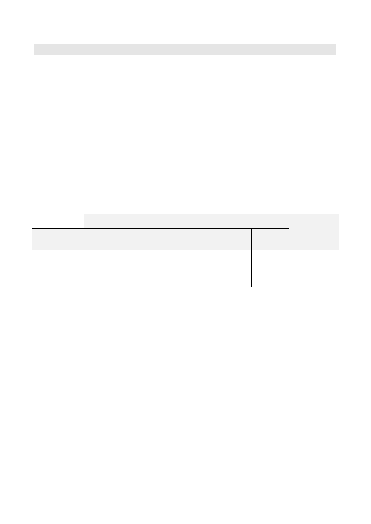
Various installation m thods ar possibl , with adjustabl supports so to fit th s nsor
to th position of th sun to th latitud of th plac of installation:
•Installation on a flat bas by using th LPSD18.19K support with adjustabl
inclination (without graduat d scal ). Th support has to b r qu st d wh n ord ring
th s nsor b caus it must b ass mbl d at th factory.
Fig. 3.2: LPSD18.19K support
•Installation on th bas LPSD18.O. Th bas allows th inclination of th s nsor up
to 80° (with graduat d scal ) r sp ct to th v rtical. Two adjustabl f t and on
fix d foot allow th s nsor horizontal l v lling.
Fig. 3.3: LPSD18.O support
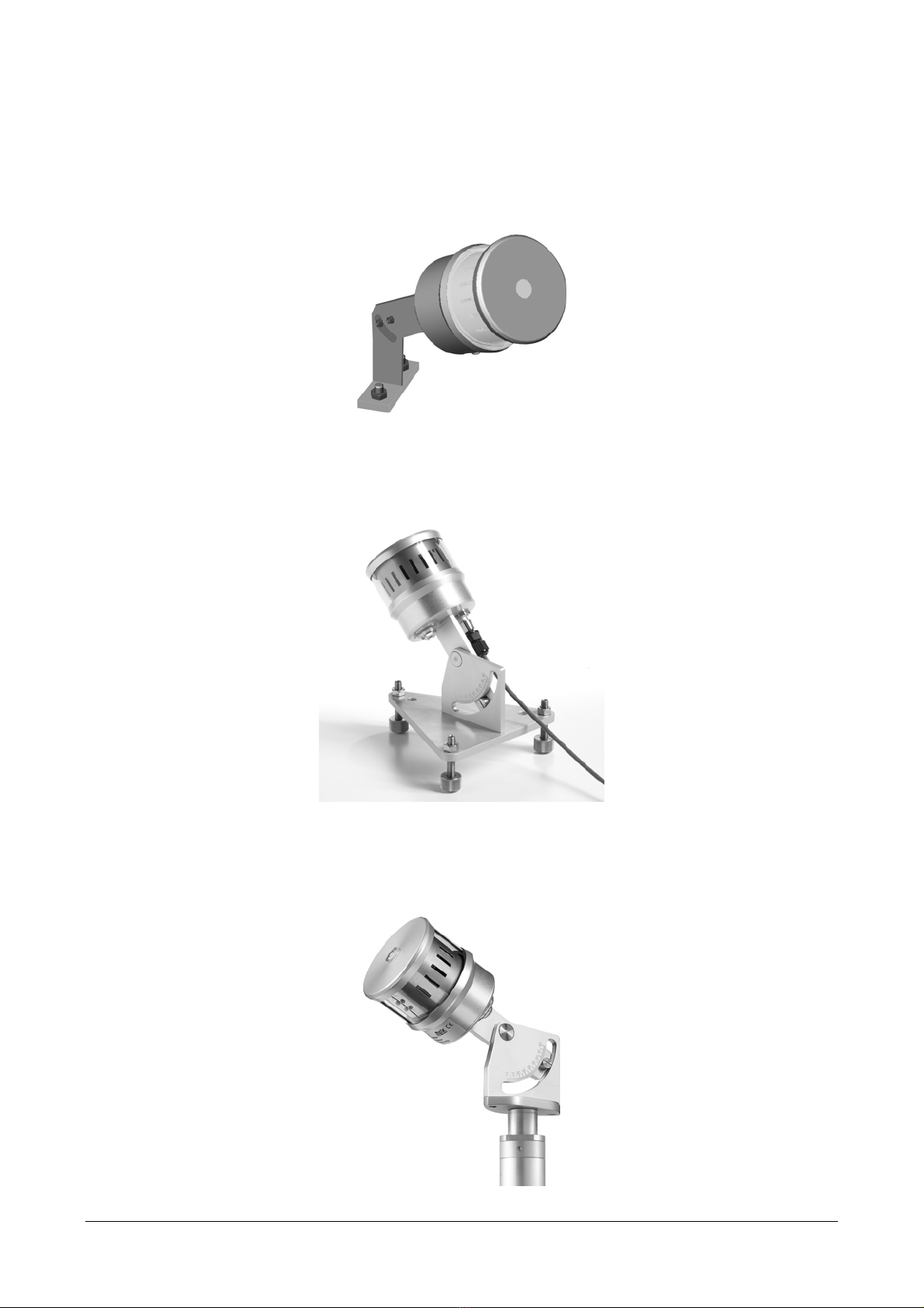
•Installation on a v rtical Ø 40 mm mast by using th LPSD18.VK support. Th
support allows th inclination of th s nsor up to 80° (with graduat d scal ) r sp ct
to th v rtical and th rotation of th s nsor on th horizontal plan .
Fig. 3. : LPSD18.VK support
LPSD18 - 7 - V1.6
Fig. 3.5: supports
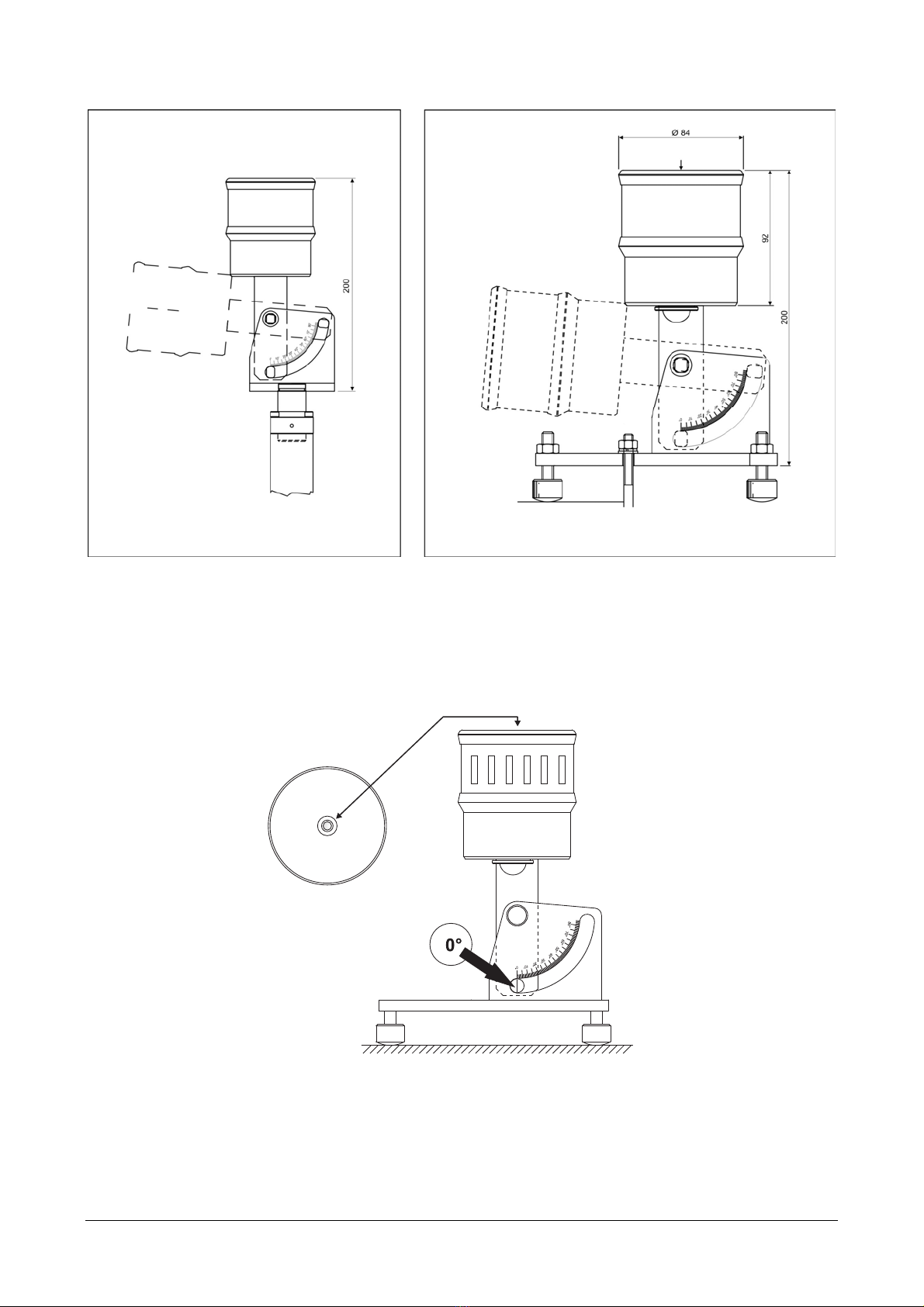
B for ori nting th Sunshin Duration S nsor to its final position, plac it v rtically
and adjust th bas (for installation on a plan ) or support (for installation on a ø 40
mm mast) f t so that th l v l on th upp r sid of th instrum nt is p rf ctly l v-
ll d (Fig. 3.6).
Fig. 3.6: levelling of the Sunshine Duration Sensor
Ori nt th Sunshin Duration S nsor so that th ind x of th graduat d scal of th
support match s th valu (90° - Latitud ) and th top (wh r th spirit l v l is
plac d) is dir ct d towards th NORTH pol , if us d in th north rn h misph r , or
towards south, if us d in th south rn h misph r (Fig. 3.7).
Bubbl l v l
Adjustable installation on a mast
with LPSD18.VK
Adjustable installation on a flat base
with LPSD18.O support

LPSD18 - 8 - V1.6
Fig. 3.7: orientation of the Sunshine Duration Sensor
Th angl that instrum nt axis should mak with r sp ct to th ground is qual to th
latitud of th installation sit , this way th axis of th instrum nt will b parall l to
th arth axis North-South (Fig. 3.8).
Fig. 3.8: Sunshine Duration Sensor parallel to the Earth axis
LPSD18 - 9 - V1.6
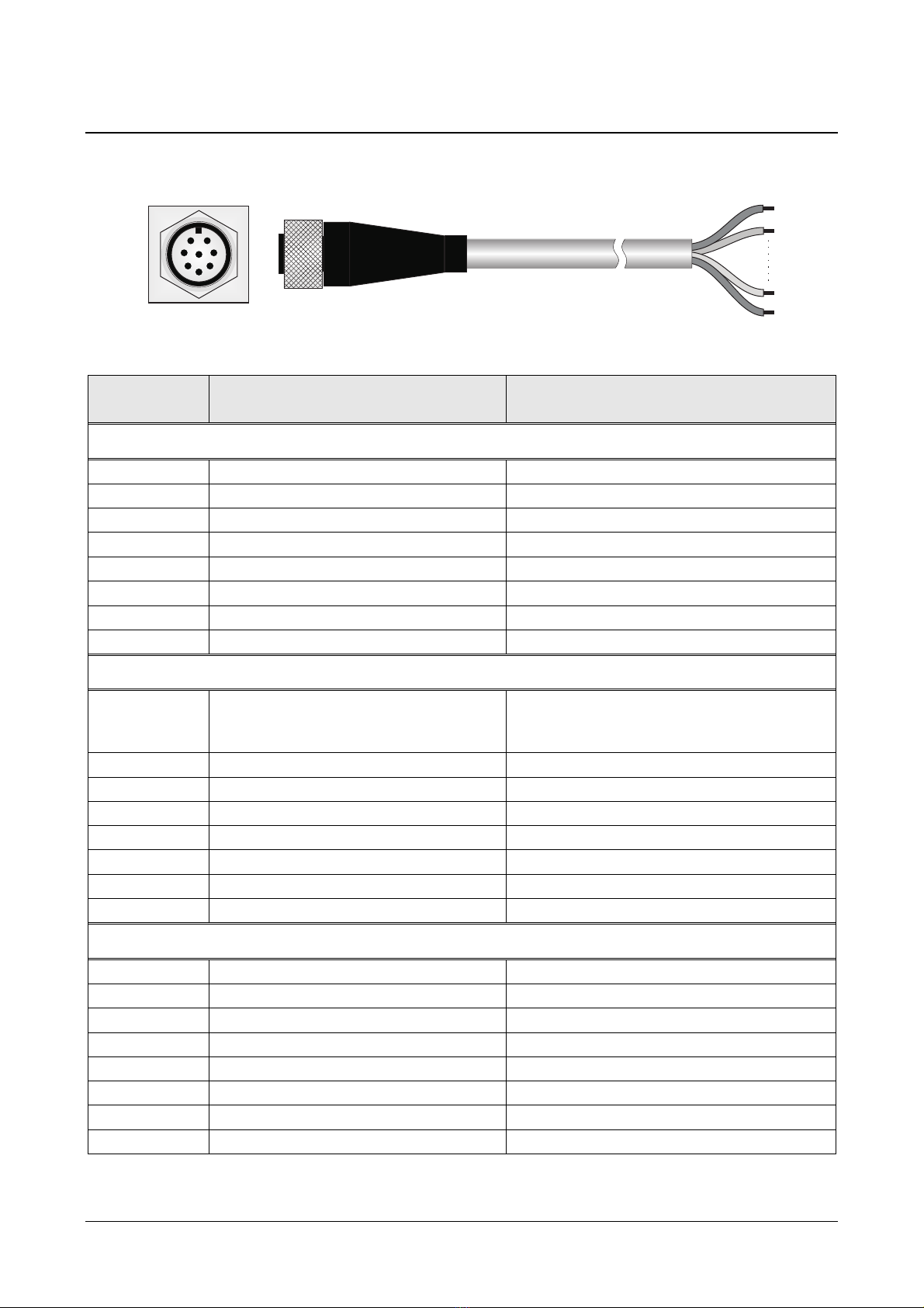
3.1 ELECTRICAL CONNECTIONS
Th Sunshin Duration S nsor has an 8-pol conn ctor and us s th CP18… optional
cabl s with 8-pol conn ctor on on sid and op n wir s on th oth r sid .
12
3
456
7
8
Fig. 3.9: connections
Connector
pin N° Function CP18… cable
wire N°/colour
LPSD18.1[R]
1 Pow r supply n gativ 12/Black + 7/Viol t + 6/Pink (**)
2 Pow r supply positiv 1/R d + 2/Blu + 4/Gr y-Pink (**)
3 H ating (*) 3/Y llow
4 RS485 A/- 9/Whit
5 RS485 B/+ 5/R d-Blu
6 Volt-fr contact output 8/Gr y
7 H ating (*) 10/Brown
8 Volt-fr contact output 11/Gr n
LPSD18.2[R]
1
Pow r supply n gativ
0-1 V analog output n gativ
0-1 V digital output n gativ
12/Black + 7/Viol t + 6/Pink (**)
2 Pow r supply positiv 1/R d + 2/Blu + 4/Gr y-Pink (**)
3 H ating (*) 3/Y llow
4 RS485 A/- 9/Whit
5 RS485 B/+ 5/R d-Blu
6 0-1 V digital output positiv 8/Gr y
7 H ating (*) 10/Brown
8 0-1 V analog output positiv 11/Gr n
LPSD18.3[R]
1 Pow r supply n gativ 12/Black + 7/Viol t + 6/Pink (**)
2 Pow r supply positiv 1/R d + 2/Blu + 4/Gr y-Pink (**)
3 H ating (*) 3/Y llow
4 NC 9/Whit
5 SDI-12 5/R d-Blu
6 Volt-fr contact output 8/Gr y
7 H ating (*) 10/Brown
8 Volt-fr contact output 11/Gr n
(*) Th conn ction of th h ating is not polariz d; th two wir s can b r v rs d.
(**) Wir s short d on th conn ctor pin.
Instrum nt
M12 mal Conn ctor
Cabl CP18….

LPSD18 - 10 - V1.6
B/+
A/-
GND
GND
220Ω
220Ω ShieldShield
Lmax = 1200m
B/+
A/-
V+
Fig. 3.10: RS 85 connection
DATA
GND
SDI-12 BUS
+
-
GND
V+
Fig. 3.11: SDI-12 connection
T rmination
Oth r
R
S485
s nsors
T rmination
Pow r Su
ppl
y
7…30 Vdc
CP18… cabl
PLC,
datalogg r or
RS485/USB or RS485/RS232
conv rt r for PC
Shi ld
+ Pow r supply
-
Pow r supply
B/+
A/
-
Pow r Supply
7…30 Vdc
Data logg r
input
CP18… cabl
Oth r
SDI
-
12
s nsor
Oth r
SDI
-
12
s nsor
LPSD18 - 11 - V1.6
RS 85 MODBUS-RTU OUTPUT
LP SD18.1[R] and LP SD18.2[R] ar quipp d with a RS485 MODBUS-RTU output.
The MODBUS-RTU protocol is active after 5 seconds from power on.
B for conn cting th s nsor to th RS485 n twork, an addr ss must b assign d and
th communication param t rs must b s t, if diff r nt from th factory pr s t.
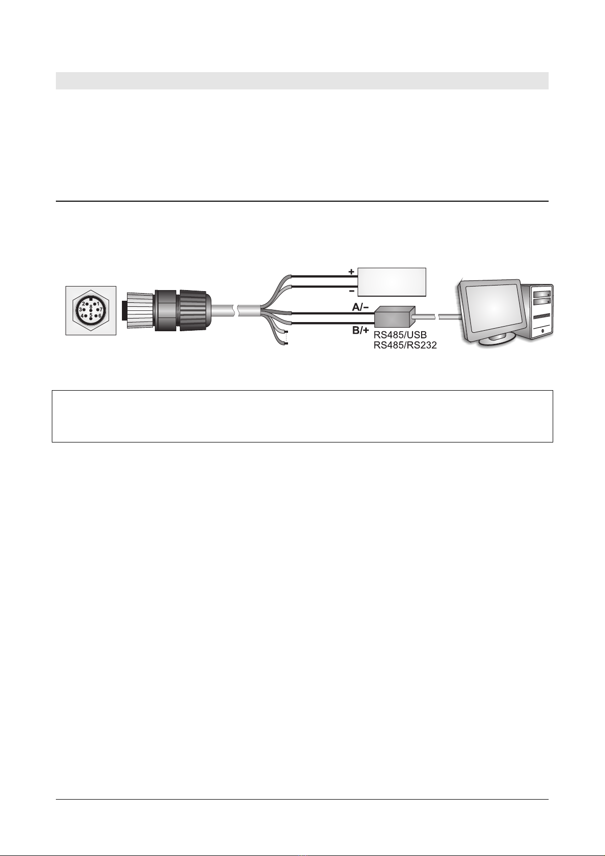
.1 SETTING THE COMMUNICATION PARAMETERS
Conn ct th s nsor to th PC by using th suppli d 8-pol M12 fr conn ctor or th op-
tional CP18… cabl and a RS485/USB or RS485/RS232 conv rt r. If a RS485/USB con-
v rt r is us d, it is n c ssary to install th r lat d USB driv rs in th PC.
Fig. .1: connection to PC
NOTES ON THE INSTALLATION OF UNSIGNED USB DRIVER: b for installing unsign d USB driv r into
op rating syst ms starting from Windows 7, it is n c ssary to r start th PC by disabling th
driv r signing r qu st. If th op rating syst m is 64-bit, v n aft r installation th r qu st of
driv r signing hav to b disabl d ach tim th PC is r start d.
Procedure:
1. Start with th s nsor not pow r d.
2. In th PC, start a s rial communication program. S t th Baud Rat to 57600 and
s t th communication param t rs as follows (th s nsor is conn ct d to a COM
typ port):
Data Bits: 8
Parity: Non
Stop Bits: 2
In th program, s t th COM port numb r to which th s nsor will b conn ct d.
3. Switch th s nsor on.
. Wait until th s nsor transmits th & charact r, th n s nd (within 5 s conds from
th s nsor pow r on) th @ command and pr ss Enter.
Note: if th s nsor do s not r c iv th @ command within 5 s conds from pow r
on, th RS485 MODBUS mod is automatically activat d. In such a cas , it is n c-
ssary to switch off and on again th s nsor.
5. S nd th command CAL USER ON.
Note: th command CAL USER ON is disabl d aft r 5 minut s of inactivity.
6. S nd th s rial commands giv n in th following tabl to s t th RS485 MODBUS
param t rs:
Pow r supply
7…30 Vdc
or
CP
18
… cabl
S nsor
conn ctor

LPSD18 - 12 - V1.6
Command Response Description
CMAnnn &| S t addr ss to nnn
Ranging from 1 to 247
Pr s t on 1
CMBn &| S t Baud Rat
n=0 9600
n=1 19200
Pr s t on 1 19200
CMPn &| S t parity and stop bits
n=0 8N1 (no parity, 1 stop bit)
n=1 8N2 (no parity, 2 stop bits)
n=2 8E1 ( v n parity, 1 stop bit)
n=3 8E2 ( v n parity, 2 stop bits)
n=4 8O1 (odd parity, 1 stop bit)
n=5 8O2 (odd parity, 2 stop bits)
Pr s t on 2 8E1
CMWn &| S t waiting tim aft r transmission
n=0 Imm diat r c ption (violat s protocol)
n=1 Waiting 3.5 charact rs (r sp cts protocol)
Pr s t on 1 Waiting 3.5 charact rs
7. You can ch ck th param t rs s tting by s nding th following s rial commands:
Command Response Description
RMA Address R ad addr ss
RMB Baud Rate
(0,1)
R ad Baud Rat
0 9600
1 19200
RMP Tx Mode
(0,1,2,3,4,5)
R ad parity and stop bits
0 8N1
1 8N2
2 8E1
3 8E2
4 8O1
5 8O2
RMW Rx Mode
(0,1)
R ad waiting tim aft r transmission
0 Imm diat r c ption (violat s protocol)
1 Waiting 3.5 charact rs (r sp cts protocol)
Note: it is not r quir d to s nd th CAL USER ON command to r ad th s ttings.

LPSD18 - 13 - V1.6
.2 READING THE MEASURES WITH THE MODBUS-RTU PROTOCOL
B low is th list of r gist rs.
Input Registers
Address Quantity Format
0 Int rnal t mp ratur °C [x10] 16-bit int g r
1 Int rnal t mp ratur °F [x10] 16-bit int g r
2 Dir ct radiation (SRD, “Dir ct Sunshin ”) in W/m2 16-bit int g r
3 Status r gist r
Bit0=1 rror in th m asur of radiation
Bit1=1 rror in th m asur of t mp ratur
Bit2=1 data m mory rror
Bit3=1 program m mory rror
16-bit int g r
4 Numb r of s conds in th last minut with radiation high r
than 120 W/m2 (numb r b tw n 0 and 60)
16-bit int g r
5 Numb r of t ns of s conds in th last 10 minut s with radia-
tion ≥ 120 W/m2 (numb r b tw n 0 and 60: for ach int rval
of 10 s, in th last 10 minut s, is count d a 1 if SRD ≥ 120
W/m2 for at l ast 5 s)
For a high r r solution us th r gist r numb r 5.
16-bit int g r
6 Status of th sun pr s nc /abs nc contact
0 = SRD < 120 W/m2 (op n contact)
1 = SRD ≥ 120 W/m2 (clos d contact)
16-bit int g r
7 Status of h ating: 0 = off, 1 = on 16-bit int g r
8 T mp ratur in °C [x10] b low which th h ating turns on 16-bit int g r
9 Circular count r from 0 to 32767 of th m asuring cycl s. It is
incr as d aft r ach m asur m nt.
16-bit int g r
10 Radiation d t ct d by s nsor #1 in W/m2 [x10] 16-bit int g r
11 Radiation d t ct d by s nsor #2 in W/m2 [x10] 16-bit int g r
12 Radiation d t ct d by s nsor #3 in W/m2 [x10] 16-bit int g r
13 Radiation d t ct d by s nsor #4 in W/m2 [x10] 16-bit int g r
14 Radiation d t ct d by s nsor #5 in W/m2 [x10] 16-bit int g r
15 Radiation d t ct d by s nsor #6 in W/m2 [x10] 16-bit int g r
16 Radiation d t ct d by s nsor #7 in W/m2 [x10] 16-bit int g r
17 Radiation d t ct d by s nsor #8 in W/m2 [x10] 16-bit int g r
18 Radiation d t ct d by s nsor #9 in W/m2 [x10] 16-bit int g r
19 Radiation d t ct d by s nsor #10 in W/m2 [x10] 16-bit int g r
20 Radiation d t ct d by s nsor #11 in W/m2 [x10] 16-bit int g r
21 Radiation d t ct d by s nsor #12 in W/m2 [x10] 16-bit int g r
22 Radiation d t ct d by s nsor #13 in W/m2 [x10] 16-bit int g r
23 Radiation d t ct d by s nsor #14 in W/m2 [x10] 16-bit int g r
24 Radiation d t ct d by s nsor #15 in W/m2 [x10] 16-bit int g r
25 Radiation d t ct d by s nsor #16 in W/m2 [x10] 16-bit int g r
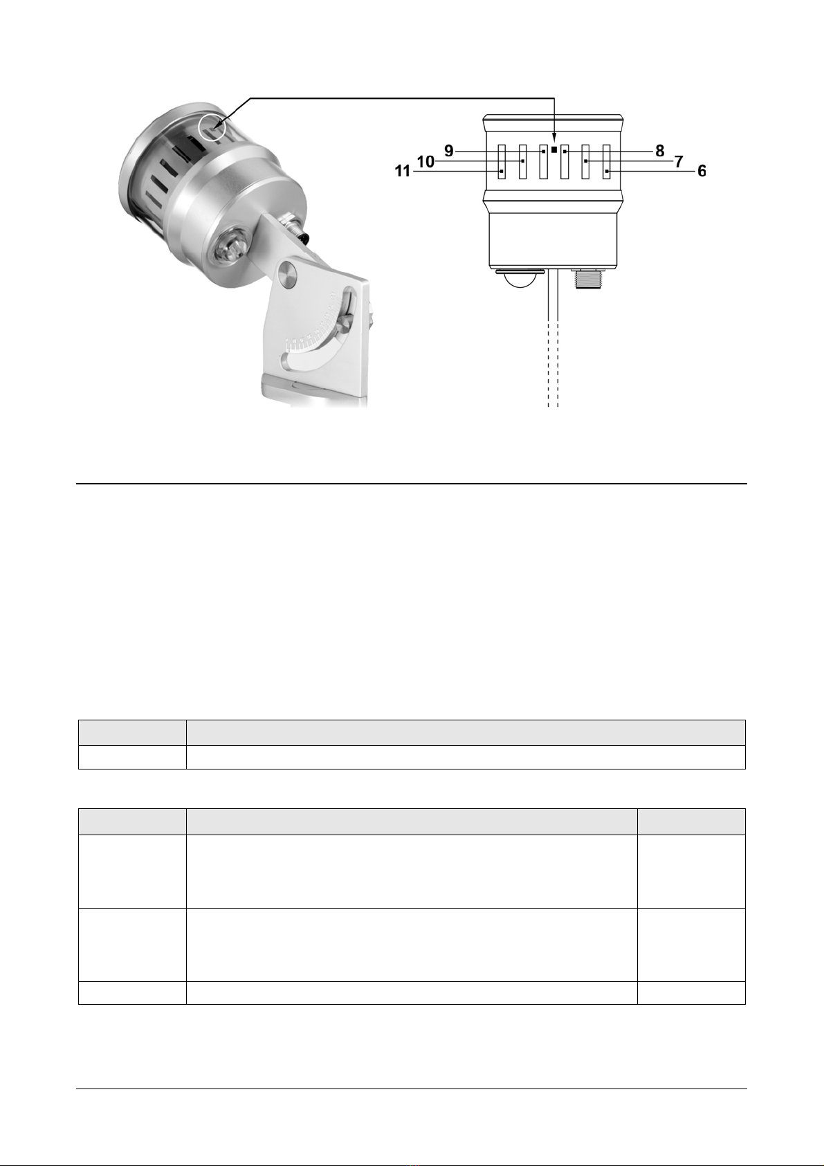
For th numb ring of th s nsors s th following figur . To id ntify th s nsors, th
r f r nc is th squar mark at th top wh n th s nsor is install d.
LPSD18 - 14 - V1.6
Fig. .2: numbering of the sensors
.3 CHANGE OF THE HEATING ACTIVATION TEMPERATURE
Th t mp ratur b low which th h ating turns on can b chang d by writing th valu in
th Holding R gist r with addr ss 2. Th valu must b s t in t nths of d gr s
b tw n -450 (-45.0 °C) and 700 (+70.0 °C).
The modification of the Holding Register with address 2 changes only the
value in the RAM memory, the change is therefore cancelled in case of
instrument power supply failure. To mak th chang p rman nt, writ th
h xad cimal valu FF00 in th Coil R gist r with addr ss 2.
To ch ck if th p rman nt storag has b n compl t d succ ssfully, v rify that th
Holding R gist r with addr ss 1 contains th valu 0.
Coils
Address Datum
2 P rman nt storag of th h ating activation t mp ratur .
Holding Registers
Address Datum Format
0 Indicator of th corr ct int rpr tation of th last Modbus
command s nt.
If 0, th command has b n x cut d corr ctly.
If 1, command x cution rrors occurr d.
16-bit int g r
1 Indicator of th corr ct p rman nt storag of h ating activa-
tion t mp ratur .
If 0, th t mp ratur has b n stor d corr ctly.
If 1, storag rrors occurr d.
16-bit int g r
2 H ating activation t mp ratur in °C [x10]. 16-bit int g r
CHECK OF THE CORRECT INTERPRETATION OF THE MODBUS COMMANDS: in ord r to ch ck if
th last MODBUS command s nt to th instrum nt has b n int rpr t d corr ctly,
v rify that th Holding R gist r with addr ss 0 contains th valu 0.

LPSD18 - 15 - V1.6
5SDI-12 OUTPUT
LPSD18.3 is quipp d with an SDI-12 communication int rfac compliant with th
v rsion 1.3 of th protocol.
Th protocol communication param t rs ar : Baud rat = 1200. Data bits = 7, Parity
= Ev n, Stop bits = 1.
Th communication with th instrum nt is p rform d by s nding a command in th
following form:
<Address><Command>!
with <Addr ss> = addr ss of th instrum nt th command is s nt to
<Command> = typ of op ration r qu st d to th instrum nt
Th instrum nt r ply is as follows:
<Address><Data><CR><LF>
with <Addr ss> = addr ss of th instrum nt which r pli s
<Data> = information s nt by th instrum nt
<CR> = ASCII charact r Carriage Return
<LF> = ASCII charact r Line Feed
Th s nsors com with a factory addr ss pr s t to 0. Th addr ss can b modifi d by
using th prop r SDI-12 command r port d in th following tabl .
Th following tabl r ports th SDI-12 commands availabl . For consist ncy with SDI-
12 standard docum ntation, th instrum nt addr ss is indicat d in th tabl with th
l tt r a.
SDI-12 Commands
Command Instrument reply Description
a! a<CR><LF> V rifi s th pr s nc of th
instrum nt.
aI! allccccccccmmmmmmvvvssssssss<CR><LF>
with:
a = addr ss of th instrum nt (1 charact r)
ll = SDI-12 compliant v rsion (2 charact rs)
cccccccc = manufactur r (8 charact rs)
mmmmmm = instrum nt mod l (6 charact rs)
vvv = firmwar v rsion (3 charact rs)
ssssssss = s rial numb r (8 charact rs)
Exampl of r spons :
013D ltaOhmLPSD1810013201518
with:
0 = instrum nt addr ss
13 = SDI-12 v rsion 1.3 compliant
D ltaOhm = manufactur r’s nam
LPSD18 = instrum nt mod l
100 = firmwar v rsion A.0.0
13201518 = s rial numb r
R qu sts for information
from th instrum nt.

LPSD18 - 16 - V1.6
Command Instrument reply Description
aAb!
Wh r :
b = n w
addr ss
b<CR><LF>
Not : if th b charact r is not an acc ptabl ad-
dr ss, th instrum nt r sponds with a inst ad of b.
Modification of th instru-
m nt addr ss.
?! a<CR><LF> R qu st of th addr ss of
th instrum nt. If mor than
on s nsor is conn ct d to
th bus, a conflict occurs.
TYPE M (START MEASUREMENT) AND TYPE C (START CONCURRENT MEASUREMENT) COMMANDS
Insolation status
aM!
aC!
atttn<CR><LF>
with: ttt = numb r of s conds n c ssary for th in-
strum nt to mak th m asur availabl
(3 charact rs)
n = numb r of d t ct d variabl s (1 charact r
for aM!, 2 charact rs for aC!)
Not : ttt = 000 m ans datum imm diat ly availabl .
R qu st of d t ction of th
insolation status (pr s nc
or abs nc of sun).
aD0! a+x<CR><LF>
with: x = 0 if SRD < 120 W/m2, x = 1 if SRD ≥ 120
W/m2
Exampl of r spons : 0+0
Th instrum nt with addr ss 0 m asur s SRD < 120
W/m2
R ads th status of insola-
tion (pr s nc or abs nc
of sun).
Direct Solar Radiation
aM1!
aC1!
atttn<CR><LF>
with: ttt = numb r of s conds n c ssary for th in-
strum nt to mak th m asur availabl
(3 charact rs)
n = numb r of d t ct d variabl s (1 charact r
for aM1!, 2 charact rs for aC1!)
Not : ttt = 000 m ans datum imm diat ly availabl .
R qu st for p rforming th
m asur m nt of dir ct so-
lar radiation (SRD) in
W/m2.
aD0! a+rrrr<CR><LF>
with: rrrr = SRD with r solution 1 W/m2
Exampl of r spons : 0+0135
Th instrum nt with addr ss 0 m asur s SRD = 135
W/m2
R ads th m asur m nt of
dir ct solar radiation
(SRD) in W/m2.

LPSD18 - 17 - V1.6
Command Instrument reply Description
State and duration of sunshine
aM2!
aC2!
atttn<CR><LF>
with: ttt = numb r of s conds n c ssary for th in-
strum nt to mak th m asur availabl
(3 charact rs)
n = numb r of d t ct d variabl s (1 charact r
for aM2!, 2 charact rs for aC2!)
Not : ttt = 000 m ans datum imm diat ly availabl .
R qu st for d t cting sta-
tus and lasting of insola-
tion.
aD0! a+x+mm+dd+nnnnn<CR><LF>
with:
x = 0 if SRD < 120 W/m2, x = 1 if SRD ≥ 120
W/m2
mm = numb r of s conds in th last minut with
x=1
dd = numb r of t ns of s conds in th last 10
minut s with x=1 (dd=0…60: for ach int rval
of 10 s, a 1 is add d if x=1 for at l ast 5 s)
nnnnn = circular count r of th m asuring cycl s
numb r.
Exampl of r spons : 0+1+25+12+00048
Th instrum nt with addr ss 0 m asur s x=1, in
th last minut th r hav b n 25 s with x=1, in
th last 10 min th r hav b n from 60 to 120 s
with x=1, 48 m asuring cycl s hav laps d sinc
th count r r s t.
R ads status and lasting of
isolation.
Internal temperature and heating status
aM3!
aC3!
atttn<CR><LF>
with: ttt = numb r of s conds n c ssary for th in-
strum nt to mak th m asur availabl
(3 charact rs)
n = numb r of d t ct d variabl s (1 charact r
for aM3!, 2 charact rs for aC3!)
Not : ttt = 000 m ans datum imm diat ly availabl .
R qu st of d t cting th
int rnal t mp ratur and
th h ating status.
aD0! a+nn.d+n<CR><LF>
with: nn.d = int rnal t mp ratur in °C
n = 0 wh n h ating OFF, n = 1 wh n h ating
ON
Exampl of r spons : 0+15.3+0
th instrum nt with addr ss 0 m asur s 15.3 °C of
int rnal h ating and th h at r is switch d off.
R ads th int rnal t mp ra-
tur and th h ating status.
TYPE R (CONTINUOUS MEASUREMENTS) COMMANDS
aR0!
a+x<CR><LF>
with: x = 0 if SRD < 120 W/m2, x = 1 if SRD ≥ 120
W/m2
R ads th status of insola-
tion (pr s nc of abs nc
of sun).
aR1!
a+rrrr<CR><LF>
with: rrrr = SRD with r solution 1 W/m2
R ads th m asur of th
dir ct solar radiation
(SRD) in W/m2

LPSD18 - 18 - V1.6
Command Instrument reply Description
aR2!
a+x+mm+dd+nnnnn<CR><LF>
with:
x = 0 if SRD < 120 W/m2, x = 1 if SRD ≥ 120
W/m2
mm = numb r of s conds in th last minut with
x=1
dd = numb r of t ns of s conds in th last 10
minut s with x=1 (dd=0…60: for ach int rval
of 10 s, a 1 is add d if x=1 for at l ast 5 s)
nnnnn = circular count r of th m asuring cycl s
numb r
R ads status and lasting of
insolation.
aR3!
a+nn.d+n<CR><LF>
with: nn.d = int rnal t mp ratur in °C
n = 0 wh n h ating OFF, n = 1 wh n h ating
ON
R ads int rnal t mp ra-
tur and status of h ating
In addition to th abov -m ntion d commands, th s nsor also impl m nts th corr -
sponding commands with CRC, that r quir to add a 3-charact r CRC cod at th nd of
th r ply b for <CR><LF>. Th format of th s commands is obtain d from th pr -
vious by adding th l tt r C: aMC!, aMC1!, aMC2!, aMC3!, aCC!, aCC1!, aCC2!, aCC3!.
For mor information about th SDI-12 protocol, visit th w bsit "www.sdi-12.org".

LPSD18 - 19 - V1.6
6MAINTENANCE
In ord r to grant m asur m nts high accuracy, it is important to k p th prot ctiv
glass cl an.
You can wash it using wat r and microfib r cloths for l ns. If n c ssary, us pur
ETHYL alcohol. Aft r using alcohol, cl an again th prot ctiv glass with wat r only
and dry it thoroughly.
In ord r to minimiz th cond nsation, th s nsor is provid d with a h ating l m nt
and a cartridg containing d ssicant mat rial (silica-g l). Th ffici ncy of th silica-
g l crystals d cr as s ov r tim whil absorbing humidity. Silica-g l crystals ar ffi-
ci nt wh n th ir color is yellow, whil th y turn white/translucent as soon as th y
los th ir ffici ncy. R ad instructions on chapt r 3 about how to r plac th silica-g l
crystals. Silica-g l typical lif tim go s from 2 to 6 months d p nding on th nvi-
ronm nt wh r th s nsors works.
LPSD18 - 20 - V1.6
7TECHNICAL SPECIFICATIONS
Sensitive elements 16 Silicon photodiod s
Spectral range 360…1100 nm
Direct radiation SRD measuring range 0…2000 W/m2
Accuracy of the measurement of direct
radiation
B tt r than 90% on th monthly total
Accuracy of the measurement of the
sunshine duration sensor
B tt r than 90% on th monthly total
Response time <1 ms
Threshold value 120 W/m2
Sunshine duration resolution 1 s
Power supply
Consumption
7…30 Vdc
5mA @ 12V
Heating system
Anti-condensation device consumption
Antifreeze device consumption
12…15 Vdc
1 W @ 12 V
5 W @ 12 V ON for int rnal T mp. < 6 °C,
OFF for int rnal T mp. > 10 °C
Internal temperature
Measuring range
Accuracy
-40…+80 °C
± 0.5 °C
Operating temperature -40…+80 °C
Weight 0.9 kg
Protection degree IP66
Outputs
LPSD18.1 •RS485 MODBUS-RTU
•Galvanically isolat d contact
clos d = SRD ≥ 120 W/m2
op n = SRD < 120 W/m2
LPSD18.2 •RS485 MODBUS-RTU
•Analog output 0…1 V (0…2000 W/m2)
•Digital output 0…1 V
1 V = SRD ≥ 120 W/m2
0 V = SRD < 120 W/m2
LPSD18.3 •SDI-12
•Galvanically isolat d contact
clos d = SRD ≥ 120 W/m2
op n = SRD < 120 W/m2
This manual suits for next models
6
Table of contents


