Delta OHM HD37AB1347 User manual

The quality level of our instruments is the result of the continuous development of the
product. This may produce some differences between the information written in this
manual and the instrument you have purchased. We cannot completely exclude errors in
the manual, for which we apologize.
The data, images and descriptions included in this manual cannot be legally asserted. We
reserve the right to make changes and corrections with no prior notice.
HD37AB1347
IAQ MONITOR
ENGLISH
REV. 2.5
02/08/2011
- -
2

- -
3
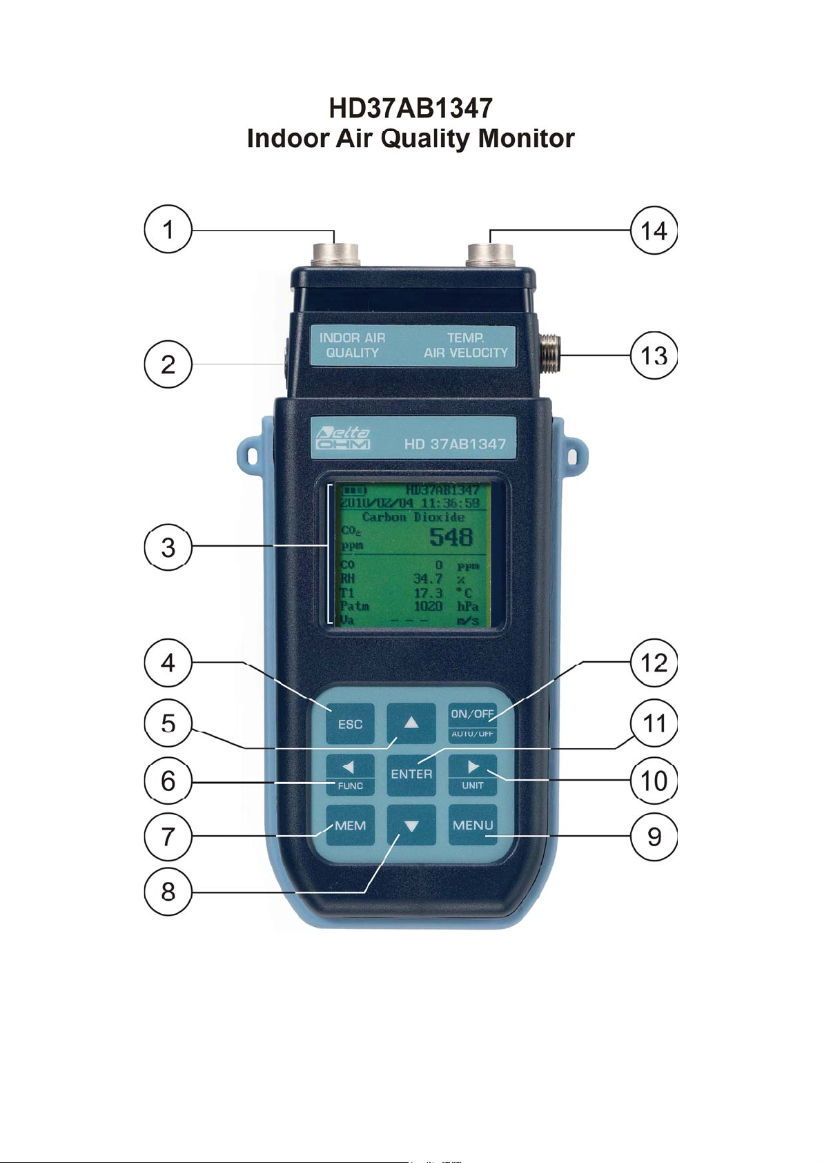
HD37AB1347
1. Indoor Air Quality input for the SICRAM probes:
•P37AB147: It measures CO2 Carbon Dioxide, CO Carbon Monoxide, Relative Humidity
RH, Temperature T, and Atmospheric Pressure Patm.
•P37B147: It measures CO Carbon Monoxide, Relative Humidity RH, Temperature T, and
Atmospheric Pressure Patm.
•Humidity and Temperature combined probes.
•Temperature probes with Pt100 sensor.
2. Power supply input.
3. Backlit graphic display.
4. ESC key: It allows to exit from the menu or, in case of a submenu, to exit from the current level
display.
5. Navigation key ▲: It allows navigation through the menus. During normal operation, it is used
to select the resetting of the statistical data and to scroll the displayed quantities upwards.
6. Navigation key ◄/Func: It allows navigation through the menus. In normal view, it allows to
display the statistical data: maximum, minimum, and average.
7. MEM key: It allows to start and end the recording of data (logging).
8. Navigation key ▼: It allows navigation through the menus. During normal operation, it is used
to cancel the resetting of the statistical data and to scroll the displayed quantities downwards.
9. MENU key: It allows to enter and exit the instrument’s functioning parameter setting menu.
10. Navigation key ►/ Unit: It allows navigation through the menus. During normal operation, it
changes the unit of measurement of the displayed main quantity.
11. ENTER key: In the menu, it confirms the data entered. In normal view, it allows to reset the
statistical data and to print them on the HD40.1 printer.
12. ON/OFF-Auto Off key: It turns the instrument on and off. When pressed together with the
ESC key, it disables the automatic turn off.
13. RS232 and USB serial port.
14. Temp-Air Velocity input (temperature and wind speed probes) for the SICRAM probes:
•Hot-Wire Sensor Wind Speed probes.
•Vane Wind Speed probes.
•Temperature probes with Pt100 sensor.

- -
4
TABLE OF CONTENTS
1. GENERAL CHARACTERISTICS............................................................................................................................ 6
2. THE USER INTERFACE........................................................................................................................................... 7
2.1 THE DISPLAY ................................................................................................................................................................ 7
2.2 THE KEYBOARD............................................................................................................................................................ 8
3. OPERATION ............................................................................................................................................................. 10
3.1.1 “►/UNIT” key for the unit of measurement................................................................................................. 11
3.1.2 Immediate printing of data............................................................................................................................ 12
3.1.3 The maximum, minimum and average values of the captured quantities...................................................... 12
3.1.4 Instrument Setup............................................................................................................................................ 13
3.1.5 Start of a new logging session....................................................................................................................... 13
4. MAIN MENU............................................................................................................................................................. 14
4.1 INFO MENU ................................................................................................................................................................. 14
4.2 LOGGING MENU.......................................................................................................................................................... 16
4.2.1 Log Interval................................................................................................................................................... 16
4.2.2 AutoPowerOff– AutoPowerOff Mode............................................................................................................ 17
4.2.3 Start/Stop Log – Automatic Start................................................................................................................... 18
4.2.4 Cancel Auto-Start.......................................................................................................................................... 20
4.2.5 Log File Manager ......................................................................................................................................... 21
4.3 SERIAL MENU (SERIAL COMMUNICATION) ................................................................................................................. 23
4.3.1 The Baud Rate ............................................................................................................................................... 24
4.3.2 Print Interval................................................................................................................................................. 24
4.4 SETTINGS .................................................................................................................................................................... 25
4.4.1 Contrast......................................................................................................................................................... 25
4.4.2 Backlight ....................................................................................................................................................... 26
4.4.3 Reset.............................................................................................................................................................. 26
4.5 AIR SPEED .................................................................................................................................................................. 27
4.5.1 Speed ............................................................................................................................................................. 27
4.5.2 Flow rate ....................................................................................................................................................... 28
4.5.3 Section........................................................................................................................................................... 28
4.6 VENTILATION RATE .................................................................................................................................................... 29
4.6.1 Definition of % Outdoor Air.......................................................................................................................... 29
4.6.2 Outdoor Air Calculation ............................................................................................................................... 30
4.7 PROBE CALIBRATION .................................................................................................................................................. 35
4.7.1 CO2Calibration ............................................................................................................................................ 36
4.7.2 CO Calibration – only P37AB147................................................................................................................ 37
4.7.3 RH calibration............................................................................................................................................... 41
4.8 LANGUAGE ................................................................................................................................................................. 43
5. SERIAL INTERFACE AND USB............................................................................................................................ 44
5.1 STORING AND TRANSFERRING DATA TO A PC ............................................................................................................ 46
5.1.1 Logging Function .......................................................................................................................................... 46
5.1.2 Clearing the memory..................................................................................................................................... 46
5.1.3 Print function ................................................................................................................................................ 46
6. CONNECTION TO A PC......................................................................................................................................... 47
6.1 CONNECTION TO THE RS232-C SERIAL PORT .............................................................................................................. 47
6.2 CONNECTION TO THE USB 2.0 PORT ........................................................................................................................... 47
6.3 REMOVING THE USB DRIVERS ................................................................................................................................... 51
7. INSTRUMENT SIGNALS AND FAULTS.............................................................................................................. 53
8. BATTERY SYMBOL – MAINS POWER SUPPLY .............................................................................................. 54
8.1 BATTERIES RECHARGING............................................................................................................................................ 54
8.2 NOTES FOR THE BATTERIES USE .................................................................................................................................. 55
8.3 REPLACEMENT OF THE BATTERY PACK ....................................................................................................................... 55

- -
5
8.4 BATTERIES DISPOSAL .................................................................................................................................................. 55
9. INSTRUMENT STORAGE...................................................................................................................................... 56
10. TECHNICAL CHARACTERISTICS ................................................................................................................... 57
10.1 TECHNICAL DATA OF THE PROBES THAT CAN BE CONNECTED TO THE INSTRUMENT .................................................. 59
10.1.1 P37AB147 and P37B147 SICRAM probes.................................................................................................. 59
10.1.2 Relative humidity and temperature combined probes using SICRAM module............................................ 60
10.1.3 Hot-Wire Wind Speed measurement probes with SICRAM module: AP471S1 – AP471S2 – AP471S3 –
AP471S4........................................................................................................................................................ 61
10.1.4 Vane Wind Speed measurement probes with SICRAM module: AP472S1 – AP472S2 – AP472S4 ............ 62
10.1.5 Temperature probes Pt100 using SICRAM module .................................................................................... 63
11. ORDERING CODES............................................................................................................................................... 64
11.1 CARBON DIOXIDE,CARBON MONOXIDE,RELATIVE HUMIDITY,TEMPERATURE,AND ATMOSPHERIC PRESSURE
PROBES WITH SICRAM MODULE ........................................................................................................................... 64
11.2 RELATIVE HUMIDITY AND TEMPERATURE PROBES USING SICRAM MODULE .......................................................... 64
11.3 HOT-WIRE WIND SPEED MEASUREMENT PROBES WITH SICRAM MODULE .............................................................. 64
11.4 VANE WIND SPEED MEASUREMENT PROBES WITH SICRAM MODULE...................................................................... 64
11.5 TEMPERATURE MEASUREMENT PROBES WITH SICRAM MODULE............................................................................. 65
11.6 ACCESSORIES............................................................................................................................................................ 65
11.6.1 Accessories for HD40.1 printer................................................................................................................... 65
11.6.2 Accessories for P37AB147 and P37B147 SICRAM probes ........................................................................ 65
11.6.3 Accessories for Wind Speed SICRAM probes.............................................................................................. 66
11.6.4 Accessories for Temperature-Humidity SICRAM probes............................................................................ 66

- -
6
1. GENERAL CHARACTERISTICS
The HD37AB1347 IAQ Monitor is an instrument manufactured by Delta Ohm for the analysis of
indoor air quality (IAQ, Indoor Air Quality).
The instrument simultaneously measures the following parameters, using the P37AB147 SICRAM
probe: CO2 Carbon Dioxide, CO Carbon Monoxide, Temperature, Relative Humidity, it
calculates Dew Point, Wet Bulb Temperature, Absolute Humidity, Mixing Ratio, Enthalpy and
Atmospheric Pressure. The P37B147 SICRAM probe does not measure CO Carbon Monoxide.
You can also connect Temperature and Humidity SICRAM combined probes, Hot-Wire Sensor
Wind Speed SICRAM probes, Vane Wind Speed SICRAM probes, and Temperature SICRAM
probes with Pt100 sensor, to the instrument.
The instrument, using a proper procedure, calculates the percentage of external air input (%
Outside Air) according to CO2Carbon Dioxide, temperature, and Ventilation Rate.
The HD37AB1347 is a datalogger with a memory capacity of 67600 recordings per each of the two
inputs, divided in 64 blocks. It uses the DeltaLog10 software, version 0.1.5.0.
Reference Standards: ASHRAE 62.1, Legislative Decree 81/2008. These regulations apply to all
confined spaces that could be used by people. Kitchens, baths, changing rooms and swimming
pools are included, due to their high humidity. You should take into account, in regard to air
quality, possible chemical, physical and biological contaminants, or the input of non sufficiently
purified external air (Ventilation Rate).
The instrument has a wide Dot Matrix graphic display with a resolution of 160x160 dots.
The instrument typical applications, using the above range of probes, are:
•Measurement of IAQ (Indoor Air Quality) and comfort conditions in schools, offices and
indoor spaces.
•Analysis and study of the Sick Building Syndrome, and of the resulting consequences.
•Checking the HVAC (Heating, Ventilation and Air Conditioning) system efficiency.
•Examination of IAQ conditions in factories to optimize microclimate and improve
productivity.
•Building Automation checks.
- -
7
2. THE USER INTERFACE
The user interface consist of a backlit LCD graphic display, and the power-on and setting keys.
When battery powered, and not pressing any key, the backlight turns off after about 1 minute. To
turn it back on, press any key. When using an external power supply, the backlight is always on.
Turn the instrument on and off with the ON/OFF key. When you turn the instrument on, the logo
and model will be displayed for a few seconds, and then the main display.
The quantities detected by the instrument can be viewed with a larger character size, at the top of
the display. The parameter displayed with a larger character is called main quantity. In order to
select the parameter to be displayed as main quantity, use the ▲▼ keys. For some quantities, you
can select the unit of measurement; temperature can be displayed as °C or °F.
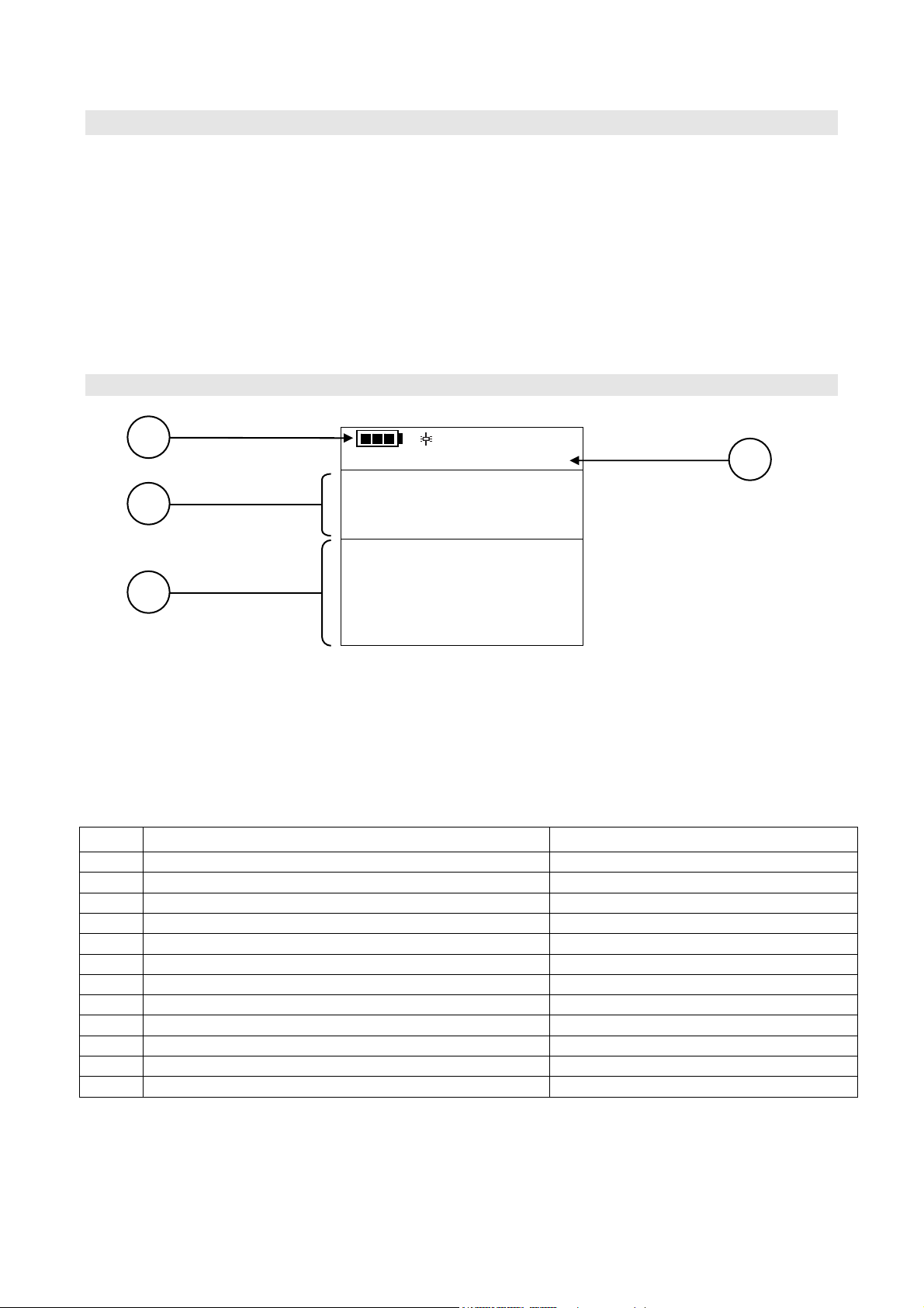
2.1 THE DISPLAY
HD37AB1347
2010/02/10 08:00:00
Carbon Dioxide
CO2
ppm 600
CO 0 ppm
RH 25.0 %
T1 17.0 °C
Patm 1000 hPa
Va 0.00 m/s
1. Battery’s charge status and instrument code. In case the logging function is on, this line
shows the current logging number and the time elapsed from logging start.
2. Main quantity (in this case, CO2Carbon Dioxide).
3. Display of all other quantities.
4. Current date and time.
The detected and computed quantities are:
CO2Carbon Dioxide ppm
CO Carbon Monoxide ppm
RH Relative Humidity %
T1 Temperature detected by the probe connected to input 1 °C – °F
Patm Atmospheric Pressure hPa
Va Wind Speed m/s – km/h – ft/min – mph – knot
FVa Flow Rate L/s – m3/h – m3/min – m3/h – ft3/s ft3/min
T2 Temperature detected by the probe connected to input 2 °C – °F
Td Dew Point °C – °F
Tw Wet Bulb Temperature °C – °F
AH Absolute Humidity g/m3
r Mixing Ratio g/kg
H Enthalpy kJ/kg
1
3
4
2
- -
8
2.2 THE KEYBOARD
The keys on the instrument perform the following functions:
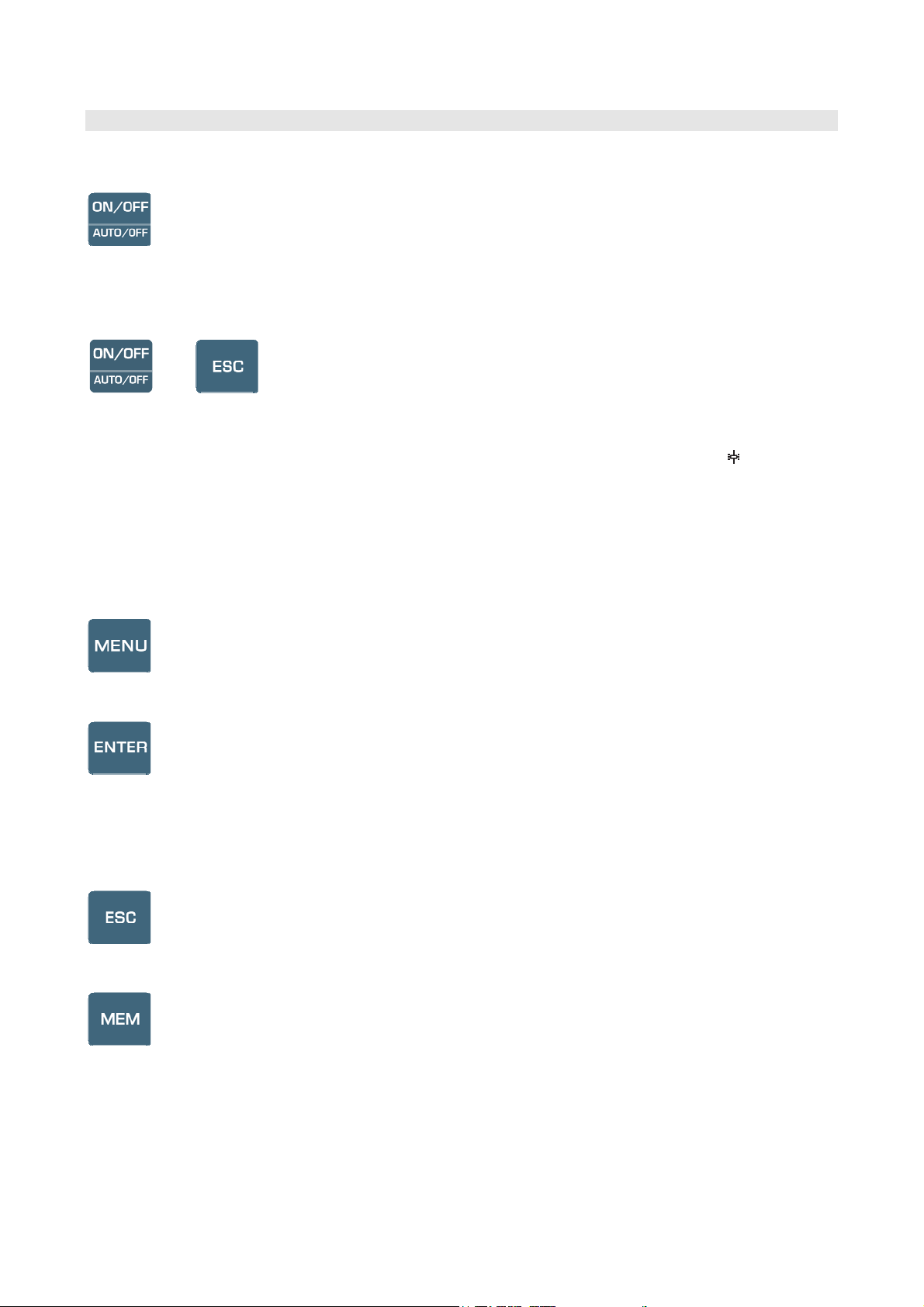
ON-OFF/AUTO-OFF key
It turns the instrument on and off.
When turning the instrument on, the first screen will be displayed. After few seconds the measured
quantities will be displayed.
+
Auto Power Off
The instrument has an AutoPowerOff function that automatically turns the instrument off after about
8 minutes if no key is pressed during the intervening time. The AutoPowerOff function can be
disabled by holding the ESC key pressed down when turning the instrument on: the symbol will
appear on the first line to remind the user that the instrument can only be turned off by pressing the
ON/OFF key.
The AutoPowerOff function is disabled when:
•External power is used.
•During data download.
•During logging.
MENU key
It allows to enter to and exit from the instrument’s functioning parameter setting menu.
ENTER key
In the menu, it confirms the entered data.
During normal operation:
•It confirms the resetting of the statistical data.
•It prints the current data on the HD40.1 printer.
ESC key
It allows to exit from the menu or, in case of a submenu, to exit from the current level display.
MEM key
It allows to start and end a “logging” session; the data sending interval must be set in the menu.

- -
9
Key ◄/FUNC
◄allows navigation through the menus.
FUNC: In normal view, it allows to select the statistical data: maximum, minimum, and average.
Key ▲
It allows navigation through the menus. During normal operation, it is used to select the resetting of
the statistical data and to scroll the displayed quantities.
Key ▼
It allows navigation through the menus. During normal operation, it is used to cancel the resetting
of the statistical data and to scroll the displayed quantities.
Key ►/UNIT
It allows navigation through the menus. During normal operation, it changes the unit of
measurement of the main quantity:
If the main quantity is Relative Humidity, by repeatedly pressing the UNIT key you can display
the following quantities:
RH Relative Humidity (%)
Td Dew Point (°C - °F)
AH Absolute Humidity (g/m3)
r Mixing Ratio (g/kg)
Tw Wet Bulb Temperature (°C - °F)
H Enthalpy (kJ/kg)
If the main quantity is Temperature, by repeatedly pressing the UNIT key you can display the
temperature in °C (Celsius degrees) or °F (Fahrenheit degrees).
If the main quantity is Wind Speed, by repeatedly pressing the UNIT key you can display the
Wind Speed in m/s – km/h – ft/min – mph – knot.
If the main quantity is Flow Rate, by repeatedly pressing the UNIT key you can display the Flow
Rate in L/s – m3/s – m3/min – m3/h – ft3/s – ft3/min.

- -
10
3. OPERATION
Before turning the instrument on, connect the SICRAM probes to the inputs: 8-pole male DIN
45326 connectors, located in the upper part of the instrument.
You can connect the following probes to the inputs:
Input 1 Indoor Air Quality for the SICRAM probes:
•P37AB147: It measures CO2 Carbon Dioxide, CO Carbon Monoxide, Relative Humidity
RH, Temperature T, and Atmospheric Pressure Patm.
•P37B147: It measures CO Carbon Monoxide, Relative Humidity RH, Temperature T, and
Atmospheric Pressure Patm.
•Humidity and Temperature combined probes.
•Temperature probes with Pt100 sensor.
Input 2 Temp-Air Velocity for the SICRAM probes:
•Hot-Wire Sensor Wind Speed probes.
•Vane Wind Speed probes.
•Temperature probes with Pt100 sensor.
NOTE:Connect the probes when the instrument is off. If a new probe is connected and the
instrument is on, it won’t be detected. You need to turn the instrument off and on.
NOTE:If you connect two temperature probes with Pt100 sensor to the two inputs, only the
Indoor Air Quality input probe will be detected. The Temp – Air Velocity input probe will be
ignored.
If a probe is disconnected when the instrument is on, you will get an acoustic signal (one beep per
second) and an indication on the display relevant to the physical quantity being disconnected. The
LOST message will be displayed.
During turning on, the following message is displayed for about 10 seconds:
Model HD37AB1347
Indoor Air Quality
Firm.Ver.=01.00
In addition to the Delta Ohm logo the instrument code and the firmware version are displayed.

- -
11
Connect the probes. Turn on the instrument: after about 10 seconds, the measurements will appear
on the display:
HD37AB1347
2010/02/10 08:00:00
Carbon Dioxide
CO2
ppm 600
CO 0 ppm
RH 25.0 %
T1 17.0 °C
Patm 1000 hPa
Va 0.00 m/s
CO2: Carbon Dioxide
CO: Carbon Monoxide
RH: Relative Humidity
T1: Temperature detected by the probe connected to input 1
Patm: Atmospheric Pressure
Va: Wind Speed
3.1.1 “►/UNIT” key for the unit of measurement
It allows navigation through the menus. During normal operation, it changes the unit of
measurement of the main quantity:
If the main quantity is Relative Humidity, by repeatedly pressing the UNIT key you can display
the following quantities:
RH Relative Humidity (%)
Td Dew Point (°C - °F)
AH Absolute Humidity (g/m3)
r Mixing Ratio (g/kg)
Tw Wet Bulb Temperature (°C - °F)
H Enthalpy (kJ/kg)
If the main quantity is Temperature, by repeatedly pressing the UNIT key you can display the
temperature in °C (Celsius degrees) or °F (Fahrenheit degrees).
If the main quantity is Wind Speed, by repeatedly pressing the UNIT key you can display the
Wind Speed in m/s – km/h – ft/min – mph – knot.
If the main quantity is Flow Rate, by repeatedly pressing the UNIT key you can display the Flow
Rate in L/s – m3/s – m3/min – m3/h – ft3/s – ft3/min.

- -
12
3.1.2 Immediate printing of data
By pressing Enter, you can print the current data on the HD40.1 printer.
Example of an immediate printout obtained using the HD40.1 printer
NOTES
========================
Model HD37AB1347 Instrument model
Indoor Air Quality
========================
Firm.Ver.=01.00
Instrument firmware version
Firm.Date=2010/01/15
Instrument firmware date
SN=12345678
Instrument serial number
User ID=0000000000000000 Identification Code
------------------------
Probe Ch.1 description Description of the probe connected to input 1
Type: CO2-C0 Fw.V0R0
Data cal.:2010/01/15
Serial N.:10010060
------------------------
Probe Ch.2 description Description of the probe connected to input 2
Type: Hot wire
Data cal.:2010/01/15
Serial N.: 10010100
========================
Date=2010/01/15 15:00:00 Date and time
CO2 850 ppm Carbon Dioxide
C0 0 ppm Carbon Monoxide
RH 29.2 % Relative Humidity
T1 22.7 °C Temperature detected at input 1
Patm 1010 hPa Atmospheric Pressure
Va 0.00 m/s Wind Speed
T2 22.0 °C Temperature detected at input 2
FVa 0.0 l/s Flow Rate
DP 3.8 °C Dew Point
AH 5.9 g/m3 Absolute Humidity
MR 5.0 g/kg Mixing Ratio
TW 12.8 °C Wet Bulb Temperature
H 35.5 kJ/kg Enthalpy
========================
3.1.3 The maximum, minimum and average values of the captured quantities
By pressing the ◄/FUNC key you can display the maximum, minimum and average values of the
measured quantities.
To reset the statistical data press the ◄/FUNC key until the “Reset? Yes No” message appears.
Select Yes using the ▲▼keys, and confirm with ENTER.
NOTE: Once selected, for example max, all displayed quantities indicate the maximum value. The
average is calculated on the first five minutes of samples, and then on the current average.

- -
13
3.1.4 Instrument Setup
In order to set the instrument, you have to open the main menu by pressing MENU. See chapter 4
for further details.
3.1.5 Start of a new logging session
Press MEM to start a Logging session: This key starts and stops the logging of a data block to be
saved in the instrument’s internal memory. The data logging frequency is set in the “Log
Frequency” menu parameter. The data logged between a start and subsequent stop represent a
measurement block.
When the logging function is on, the LOG indication and the logging session number are
displayed; a beep is issued each time a logging occurs.
To end the logging, press MEM again.
The instrument can turn off during logging between one capture and the next: The function is
controlled by the AutoPowerOff parameter. When the logging interval is less than 5 minutes, the
logging instrument remains on; with an interval of at least 5 minutes, it turns off between one
capture and the next.

- -
14
4. MAIN MENU
To access the programming menu press MENU:
MAIN MENU
1) Informations
2) Logging
3) Serial
4) Settings
5) Air speed
6) Air Changes
7) Probes Calibration
8) Language
If you do not press any key within 2 minutes, the instrument goes back to the main display.
Use the arrows ▲▼ and press ENTER to select an item.
To exit the selected item and return to the previous menu, press ESC.
To exit immediately from the main menu, press MENU again.
4.1 INFO MENU
Enter the main menu by pressing MENU. Using the ▲▼ arrows, select Informations and confirm
with ENTER.
INFORMATIONS
1) Info Instrument
2) Info Probes
3) Time / Date
▲▼ select
<ESC> exit/cancel
<ENTER> confirm
By selecting Info Instrument, the following information on the instrument will be displayed:
instrument code, firmware date and version, serial number, instrument calibration date,
identification code.
INFO INSTRUMENT
Model HD37AB1347
Firm.Ver.=01.00
Firm.Date=2010/02/10
Ser. Number=10010000
Calib: 2010/02/10
ID: 0000000000000000

- -
15
To change the ID, press ENTER. Use the ◄► arrows to select the item, and edit it with the ▲▼
arrows. Proceed with the other items, and finally confirm with ENTER.
By selecting Info Probes, the following information on the probes connected to the inputs will be
displayed: INFO PROBES
Input 1
Type= CO2-CO Fw.V0R0
Cal = 2010/02/10
SN = 10010000
Input 2
Type= Hot wire
Cal = 2010/02/10
SN = 10010001
INFO PROBES:
Description of the probe connected to input 1, Indoor Air Quality.
Calibration date of the probe connected to input 1, Indoor Air Quality.
Serial number of the probe connected to input 1, Indoor Air Quality.
Description of the probe connected to input 2, Temp – Air Velocity.
Calibration date of the probe connected to input 2, Temp – Air Velocity.
Serial number of the probe connected to input 2, Temp – Air Velocity.
Press ESC to return to the main menu. Press MENU to exit the menu.
Time/Date allows setting the date and time that will be shown at the top of the display.
To access the Time/Date submenu, proceed as follows:
1. Use the arrows ▲▼ to select Time/Date;
2. Press ENTER;
3. You will get the following message
TIME / DATE
year/mm/dd hh:mm
2010/02/10 08:00:00
set 00 seconds!
◄► select
▲▼ set
<ENTER> confirm
4. Use the arrows ◄► to select the data to be set (year/month/day and hour:minutes);
5. Once selected, the data will start blinking;
6. Use the arrows ▼▲ to enter the correct value;
7. Press ENTER to confirm and return to the main menu;
8. Or press ESC to return to the menu without making any change;
9. Press MENU to exit immediately from the main menu.
NOTE: In regard to the time, you can set hours and minutes. The seconds are always set to 00 (set
00 seconds!).

- -
16
4.2 LOGGING MENU
Enter the main menu by pressing MENU;
•Use the arrows ▲▼ to select Logging;
•Press ENTER: The parameter setting submenu for the logging sessions (to be captured) will
be displayed.
LOGGING MENU
1) Log frequency
2) Auto switch off
3) Start/Stop Log
4) Start Log Erase
5) Log File Manager
▲▼ select
<ENTER> confirm
4.2.1 Log Interval
Use this item to set the LOG interval (interval between two subsequent sample captures): To enter
this setting, proceed as follows:
Once you have accessed the LOGGING submenu (previous par.) use the arrows ▲▼ to select Log
frequency:
LOGGING MENU
LOG FREQUENCY
Insert interval
of memorization
h:mm:ss (1h max)
0:00:15
▲▼ set
<ENTER> confirm
1. Use the arrows ▲▼ to select the interval duration from a minimum of 15 seconds to a maximum
of one hour;
2. Press ENTER to confirm and return to the Logging menu;
3. Press ESC to return to the Logging menu without making any change;
4. Press ESC again to return to the main menu;
5. Press MENU to exit immediately from the menu.
These are the available values: 15 seconds - 30 seconds - 1 minute - 2 minutes - 5 minutes - 15
minutes - 20 minutes - 30 minutes - 1 hour
Logging
interval Storage capacity Logging
interval Storage capacity
15 seconds About 11 days and 17 hours 15 minutes About 1 year and 339 days
30 seconds About 23 days and 11 hours 20 minutes About 2 years and 208 days
1 minute About 46 days and 22 hours 30 minutes About 3 years and 313 days
2 minutes About 93 days and 21 hours 1 hour About 7 years and 261 days
5 minutes About 234 days and 17 hours

- -
17
4.2.2 AutoPowerOff– AutoPowerOff Mode
The Auto switch off item controls the instrument’s automatic turning off during logging, between
the capture of a sample and the next one. When the interval is lower than 5 minutes, the
instrument will always remain on. With intervals greater than or equal to 5 minutes, it is possible
to turn off the instrument between loggings: it will turn on one minute before sampling and will turn
off immediately afterwards, thus increasing the battery life.
Once you have accessed the LOGGING submenu (previous paragraph) use the arrows ▲▼ to
select Auto switch off. During configuration, the following is displayed:
•If the set Log Interval (see previous par.) is lower than 5 minutes, the following will be
displayed
LOGGING MENU
AUTO SWITCH OFF
Logging frequency
setted < 5 min.
During log session
the instrument
will shut ON
between two samples
<ESC> exit/cancel
If the set Log Interval (see previous par.) is greater or equal to 5 minutes, the following will be
displayed during configuration:
LOGGING MENU
AUTOPOWEROFF
Logging frequency
setted >= 5 min.
During log session
the instrument
will shut OFF
between two samples
▲▼ set
<ESC> exit/cancel
1. By using the arrows ▲▼ you can select:
ON (the instrument stays on)
OFF (the instrument stays off)
2. Press ESC to return to the Logging menu;
3. Press ESC again to return to the main menu;
4. Press MENU to exit immediately from the menu.

- -
18
4.2.3 Start/Stop Log – Automatic Start
The logging start and end can be programmed by entering the date and time.
Set the logging start date and time using the arrows. Confirm the logging start date and time using
ENTER. Then you are asked to set the data to end the recording. Set the logging end date and time
using the arrows. Confirm the logging end date and time using ENTER.
To enter this setting, proceed as follows.
Once you have accessed the LOGGING submenu (previous par.) use the arrows ▲▼ to select
Start/Stop Log: The following message will be displayed:
START/STOP LOG
Insert date START
def.=5m>Actual Date
2010/02/10 08:05:00
◄► select
▲▼ set
<ENTER> confirm
1. Use the arrows ◄► to select the data to be changed (year/month/day and
hour/minutes/seconds);
2. Once selected, the data will start blinking;
3. Use the arrows ▼▲ to change its value;
4. Confirm by pressing ENTER;
5. Press ESC to return to the Logging menu without making any change;
6. Press ESC again to return to the main menu;
7. Press MENU to exit immediately from the menu.
After setting the logging start time, the logging end time (Enter stop time) window will be
displayed:
START/STOP LOG
Insert END date
def.=10m>Start date
2010/02/10 08:10:00
Logging ends
at memory full
◄► select
▲▼ set
<ENTER> confirm
1. Use the arrows ◄► to select the data to be changed (year/month/day and
hour/minutes/seconds);
2. Once selected, the data will start blinking;
3. Use the arrows ▼▲ to change its value;
4. Confirm by pressing ENTER;
5. Press ESC to return to the Logging menu without making any change;
6. Press ESC again to return to the main menu;
7. Press MENU to exit immediately from the menu.

- -
19
8. Once both values have been set, a summary will be displayed showing the start and end time of
the LOG session.
LOGGING MENU
SETTED LOG
START Date
2010/02/10 10:29:00
END Date
2010/02/10 10:39:00
<ESC> exit/cancel
<ENTER> confirm
9. Press ENTER to confirm or ESC to exit without enabling the automatic start: In both cases, you
will return to the LOGGING menu.
10. Press MENU to exit immediately from the main menu.
When the instrument starts automatically a LOG session, a beep is issued on each capture and the
blinking LOG message is shown at the top of the display.
Press MEM to stop the session before the set time.
To cancel the automatic start setting, use the Start Log Erase function as illustrated in the
following paragraph.
NOTE: The automatic logging session is started even when the instrument is off. If it is off
when the automatic logging session is started, the instrument, even if powered by the mains, is
turned on few seconds earlier and remains on at the end of logging. If it is powered by the battery, it
is turned on and off at each data capture, except when the interval is lower than 5 minutes. At the
end of logging, it is turned off for good.
See paragraph 4.2.2 to set the automatic shut off.

- -
20
4.2.4 Cancel Auto-Start
Once the LOG session start and end times are set, you can inhibit the session automatic start by
using Start Log Erase.
Once you have accessed the LOGGING submenu:
1. Use the arrows ▲▼ to select Start Log Erase
2. The LOG session start and end times will be displayed:
MENU LOGGING
Auto-Start Erase
Setted start:
2010/02/10 10:29:00
Setted end:
2010/02/10 10:39:00
Press ▲▼ for
Auto-Start Erase
<ENTER> confirm
3. By pressing ▲the following message will be displayed:
LOGGING MENU
Auto-Start
not active
<ESC> exit/cancel
<ENTER> confirm
4. Press ENTER to cancel the automatic start;
5. Press ESC to exit without cancelling the automatic start;
6. Press ESC again to exit from the submenus;
7. Or press MENU to exit immediately from the main menu.
See the previous paragraph to set a new automatic start time after cancelling the previous one.
Table of contents
Other Delta OHM Monitor manuals


