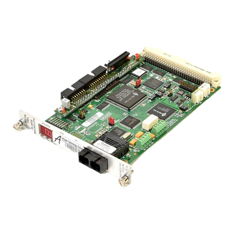
Delta Tau 3-4112 Series Quick user guide

Single Source Machine Control ……………………………………………..…...………………. Power // Flexibility // Ease of Use
21314 Lassen St. Chatsworth, CA 91311 // Tel. (818) 998-2095 Fax. (818) 998-7807 // www.deltatau.com
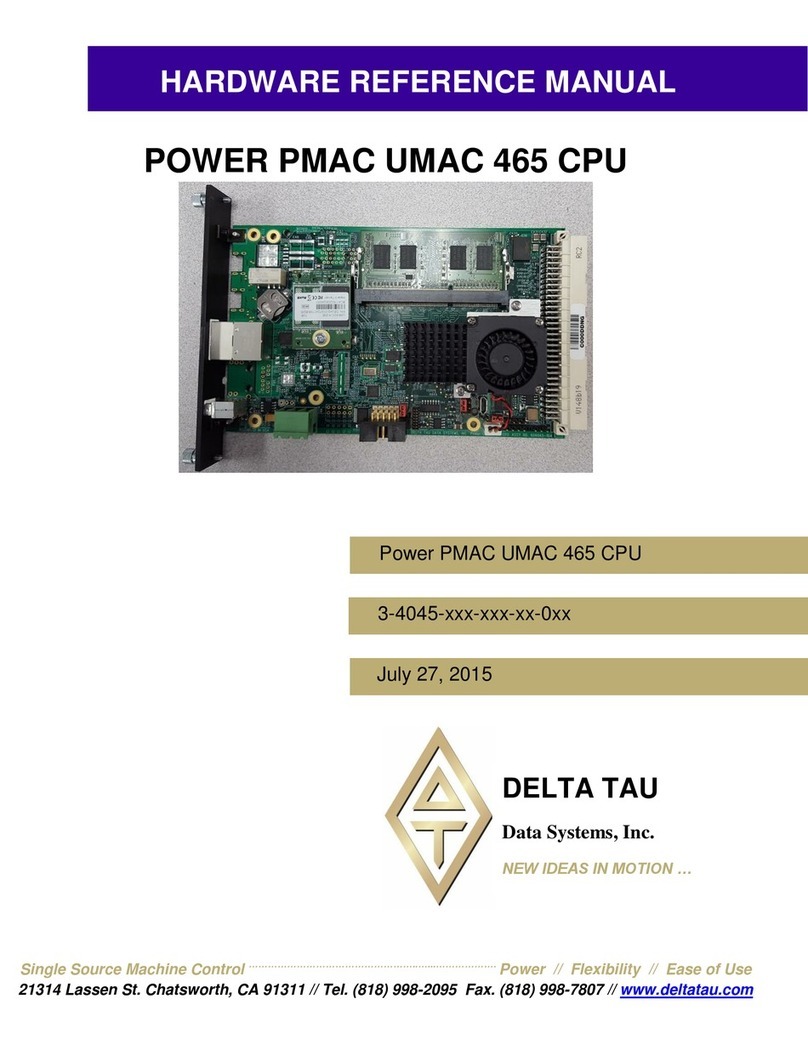
^1 HARDWARE REFERENCE MANUAL
^2POWER PMAC UMAC ARM CPU
^3Power PMAC UMAC ARM CPU
^4 3-4112-xxx-xxx-xx-0xx
^5June 22, 2018
DELTA TAU
Data Systems, Inc.
NEW IDEAS IN MOTION
…
DELTA TAU
Data Systems, Inc.
NEW IDEAS IN MOTION

Copyright Information
© 2018 Delta Tau Data Systems, Inc. All rights reserved.
This document is furnished for the customers of Delta Tau Data Systems, Inc.
Other uses are unauthorized without written permission of Delta Tau Data
Systems, Inc. Information contained in this manual may be updated from time-to-
time due to product improvements, etc., and may not conform in every respect to
former issues.
To report errors or inconsistencies, call or email:
Delta Tau Data Systems, Inc. Technical Support
Phone: (818) 717-5656
Fax: (818) 998-7807
Email: suppor[email protected]
Website: http://www.deltatau.com
Operating Conditions
All Delta Tau Data Systems, Inc. motion controller products, accessories, and
amplifiers contain static sensitive components that can be damaged by incorrect
handling. When installing or handling Delta Tau Data Systems, Inc. products,
avoid contact with highly insulated materials. Only qualified personnel should be
allowed to handle this equipment.
In the case of industrial applications, we expect our products to be protected from
hazardous or conductive materials and/or environments that could cause harm to
the controller by damaging components or causing electrical shorts. When our
products are used in an industrial environment, install them into an industrial
electrical cabinet or industrial PC to protect them from excessive or corrosive
moisture, abnormal ambient temperatures, and conductive materials. If Delta Tau
Data Systems, Inc. products are directly exposed to hazardous or conductive
materials and/or environments, we cannot guarantee their operation.

Safety Instructions
Qualified personnel must transport, assemble, install, and maintain this equipment. Properly
qualified personnel are persons who are familiar with the transport, assembly, installation, and
operation of equipment. The qualified personnel must know and observe the following standards
and regulations:
IEC364resp.CENELEC HD 384 or DIN VDE 0100
IEC report 664 or DIN VDE 0110
National regulations for safety and accident prevention or VBG 4
Incorrect handling of products can result in injury and damage to persons and machinery. Strictly
adhere to the installation instructions. Electrical safety is provided through a low-resistance earth
connection. It is vital to ensure that all system components are connected to earth ground.
This product contains components that are sensitive to static electricity and can be damaged by
incorrect handling. Avoid contact with high insulating materials (artificial fabrics, plastic film,
etc.). Place the product on a conductive surface. Discharge any possible static electricity build-
up by touching an unpainted, metal, grounded surface before touching the equipment.
Keep all covers and cabinet doors shut during operation. Be aware that during operation, the
product has electrically charged components and hot surfaces. Control and power cables can
carry a high voltage, even when the motor is not rotating. Never disconnect or connect the
product while the power source is energized to avoid electric arcing.
A Warning identifies hazards that could result in personal injury or
death. It precedes the discussion of interest.
Warning
Caution
A Caution identifies hazards that could result in equipment damage. It
precedes the discussion of interest.
Note
A Note identifies information critical to the understanding or use of
the equipment. It follows the discussion of interest.

REVISION HISTORY
REV.
DESCRIPTION
DATE
CHG
APPVD
1
Released
11/16/16
Sgm
Sgm
1
Revision
6/22/18
HB
Sgm

(This page intentionally left blank)

DELTA TAU POWER PMAC REFERENCE JUNE-2018
POWER PMAC UMAC ARM CPU BOARD HARDWARE REFERENCE 6
Table of Contents
Introduction..................................................................................................................................... 7
Configuration................................................................................................................................... 8
Optional Features ........................................................................................................................ 8
Hardware Setup............................................................................................................................. 10
E-Point Jumpers (Switch).......................................................................................................... 10
Connectors and Switches and Indicators....................................................................................... 11
Board Front/Back Side.............................................................................................................. 11
Backplane (UBUS) Connection ................................................................................................ 11
Ethernet Connections ................................................................................................................ 11
USB Connections...................................................................................................................... 12
Watchdog Timer Connection (TB2).......................................................................................... 18
Optional PCI Express Connection............................................................................................. 18
LED Indicators.......................................................................................................................... 18
Connector Pinouts ..................................................................................................................... 19

DELTA TAU POWER PMAC REFERENCE JUNE-2018
POWER PMAC UMAC ARM CPU BOARD HARDWARE REFERENCE 7
Introduction
The Power PMAC UMAC ARM CPU board (part number 604112-10x) provides a powerful
computing engine for UMAC (Universal Motion and Automation Controller) rack-mounted
systems. This 3U-format Eurocard (100 mm x 160 mm) can communicate with multiple
accessory boards over the UBUS backplane. These accessory boards provide interfaces to the
various machine elements for both motion and non-motion I/O, digital and analog.
The Power PMAC UMAC ARM CPU board can communicate with all accessory boards that the
older Turbo PMAC2 UMAC CPU board (603766-10x) could use. In addition, it can
communicate with a new generation of “PMAC3” UMAC accessory boards for motion, MACRO
ring, and I/O that employ a new generation ASIC and a 32-bit data bus on the backplane.
The Power PMAC UMAC ARM CPU board acts as both a dedicated controller and a general-
purpose embedded computer. It uses the Linux operating system with a hard-real-time kernel that
guarantees determinacy of tasks such as servo loop closure.

DELTA TAU POWER PMAC REFERENCE JUNE-2018
POWER PMAC UMAC ARM CPU BOARD HARDWARE REFERENCE 8
Configuration
The base version of the Power PMAC UMAC ARM CPU board provides a 1-slot 3U-format
(100mm x 160mm) Eurocard board with the following features:
1.0 GHz 32-bit Dual Core ARM CPU with built-in hardware floating-point math
capabilities
1 GByte DDR3L active memory with error correction
1 GByte built-in NAND flash memory for user application storage
1000-Base-T (1 Gbit/sec) Ethernet communications port
USB 3.0 Host port
RS-232 communications port
32-bit UBUS backplane port to UMAC accessory boards
Optional Features
The following features are optionally present on the Power PMAC UMAC ARM CPU board:
2 GByte DDR3L active memory
4G Byte built-in NAND flash memory for user application storage
PCI Express expansion port
Optional EtherCAT capability

DELTA TAU POWER PMAC REFERENCE JUNE-2018
POWER PMAC UMAC ARM CPU BOARD HARDWARE REFERENCE 9
PART NUMBER ORDERING INFORMATION
3 - 4 1 1 2 - A U - 0 - B 00
Power UMAC 2 CORE ARM CPU
A - Dual-Core 1GHz ARM CPU
Main Board CPU and Memory Options
A
C
** This Option May require additional plates
*** For EtherCAT option requires selection from
A - 1 GB RAM & 1 GB Flash
E - 2 GB RAM & 4 GB Flash
DA B
B
K L
00 - No Additional* Options
xx - Factory assigned digits
for Additional* Options
K L
Factory Assigned Options
D
2 - 2 RJ45 Ethernet Ports OR
(1 EtherNet & 1 EtherCAT Port***)
4 –PCIe** & 2 RJ45 Ethernet Ports OR
(1 EtherNet & 1 EtherCAT Port***)
E
PCIe, EtherNet And/Or
EtherCAT Options
0 - No EtherCAT
1 - EtherCAT I/O Only
2 - EtherCAT 4 Servo Axes and I/O
3 - EtherCAT 8 Servo Axes and I/O
5 - EtherCAT 16 Servo Axes and I/O
9 - EtherCAT 32 Servo Axes and I/O
For more then 32 Servo Axes call factory
EtherCAT Options
Requires EtherCAT Port Option From
E
U –UMAC Option with (30U-604147-10X)
C
Format Option
E
G
B0 –1 SLOT Black Front, Top and Bottom plates
G
Plate Option
F
E
E
H
H

DELTA TAU POWER PMAC REFERENCE JUNE-2018
POWER PMAC UMAC ARM CPU BOARD HARDWARE REFERENCE 10
Hardware Setup
There is virtually no hardware setup required before installation of the Power PMAC UMAC
ARM CPU board in the system.
E-Point Jumpers (Switch)
The E-point jumpers on the board have been replaced with a 4 pole switch. This is intended for
factory use only. Their functionality is listed here primarily for reference.
S1-1: For factory use only. Must remain off (open)
S1-2: Should remain off (open) for normal operation. On (closed) disables the watchdog timer
circuit.
S1-3: Enables PCIe connector when on (closed). To disable PCIe connector leave off (open)
S1-4: For factory use only. Must remain off (open)

DELTA TAU POWER PMAC REFERENCE JUNE-2018
POWER PMAC UMAC ARM CPU BOARD HARDWARE REFERENCE 11
Connectors and Switches and Indicators
Board Front/Back Side
Backplane (UBUS) Connection
To connect the Power PMAC UMAC ARM CPU board to the UBUS backplane, simply slide the
board into any slot of a UMAC that has a bus connection socket of a UBUS backplane board. It
does not matter which socket on the backplane board is used, although customarily the CPU
board is installed in the leftmost slot.
Getting the P1 backplane connector on the CPU board to mate firmly with the socket on the
backplane requires some force, but can easily be done by hand. In a standard UMAC rack, getting
the front plate flush with the front of the rack and turning the front screws firmly will ensure a
good connection with the backplane.
The Power PMAC UMAC ARM CPU board gets its electrical power through the UBUS
backplane board, whether the power comes from a Delta Tau power supply or an external user-
provided supply.
Ethernet Connections
The Power PMAC UMAC ARM CPU board is provided with two Ethernet TCP/IP
communication ports on the front panel: ETH 0 and ETH 1. ETH 1 may be used for the field bus
option EtherCAT provided the option has been purchased. All ports can accept standard CAT-5

DELTA TAU POWER PMAC REFERENCE JUNE-2018
POWER PMAC UMAC ARM CPU BOARD HARDWARE REFERENCE 12
Ethernet cables with RJ-45 connectors. All ports provide transformer isolation to prevent ground-
loop problems.
ETH 0 Ethernet Port (P11)
The “ETH 0” port is the top Ethernet connector on the front panel. It is the primary port for
communicating with the CPU board from a host computer, as when using the Integrated
Development Environment (IDE) program running on a WindowsTM PC for developing your
application.
Note that multiple computers on a single network can independently communicate to the Power
PMAC CPU board through this single hardware port.
ETH 2 Ethernet Port (P22)
The “ETH 2” port is immediately under the top Ethernet connector on the front panel. It is the
auxiliary Ethernet port and may be used as the EtherCAT port.
USB Connections
The Power PMAC UMAC ARM CPU board provides two USB ports one on the front panel as
the host port and one device port internal on the PCB.
Caution
Caution: USB ports are not electrically isolated, so care must be taken
in the grounding scheme when any separately powered device is
connected to one of these ports. Poor-quality communications and
even permanent component damage is possible when ground loop
issues or significant differences in ground potential exist.
USB Host Port (J20)
The USB “host” port is labeled “USB 1” on the front panel. It is a “Standard-A” USB 3.0 format
connector located just below the Ethernet ports and has a horizontal orientation. With this port,
the Power PMAC CPU acts as the host computer and various peripheral devices can be connected
through this port.
Probably the most common peripheral device used on this port is the “USB stick” flash drive. The
Power PMAC CPU board will automatically recognize standardly formatted flash drives
connected to this port. It is even possible to boot the CPU from this drive if the proper boot files
are present on the drive. It is also possible to use USB peripheral devices such as true disk drives
and keyboards.
USB Flash Memory and USB serial Port (P1 on 604147 daughter card)
The USB Flash Memory/Serial Port is labeled “P1” on the 604147 daughter card. It is a “Micro-
B” format connector. This port has dual functionality.
USB serial Port Functionality
When the initially plugged in the DIAG MODE LED is illuminated green,. This indicates that
the USB connection is serial. The baud rate for the connection is 115200, 8 data bits, no parity
and 1 stop bit. The COM port that is used by the PC is solely determined by Windows. Please

DELTA TAU POWER PMAC REFERENCE JUNE-2018
POWER PMAC UMAC ARM CPU BOARD HARDWARE REFERENCE 13
examine the Windows device manager to know what COM port Windows has chosen. The serial
mode is useful for diagnostics for use with a Windows serial console program such as putty.exe.
The PowerPMAC must be externally powered for data to be present from this port. Below is an
example of the startup diagnostic data that the CPU prints over the serial port on startup.
USB Flash Memory Functionality
To place Processor in USB Flash memory mode do the following
1.) Make sure power is NOT applied to the UMAC ARM CPU Board and plug a micro USB
cable from the PC to the side of the UMAC ARM CPU. There will be a green LED
indicating the UMAC ARM CPU is receiving power from the PC USB connector to
power its built in USB Serial port.
2.) Using a small screw driver click the switch S2 (see figure 2) internal to the UMAC ARM
CPU Board to change the USB Diag mode connection from USB Serial to USB mass
storage. The LED will switch from GREEN to ORANGE once you have successfully
switched the UMAC ARM CPU Board USB diagnostic mode to mass storage. In
addition simultaneously Windows will automatically open an explorer session for the
Power PMAC CPU mass storage disk.

DELTA TAU POWER PMAC REFERENCE JUNE-2018
POWER PMAC UMAC ARM CPU BOARD HARDWARE REFERENCE 14
The Power PMAC CPU’s USB port now acts as a flash memory stick providing internal directory
structure and file access from a Windows PC while the board is unpowered.
Figure 1. USB Connector is for serial port diagnostics.
Figure 2. USB Connector is for a mass storage device
When configuring the USB connection for mass storage three folders will be present, “etc”,
“ppmac”and “etherlab”. The “ppmac”folder represents the Power UMAC Firmware binary
applications and should not be modified. The “etherlab”folder contains the EtherCAT
configuration and should not be modified. The “etc”folder contains the network settings. The
file interfaces maybe inspected to determine the current configured network setting of the Power
PMAC. WARNING editing the interfaces file with notepad will prevent the network setting from
working.

DELTA TAU POWER PMAC REFERENCE JUNE-2018
POWER PMAC UMAC ARM CPU BOARD HARDWARE REFERENCE 15
Restore Original Factory Image using CK3e2_4_1_2Update.zip
The Power PMAC CPU maybe restored to its factory image state using the
CK3e2_4_1_2Update.zip package available through forums.deltatau.com in the File Depot
section under Power PMAC –Firmware –Release –2.4.1.2 when in USB Flash Memory mode
Launch the program PPMACDiskImage.exe extracted from Ck3e2_4_1_2Update.zip from a
Windows PC and select CK3E for the Target Type. Click Restore Disk Image button and use the
Open Image File Dialog and browse for the ck3e2_4_1_2update.vhd image file. Then select
Restore Disk Image

DELTA TAU POWER PMAC REFERENCE JUNE-2018
POWER PMAC UMAC ARM CPU BOARD HARDWARE REFERENCE 16
There will be a progress bar indicating completion of the imaging process followed by a complete
message.

DELTA TAU POWER PMAC REFERENCE JUNE-2018
POWER PMAC UMAC ARM CPU BOARD HARDWARE REFERENCE 17
As new images updates are made available this same method may be used to upgrade firmware.
In addition, using the create disk image button a user may take a complete backup of the CPU
state for restoration.

DELTA TAU POWER PMAC REFERENCE JUNE-2018
POWER PMAC UMAC ARM CPU BOARD HARDWARE REFERENCE 18
Watchdog Timer Connection (TB2)
The Power PMAC UMAC ARM CPU board provides a dedicated connector for the output of the
on-board watchdog timer. This 3-point removable terminal block is on the bottom edge of the
board, midway. The solid-state relay output on this connector can be used for fail-safe shutdown
of power circuitry in case of timer trip or loss of controller power.
Optional PCI Express Connection
The Power PMAC UMAC ARM CPU board optionally provides one PCI Express connector on
the “back side” of the board (the left side when looking at the rack from the front). This permits
the installation of PCI Express expansion cards inside the rack provided there is space available
in the rack to the left of the CPU board, such as video cards, vision systems, and additional
Ethernet ports in the Power PMAC system.
PCIe (x4) Connector (P4)
The P18 connector near the top of the back side of the CPU board provides a “times 4” (x4 – four
serial channels) PCI Express connection. It is considered Port 1/Slot 1 by the CPU. PCI Express
“x1” and “x4” accessories can be installed in this connector. This connector is in the right-angle
configuration. The PCIe accessory board will be parallel to the CPU board, and the assembly will
occupy 2 or 3 slots in the UMAC rack.
LED Indicators
D10: This is a dual colored LED. When this LED is green, it indicates that power is applied to the
+5V input when this LED is red, it indicates that the watchdog timer has tripped.
D15: This is an amber colored LED. When this LED is lit it indicates that the backplane reset has
completed and Power PMAC is ready for communication.
D33: This is a dual colored LED. When this LED is green, it indicates that the “P1” port on the
604147 daughter card is in RS-232 mode. When this LED is yellow it indicates that the “P1” port
on the 604147 daughter card is in USB-Flash mode. This is toggled by the micro push button
switch “S2”.

DELTA TAU POWER PMAC REFERENCE JUNE-2018
POWER PMAC UMAC ARM CPU BOARD HARDWARE REFERENCE 19
Connector Pinouts
P1 UBUS32 Backplane Connector Pinout
Pin #
Row A
Row B
Row C
1
+5V
+5V
+5V
2
GND
GND
GND
3
BD09 (BD01)
BD00 (rsvrd.)
BD08 (BD00)
4
BD11 (BD03)
BD01 (rsvrd.)
BD10 (BD02)
5
BD13 (BD05)
BD02 (rsvrd.)
BD12 (BD04)
6
BD15 (BD07)
BD03 (rsvrd.)
BD14 (BD06)
7
BD17 (BD09)
BD04 (rsvrd.)
BD16 (BD08)
8
BD19 (BD11)
BD05 (rsvrd.)
BD18 (BD10)
9
BD21 (BD13)
BD06 (rsvrd.)
BD20 (BD12)
10
BD23 (BD15)
BD07 (rsvrd.)
BD22 (BD14)
11
BD25 (BD17)
rsrvd
BD24 (BD16)
12
BD27 (BD19)
rsrvd
BD26 (BD18)
13
BD29 (BD21)
rsrvd
BD28 (BD20)
14
BD31 (BD23)
BCSDIR(rsvrd.)
BD30 (BD22)
15
rsrvd
BCS0-(rsvrd.)*
rsrvd
16
BA01
BCS1-(rsvrd.)*
BA00
17
BA04 (BA03)
BCS5-(rsvrd.)*
BA02
18
BA03 (BX/Y)
BA15 (BA14)
BA05 (BA04)
19
BCS3-
BA07 (BA06)
BCS2-
20
BA06 (BA05)
BA08 (BA07)
BCS4-
21
BCS12-
BA09 (BA08)
BCS10-
22
BCS16-
BA10 (BA09)
BCS14-
23
BA14 (BA13)
BA11 (BA10)
BA13 (BA12)
24
BRD-
BA12 (BA11)
BWR-
25
rsrvd
DPRCS1-
rsrvd
26
WAIT-
VMECS1-
BRESET
27
PHASE+
UMAC_INT-
SERVO+
28
PHASE-
INT1- (EQU1-)
SERVO-
29
AGND
INT2- (EQU2-)
AGND
30
A-15V
PWM_ENA
A+15V
31
GND
GND
GND
32
+5V
+5V
+5V
Notes:
1. These signals are provided primarily for reference, as this is typically an “internal”
connector inside the system without direct user access.
2. Names in italics refer to the naming of this pin for the older UBUS24 24-bit backplane.
Accessory boards designed for the Turbo PMAC UMAC CPU use these signal
designations.
3. “rsvrd” means “reserved for future use”
4. “B” as the first letter means “buffered”

DELTA TAU POWER PMAC REFERENCE JUNE-2018
POWER PMAC UMAC ARM CPU BOARD HARDWARE REFERENCE 20
P11- P44 ETH 0 - 3 (8-PIN CONNECTOR)
Front View
PIN #
SYMBOL
FUNCTION
DESCRIPTION
NOTES
1
P0MDI0+
BIDIR
LINE 0 POS
2
P0MDI0-
BIDIR
LINE 0 NEG
3
P0MDI1+
BIDIR
LINE 1 POS
4
P0MDI1-
BIDIR
LINE 1 NEG
5
P0MDI2+
BIDIR
LINE 2 POS
6
P0MDI2-
BIDIR
LINE 2 NEG
7
P0MDI3+
BIDIR
LINE 3 POS
8
P0MDI3-
BIDIR
LINE 3 NEG
J20 USB (4-PIN CONNECTOR)
[ 4 3 2 1 ]
Front View
PIN #
SYMBOL
FUNCTION
DESCRIPTION
NOTES
1
VCC
OUTPUT
SUPPLY VOLTAGE
2
D-
BIDIRECT.
DATA NEG.
3
D+
BIDIRECT.
DATA POS.
4
GND
COMMON
REF. VOLTAGE
P1 USB (4-PIN CONNECTOR)
[ 4 3 2 1 ]
Front View
PIN #
SYMBOL
FUNCTION
DESCRIPTION
NOTES
1
VCC
OUTPUT
SUPPLY VOLTAGE
2
D-
BIDIRECT.
DATA NEG.
3
D+
BIDIRECT.
DATA POS.
4
GND
COMMON
REF. VOLTAGE
TB2 WATCHDOG OUT (3-PIN
CONNECTOR)
[ 1 2 3 ]
Front View
PIN #
SYMBOL
FUNCTION
DESCRIPTION
NOTES
1
N.O.
OUTPUT
NORMALLY OPEN
CONTACT
CLOSED UNDER
PROPER OPERATION
2
COM
RETURN
COMMON
USED WITH N.O. OR
N.C.
3
N.C.
OUTPUT
NORMALLY
CLOSED CONTACT
OPEN UNDER PROPER
OPERATION
This manual suits for next models
1
Table of contents
Other Delta Tau Computer Hardware manuals

Delta Tau
Delta Tau ACC-24E2S User manual

Delta Tau
Delta Tau PMAC2A-PC/104 Quick user guide

Delta Tau
Delta Tau MACRO CPU BOARD 4Ax-602804-xHxx Quick user guide

Delta Tau
Delta Tau PMAC2 PCI Quick user guide

Delta Tau
Delta Tau PMAC2A-PC/104 User manual

Delta Tau
Delta Tau 5XX-603869-XUXX Quick user guide

Delta Tau
Delta Tau PMAC User manual

Delta Tau
Delta Tau 3U MACRO-CPU Board Quick user guide

Delta Tau
Delta Tau 3-4045 Series Quick user guide

Delta Tau
Delta Tau 24E2A User manual