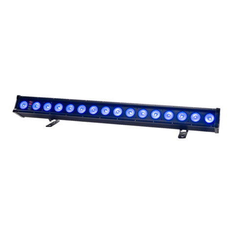
Delta UV ELP210/3AM Manual

ELP AM Series - Manual 2011 - 042011 Copyright Delta UV ©
Page 1
ELP AMALGAM RANGE
INSTALLATION AND MAINTENANCE
MANUAL

ELP AM Series - Manual 2011 - 042011 Copyright Delta UV ©
Page 2
CERTIFICATIONS
The Delta UV ELP range of Ultraviolet Sanitation Systems for pools, spas, water features and
ponds are certified and listed by the following independent laboratories and authorities.
Certifications can be independently confirmed by visiting the specific websites shown with each
certification below :
o Listed under UL standard UL1081/UL1563 –US
o Certified To Canadian CAN/CSA Standard C22.2 No. 218.1
o MET Listing #
o http://
o Certified to NSF-50 Sanitation Standard
o NSF Listing #
o http://www.nsf.com/Certified/Pools/
o EPA Established #075659-FRA-001
Delta UV declares to be in conformance with the applicable provisions of the Code of Federal
Regulations (CFR) requirements including Title 21, Chapter 1, Subchapter J pertaining to
radiological health.
All Delta UV systems are sized to match the maximum flow rate of the circulation pump(s).
Proper installation calls for 100% of the circulation system flow to pass through the UV reactor.
Slip stream or bypass installations which direct only a portion of the recirculation flow to pass
through the UV reactor cannot be guaranteed to produce the required sanitation and
dechloramination results and should be avoided. Delta UV systems are sized by confirming the
maximum GPM flow though the reactor to produce a dose of 60mJ/sec/cm2, which is the proper
UV-C dose for effective 99.99% (4 log minimum) kill rate for bacteria, algae and even chlorine
resistant parasites such as cryptosporidium, giardia, legionnella, and shigella.
DELTA ULTRAVIOLET CORPORATION
1535 W. Rosecrans Avenue
Gardena, CA 90249
Local Phone: 1-310-323-6400
Fax: 1-310-323-6403
Email: [email protected]

ELP AM Series - Manual 2011 - 042011 Copyright Delta UV ©
Page 3
IMPORTANT SAFETY INSTRUCTIONS
WARNING: This product should be installed by a professional service technician or
similar person, qualified in electrical equipment installation. Improper Installation and/or
operation could cause serious injury, property damage, or death. Improper installation
and/or operation will void the Limited Warranty
WARNING: When using electrical products, basic precautions should always be
followed, including the following:
1. READ AND FOLLOW ALL INSTRUCTIONS
2. WARNING-A wire connector is provided on this unit to connect a minimum 8 AWG (8.4
mm2) solid copper conductor between this unit and any metal equipment, metal
enclosures of electrical equipment, metal water pipe, or conduit within 5 feet (1.5 m) of
the unit.
3. WARNING – For indoor use only. This unit is not intended for outdoor use.
4. WARNING – This product must be connected to ground-fault circuit-interrupter.
5. WARNING –Risk of Electric Shock. Install at least 5 feet (1.5 m) from inside wall of hot
tub or spa or swimming pool using nonmetallic plumbing
6. SAVE THESE INSTRUCTIONS

ELP AM Series - Manual 2011 - 042011 Copyright Delta UV ©
Page 4
IMPORTANT SAFETY INSTRUCTIONS
1. READ AND FOLLOW ALL INSTRUCTIONS
2. WARNING- Never look at the ultraviolet lamps when lit. This may cause severe
injuries or burns and may even lead to loss of eyesight
3. WARNING –. Do not touch the ultraviolet lamp with bare hands, as these would leave
impurities that shorten the life of the lamp. If you do touch it: clean with alcohol or white
vinegar.
4. WARNING – Never unscrew the quartz tube sealing nut when the reactor is on load as
the quartz tube could be blown out of the reactor with force and injure you
5. WARNING – Do not use the reactor if the power supply wire is worn or damaged. In this
case it should be replaced.
6. WARNING – If the connecting cable between the reactor and the electrical cabinet is
damaged, it must be replaced by a special cable available as a spare part.
7. WARNING – Even when stopped, power is present in the electrical unit so make
sure that the main power supply upstream of the electrical cabinet is switched off before
carrying out any work on the equipment.
8. WARNING – To avoid electric short-circuits; do not place the electric wires or the reactor
in the pool water or in any other maintenance or cleaning fluid.
9. WARNING – Do not restart the system until the electric unit, the covers exterior elements
of the reactor are correctly back in place.
10. WARNING - Do not simply throw the old lamps into the trash as they contain Mercury
and must be disposed of properly. www.lamprecycle.org
11. SAVE THESE INSTRUCTIONS

ELP AM Series - Manual 2011 - 042011 Copyright Delta UV ©
Page 5
IMPORTANT SAFETY INSTRUCTIONS
IMPORTANT: Follow the instructions contained herein EXACTLY and IN THE ORDER
LISTED. Once installed and maintained properly,your UV system will provide years of
successful operation
RECOMMENDATIONS
The reactor must be installed in a technical room, protected from rain.
The reactor must be installed in a dry zone.
The installation zone temperature must be within 0°C and 40°C.
Ambient humidity must be < 80%.
Make sure you choose a position where the lamp can be taken out – the AVAILABLE
HEIGHT should be DOUBLE the total height of the appliance.
The reactor must be installed after the filter(s).
Keep any sources of hydrochloric acid vapours away from the installation.
● Maximum cable length between the UV reactor and the electrical unit
is 3 meters.
● Before accessing the connection terminals, ensure that all supply
circuits are disconnected.
● The reactor installation as a whole must be protected with a suitably
adapted circuit breaker.
(See A. Technical characteristics)
● Check that cable complies with legislation and the required power level.
(See A. Technical characteristics)
●Do not use the Delta UV reactor for any other use than that for which it
was designed.

ELP AM Series - Manual 2011 - 042011 Copyright Delta UV ©
Page 6
TABLE OF CONTENTS : Pages
A. TECHNICAL SPECIFICATION………………………………………………………………….8
B. INSTALLATION INSTRUCTION………………………………………………………………...10
C. STARTING UP…………………………………………………………………………………….13
D. USE………………………………………………………………………………………………...14
E. MAINTENANCE…………………………………………………………………………………..16
F. TROUBLESHOOTING……………………………………………………………………………22
G. ALARM CONTACT………………………………………………………………………………..22
ANNEX 1: Clearance dimensions - Blown up view - Designation
ANNEX 2: Electrical diagrams

ELP AM Series - Manual 2011 - 042011 Copyright Delta UV ©
Page 7
We thank you for choosing a disinfection reactor from the UV AM range.
Our equipment has been designed to provide long term, reliable service.
Our equipment has been designed to give you reliable and safe operation for many years to
come.
The reactors in the UV AM range have been designed for speed and ease of installation.
Their design also makes them easy to maintain
Read these instructions carefully in order to optimize the operation of your reactor.
Instruction Manual Icon Identification
To aid the reader in understanding the importance of various items contained within this
manual, Icons are used to throughout this manual to identify the area of importance of
the selected item. The five icons used and their significance are:
This icon advises the reader that the information following is of key importance
This Icon alerts the reader that the information noted regards a potential safety hazard
This Icon alerts the reader that the information noted regards a potential heat related
safety issue
This Icon alerts the reader that the information noted regards a potential vision related
safety issue
This Icon alerts the reader to use gloves when touching an object

ELP AM Series - Manual 2011 - 042011 Copyright Delta UV ©
Page 8
A. TECHNICAL SPECIFICATIONS
Reactor
ELP210/3AM
ELP310/3AM
ELP314/3AM
ELP414/3AM
ELP514/3AM
ELP516/3AM
ELP616/3AM
ELP716/3AM
ELP816/3AM
ELP1016/3AM
Material
Stainless steel 316 L
Finish
Pickling and passivated
Maximum
pressure
3 bars
Reactor diameter /
length (in)
10 x 39,09
10 x 39,09
14 x 39,09
14 x 39,09
14 x 39,09
16 x 39,09
16 x 39,09
16 x 39,09
16 x 39,09
16 x 39,09
Total Length( in)
46
46
46
46
46
46
46
46
46
46,5
Volume (US
Gallon)
13.95
13.62
23.24
22.91
22.58
30.29
29.96
29.63
29.3
28.64
Connection type
LAP JOINT FLANGE, Stainless steel 316 L
Standard
connection
6 inches
6 inches
8 inches
8 inches
8 inches
8 inches
10 inches
10 inches
12 inches
12 inches
ELECTRICAL UNIT
Type
Painted steel
Dimensions (in)
23.6 x 15.7
x 9.8”
23.6 x 23.6
x 9.8”
23.6 x 23.6
x 9.8”
23.6 x 23.6
x 9.8”
31.5 x 23.6
x 11.8"
31.5 x 23.6
x 11.8"
31.5 x 23.6
x 11.8"
39.4 x 23.6
x 15.7”
39.4 x 23.6
x 15.7”
39.4 x 31.5
x 15.7”
Power supply
230V single
phase
230V single
phase
230V single
phase
230V single
phase
230V single
phase
230V single
phase
230V single
phase
230V single
phase
230V three
phases
230V three
phases
Circuit protector
Ampacity
10 A
10 A
10 A
10 A
10 A
10 A
16 A
16 A
16 A
16 A
Curve of release
of the circuit
breaker
Curve C
Curve C
Curve C
Curve C
Curve C
Curve C
Curve C
Curve C
Curve C
Curve C
Power supply
conductor
60°C copper 2X14 AWG + GROUND
60°C copper 2X12AWG
+ GROUND
60°C copper 3X12AWG
+ GROUND
On / Off switch
Yes
Power indicator light
Yes
UV indicator light
Yes
UV SENSOR
Yes
Temp sensor
Yes
Display
Digital hour counter + Millenium III
Protection index
IP 54
UV Lamp
Number of lamp
2
3
3
4
5
5
6
7
8
10
Electrical power
594W
891 W
891 W
1188 W
1485 W
1 485 W
1782 W
2 079 W
2376 W
2970 W
Unit UV-C power
85 W
85 W
85 W
85 W
85 W
85 W
85 W
85 W
85 W
85 W
Total UV-C power
170 W
255 W
255 W
340 W
425 W
425 W
510 W
595 W
680 W
850 W
Service life of
lamps
13 000 h
Performances
Flow rate at >40
mJ/cm²
440 gpm
650 gpm
695 gpm
920 gpm
1140 gpm
1260 gpm
1510 gpm
1760 gpm
2010 gpm
2520 gpm
(1) At the end of the lifetime of the lamps, at the most unfavorable point in reactor, for a transmittance of 98%.

ELP AM Series - Manual 2011 - 042011 Copyright Delta UV ©
Page 9
THE ELECTRICAL UNIT: CONFIGURATION
- Position the unit away from water.
- The ventilator must not be blocked.
- Maximum cable length between the UV reactor and the electrical unit is 3 meters.
Electrical unit, external view:
Electrical unit, internal view:
7. 24Vdc Power
supply
connector block
6.circuit
breaker
8.Electronic
ballasts
1. Monitor
4. Manual
ON/OFF switch
2.Lamp
operating
indicator light
5. Default
indicator light
3.Power
indicator light

ELP AM Series - Manual 2011 - 042011 Copyright Delta UV ©
Page 10
B. INSTALLATION INSTRUCTIONS
ELP AMALGAM range reactors are ready to install, no work is required inside the reactor.
B. 1 RECOMMENDED INSTALLATION DIAGRAM
The reactor must be installed after the filter(s).
The full flow of the circulation system must flow through the UV reactor chamber.
However, in order to provide serviceability of the UV reactor without the necessity of
shutting down the circulation system, it is desired to provide a piping bypass system in
the circulation piping. The pipe size of the bypass should be the same size pipe of the
circulation system at the bypass location. Three valves are required to accommodate a
full bypass of the UV reactor. One valve is a bypass valve that normally remains closed
at all times while the UV system is in operation, and two valves isolate the UV reactor (in
closed position) when accessing the reactor for normal service such as quartz tube or
wiper ring replacement).
If you use the bypass the water circulation go through the bypass (blue arrows)
If you do not used the bypass the water circulation go through the reactor (green arrows)
To isolate the UV reactor during the maintenance: Open the By-Pass
- Open the valve 1
- Close the valve 2 and the valve 3
After maintenance: Close the By-Pass
- Open the valve 2
- Open slowly the valve 3
- Close the valve 1
FILTER
PUMP
REACTOR
UV
BY-PASS
VALVE
SWIMMING
POOL
Valve 1
Valve 2
Valve 3

ELP AM Series - Manual 2011 - 042011 Copyright Delta UV ©
Page 11
B. 2 ELECTRICAL UNIT INSTALLATION
- Position the unit away from water.
- The ventilator must not be blocked.
- Maximum cable length between the UV reactor and the electrical unit is 3
meters.
B.3 WIRING DIAGRAM
Use copper conductors only
Permanently Connected Equipment Assembly with Ultra Violet Lamps,
Ballasts and Control.
The reactor could be turn on 24h/24 and anyway must be slaved to the filtration in order to
desinfect at the same time.
DIAGRAM: Wiring Terminal
Lug
(Provided with the
electrical unit)
Screw M6x20
(Provided with the
electrical unit)
Screw 6x30 minimum
(Not provided with
the electrical unit)
Use this hole
to fixe the
electrical unit
in the wall
Main Earthing Ground:
60°C copper. Conductors
size see page 8.
Neutral
Line
60°C copper conductors
For conductors size see
page 8.
Reactor Earthing Ground:
60°C copper. Conductors
size see page 8.

ELP AM Series - Manual 2011 - 042011 Copyright Delta UV ©
Page 12
- External interconnecting flexible cords must to be installed in a restricted access location only
accessible by qualified persons.
- External interconnecting flexible cords must be secured off the floor and to the mechanical
structure.
I15
Please report to the electrical diagram :
annex 2
During maintenance switch off the cabinet
and you can unplug the wires without risk.
24
124
Diagram : Terminal connections on the reactor
I15
24
124
Lug for vessel bonding to
the main earthing ground.
Lugs for vessel bonding
to the equipotential bond.
Equipotential bond.
You may use these lugs to connect exposed dead
metal that may become energized to the rest of the
exposed dead metal around the pool area.
Main earthing ground - Connected
to the supply ground.
The supply ground must be brought in the
junction box by the electrician at the time of
installation from the same point as the supply
conductors.
POOL & ASSOCIATED
METALIC EQUIPMENT

ELP AM Series - Manual 20112 – 05/12 Copyright Delta-UV ©
Page 13
C. STARTING UP
C.1 Starting the UV lamp
1
Check that the electrical connection is compliant.
2
Check that the top of the equipment is correctly positioned.
3
Switch on the reactor
4
Check that the lamps are working properly: the indicator light for each lamp
should be lit
5
Check that the hour counter is running
C.2 Calibration of the UV sensor
OPERATION for CALIBRATION
1. Turn on the on/off switch on the front of the electrical cabinet.
2. The UV C lamps will heat up to their maximum output level in 2 minutes (depending on
the temperature of the liquid being treated).
3. Now you have to calibrate the sensor in its liquid environment:
YOUR UV UNIT IS NOW DISINFECTING FOR THE INDICATED FLOW RATE A 100%.

ELP AM Series - Manual 20112 – 05/12 Copyright Delta-UV ©
Page 14
D. USE
D.1 MANUAL OF THE MONITOR BIO-UV MIII
ALERT MESSAGES:
The screen flashes when there is an alert message.
The alert messages are always shown on the secondary display and are independent of what is displayed on
the main display unit.
Display
Meaning of the alert
Solutions
This message appears when the temperature of the
reactor is excessive or if the reactor’s cover is
removed. The lamps are stopped automatically.
Check that enough water is flowing
through the installation.
This alert message can be cleared by pressing on the key "OK".
It is preferable to carry out a maintenance operation before clearing the fault.
This message appears when one or several lamps
are faulty.
The numbers show which of the lamps are faulty.
Diagnose the cause of the breakdown.
This message appears when the intensity of the
UVC radiation falls below the pre-alarm threshold.
Check that the quartz sleeves are clean.
Check that the UV sensor is clean.
N.B.: when the lamps have been operating for a certain number of hours, this message appears naturally (normal wear of the lamps)
This message appears when intensity of the UVC
radiation falls below the main-alarm threshold.
Check that the quartz sleeves are clean.
Check that the UV sensor is clean.
Chang the UV lamps.
These 2 messages cannot be cleared unless the problem has been resolved.
GENERAL INFORMATION:
Definition of the letter on the first display
R
means that the reactor is switched on and
operating.
● The screen is backlit: Just pressing on a key
switches the back lighting on for one minute.
R On
Monitor
operating
indicator
Secondary display
LEGEND
During 5s
or
or
During 5s
Reset counter at
zero
Radiance UV
management ()
C
D
B
A
Main Display

ELP AM Series - Manual 20112 – 05/12 Copyright Delta-UV ©
Page 15
CONTENT OF MENUS AND SUB-MENUS:
Use the + or – keys to change from one menu to another.
Press on key A for 5 seconds to enter a menu.
When the word "OFF" is displayed, this means that the display option is not available on your device.
A
Display of UVC intensity measured by the sensor.
N.B.: each time the lamp is changed, you MUST calibrate the sensor even if the display
already shows 100%.
A1
Calibrating the sensor:
● It is important to carry out this operation when commissioning the reactor and also when
changing a lamp even if the display already shows 100%.
● It is important to wait 5 minutes before carrying out the calibration, to allow the lamps to
heat up.
● If your device is equipped with the power regulator, it is ESSENTIAL to switch over to
manual regulation (100%) before calibrating the sensor..
B
Display of lamp operating time. It is recommended to reset this counter at zero when you
change a lamp.
B1
Reset the hour counter and the number of lamp start-ups at zero.
C
Display the reactor's total operating time since commissioning. This counter cannot be reset at
zero..
D
Display of the number of lamp start-ups carried out. Resetting at zero is linked to that of the
hour counter.
D.2 TEMPERATURE SENSOR
The temperature sensor is located inside the cover of the reactor.
If the temperature of the reactor is excessive, the system is switched off and the red
indicator lights.
In this case :
- control your pump, and if OK: Push the ‘OK’ button on the Millenium to reset
the default.
D.3 MICRO SWITCH
The micro- switch is located inside the cover of the reactor.
When the cover is open, the micro-switch are switch the UV lamps OFF, and the red
indicator lights.
When the cover is closed; push the ‘OK’ button on the Millenium to reset the default

ELP AM Series - Manual 20112 – 05/12 Copyright Delta-UV ©
Page 16
E. MAINTENANCE
E.1 REPLACE/REMOVE UV LAMPS: 10 minutes
NO TOOLS HAVE TO BE USED AND ARE NECESSARY TO REALIZE THESE OPERATIONS
except for removing and refitting the cover at the top.
When a lamp is defective (except when the set of 3 lamps is less than 4 000 h), we recommend
to change all lamps
1
YOU MUST STOP ABSOLUTELY THE POOL/SPA FILTRATION
SWITCH OFF the power supply on the front panel of the
electrical cabinet,
CLOSE the valves up- and downstream of the reactor on the
by-pass,
CUT the POWER source and EMPTY THE REACTOR.
2
Remove the bonnet at the top.
Do not remove the screw making the
watertightness of the quartz sleeve (it’s not necessary
to change only the lamps)
3
Remove each lamp connector, the ground connectors, and the
temperature connector
4
Make sure that UV lamps are sufficiently cooled before handling it.
5
Take the top of the lamp and disengage the lamp from the quartz
sleeve, keeping it correctly aligned with the axis.
Carry out this operation CAREFULLY without touching the bulb
with your fingers.
6
Put the new lamp by the ceramic cap without touching the body of the lamp
(if you do so, clean the lamp with a soft cloth and some methylated spirits)
7
Engage the lamp in the quartz sleeve keeping it correctly aligned
with the axis inside the equipment.
8
Plug the ground connector and each lamp connector (secure
connectors using the stainless steel nuts).

ELP AM Series - Manual 20112 – 05/12 Copyright Delta-UV ©
Page 17
9
Refit the bonnet.
10
Check the calibration of the UV-C ray measurement sensor.
(See chapter on the setting of the UV Monitor).
Open the valve, turn on the filtration, turn on the on/off switch

ELP AM Series - Manual 20112 – 05/12 Copyright Delta-UV ©
Page 18
E.2 CHANGE/CLEAN QUARTZ SLEEVES AND O-RINGS: 20 minutes
NO TOOLS HAVE TO BE USED AND ARE NECESSARY TO REALIZE THESE OPERATIONS.
Make the operations 1 to 5 of the remove UV lamps operation (see previous
page)
1
Drain the unit:
- unscrew at the bottom of the UV unit the stainless steel small nut
2
Unscrew the stainless steel holding the quartz sleeves and making
the watertightness
Remove the plastic washer.
3
Take out the quartz sleeve carefully:
Insert your thumb or another finger in the sleeve and slowly
withdraw the quartz sleeve until the O-ring comes free from its
housing.
8
Take hold of the quartz sleeve and extract it fully MAKING SURE
that you keep it correctly aligned with the axis.
9
The quartz sleeve exterior can normally be cleaned by using
acid or spirit vinegar or pH minus(liquid) with weak concentration.
(ratio of 4 parts water to one part acid).
Do not use abrasive cleaners.
REASSEMBLY
10
CAREFULLY insert the sleeve in the unit, keeping it correctly
aligned with the axis. Your medium or index finger will help you to
correctly drive and to find easier the socket at the bottom.
With a finger inside the sleeve, position the quartz in its socket at
the bottom of the equipment. The quartz should protrude slightly
(by the thickness of the O-ring),
it should not be dropped right to the bottom.
If the quartz is correctly positioned in the socket, when you press it,
it feels flexible (pneumatic effect)
11
Lubricate the new O-ring with edible fat or your saliva.
(New O-ring should be used at each quartz sleeve cleaning)
Position the O-ring around the sleeve
and push it fully home in its housing using your finger nail
(do not use any tool).

ELP AM Series - Manual 20112 – 05/12 Copyright Delta-UV ©
Page 19
12
Place the plastic washer inside the stainless steel thread.
Re-tighten the nut by hand, tightening it normally, to the
maximum.
13
Open the valve, start the filtration, when the unit is under pressure
the vessel is pressured, and then you can check that there is no
leakage in the quartz tube and at the watertightness.
14
Make the operations 6 to 10 of Replace/remove UV lamps
(see previous pages)

ELP AM Series - Manual 20112 – 05/12 Copyright Delta-UV ©
Page 20
E.3 QUARTZ SLEEVES : CLEANING IN PLACE
To set this operation, you need :
- To install a PVC tank with a tranparent tube with the following dimensions : Diameter 2’’,
length 20’’. This tube will be above a PVC valve.
- 1 liter of muriatic acid
STEP
OPERATION
1
Close the valves 2 and 3 et open the valve 1
2
Fill the PVC tank with 1 liter of muriatic acid
3
Open the valve 4
4
Open slowly the valve 5 till the level of the PVC goes down, then close
valve 5
5
Close valve 4
6
Leave it during 1 hour
7
Open the valve 5 and empty the UV reactor
8
Close the valve 4 and 5
9
Run the UV reactor on
- Open the valve 2
- Open slowly the valve 3
- Close the valve 1
Valve 1
Valve 2
Outlet
Valve 3 :
Inlet
Valve 4
Valve 5
Transparent PVC
tank
20’’
This manual suits for next models
9
Table of contents