smart home Chemical-Free Pool System User manual

I
.
SMARTHOMETM
Chemical-Free Pool System
OWNERS MANUAL
SMARTHOMETM
1’7171Daimler street
Irvine, CA. 92614
949-22l-9200
Thank you for purchasing the SMARTHOME Chemical-Free Pool System. Carefully an2
completely read these instructions before installing.
TABLE OF CONTENTS
System Description Page 1
Controller Description Page 2
System Installation Page 3
System Start-up and Operation Page 4
Maintenance Page 6
Troubleshooting Guide Page 7
Drawings Page 9
War&&y Page 10
SYSTEM DESCRIPTION
Each SMARTHOME System contains two main assemblies:
1. The CONTROLLER converts AC current to DC current for the cells, and controls the operating
time for the cells to maintain the correct concentration of chlorine, copper, and silver.
2.
The ELECTROLYTIC CELLS use DC current from the Controller to produce chlorine from a
low 3,000 ppm salt level maintained in your pool water, and a low level of copper, and S:_lver
ions.
Page 1
SMARTHOME.COM™ 1-800-SMART-HOME
949-221-9200 http://www.smarthome.com Order #3230
CONTROLLER DESCRIPTION
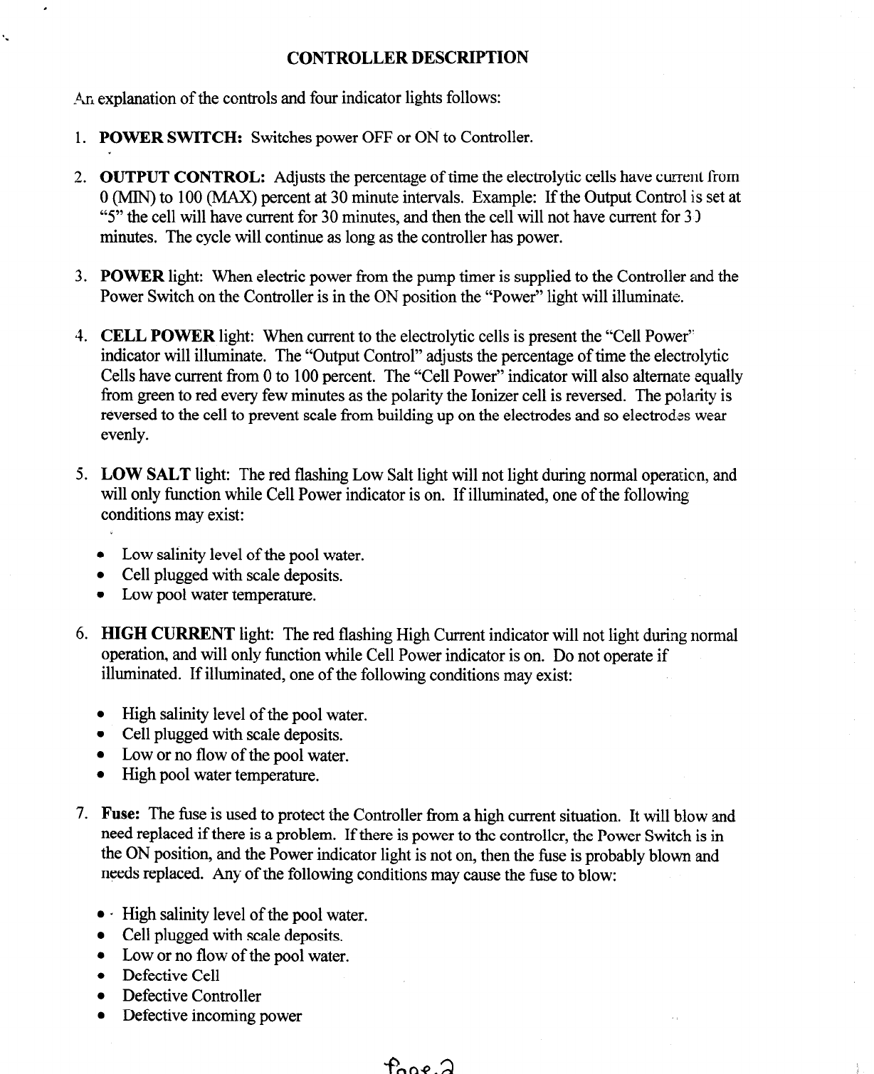
An explanation of the controls and four indicator lights follows:
1.
2.
3.
‘4.
5.
6.
7.
POWER SWITCH:
Switches power OFF or ON to Controller.
OUTPUT CONTROL:
Adjusts the percentage of time the electrolytic cells have current
Corn
0 (YbfIN)
to 100 (MAX) percent at 30 minute intervals. Example: If the Output Control is
setat
“5"
the cell will have current for 30 minutes, and then the cell will not have current for 31
minutes. The cycle will continue as long as the controller has power.
POWER light: When electric power from the pump timer is supplied to the Controller and the
Power Switch on the Controller is in the ON position the “Power” light will illuminate.
CELL POWER
light: When current to the electrolytic cells is present the “Cell Power”
indicator will illuminate. The “Output Control” adjusts the percentage of time the electrolytic
Cells have current from 0 to 100 percent. The “Cell Power” indicator will also alternate equally
from green to red every few minutes as the polarity the Ionizer cell is reversed. The polarity is
reversed to the cell to prevent scale from building up on the electrodes and so electrodes wear
evenly.
LOW SALT light: The red flashing Low Salt light will not light during normal operation, and
will only function while Cell Power indicator is on. If illuminated, one of the following
conditions may exist:
l
Low salinity level of the pool water.
l
Cell plugged with scale deposits.
l
Low pool water temperature.
HIGH CURRENT light: The red flashing High Current indicator will not light during nomlal
operation, and will only function while Cell Power indicator is on. Do not operate if
illuminated. If illuminated, one of the following conditions may exist:
l
High salinity level of the pool water.
l
Cell plugged with scale deposits.
l
Low or no flow of the pool water.
l
High pool water temperature.
Fuse: The fuse is used to protect the Controller from a high current situation. It will blow and
need replaced if there is a problem. If there is power to the controller, the Power Switch is in
the ON position, and the Power indicator light is not on, then the fuse is probably blown and
needs replaced. Any of the following conditions may cause the fuse to blow:
l
.
High salinity level of the pool water.
l
Cell plugged with scale deposits.
l
Low or no flow of the pool water.
l
Defective Cell
l
Defective Controller
l
Defective incoming power
--
SMARTHOME.COM™ 1-800-SMART-HOME
949-221-9200 http://www.smarthome.com Order #3230

INSTALLATION INSTRUCTIONS
1. Before installing the pool should be clean, pH balanced, stabilized (cyanuric acid) to 50 to 75
ppm., free of algae, the filter cleaned, and then shock the pool with chlorine to 5 ppm. Failure
to add the stabilizer will allow the sun to destroy the chlorine as fast as it is produced ant. you
will not be able to maintain your chlorine level. Do not proceed until you have added the
proper stabilizer level to your pool. You can purchase chlorine stabilizer (cyanuric acid) and a
test kit at your local pool dealer. Your stabilizer level will only need increased once or twice a
year as it is diluted due to water replacement.
2. Turn off the power to the pool equipment.
3. Install the cells on the return side of the filter, or after the heater if your pool has one. hutall the
cells so that water flows through the salt generator cell first. See FIG. 1Page 9. The salt
generator cell is installed on a horizontal pipe with electrodes below the pipe. See FIG. 2. The
Ionizer cell is installed on a vertical or horizontal pipe. See FIG. 3. The black line on the
ionizer cell must always be in line with the water flow. Glue the 1%”x 2” bushings into the 2”
tees using PVC glue if your existing pipe is 11/2)‘.
Do not use the bushings if your existing pipe
is 2” PVC. Glue the tees in place using PVC glue making sure they are installed so nc air will
be trapped in the cells. If you are not sure how to install the cells you should have a swirming
pool contractor do it for you.
4. Mount the controller on a wall or vertical surface where the wires will reach the cells. See FIG.
1. It is best to install the controller where it is protected from the sun and weather. To mount,
loosen the 4 screws on the cover and carefully remove the cover. Do not remove the plastic
screws from the cover. Insert the 4 #8 x 2” screws into the four comer holes on the controller
and tighten evenly so that the heat sinks are snug against the wall. Do not over tighten, and do
not remove the heat sinks. There must be an air space between the controller and the wall for
ventilation.
5. The controller must be wired so that it has AC power only when the pump is running. For in
ground pools the controller must be hard wired to comply with NEC rules. We recommend
using %”liquid tight flex. The ground wire must be # 12 or larger and the others must be # 16
or larger. Your controller will be set for 230 volt AC input power. For 115 volt AC power see
# 7 below.
6. For 230 volt AC connect one hot wire to the loose black wire attached to the power switch on
the cover using the wire nut provided. Connect the other hot wire to the N (AC) on the power
supply terminal strip. Connect the ground wire to the ground terminal on the power supply
terminal strip. See step 8 if you need to switch the input voltage. The wiring should be
performed by a licensed electrician if you are not sure how to wire the AC power. Failure to
wire the power supply properly may damage the power supply and will void warranty.
7. For 115 volt AC power the switch in the front of the power supply must be switched to 115
volts AC. See step 8 to switch the input voltage. For 115volt AC connect the hot wire to the
loose black wire attached to the power switch on the cover using the wire nut provided.
Connect the neutral wire to the N (AC) on the power supply terminal strip. Connect the ground
wire to the ground terminal on the power supply terminal strip. The wiring should be
performed by a licensed electrician if you are not sure how to wire the AC power. Failure to
wire the power supply properly may damage the power supply and will void warranty.
Page
3
SMARTHOME.COM™ 1-800-SMART-HOME
949-221-9200 http://www.smarthome.com Order #3230
‘.
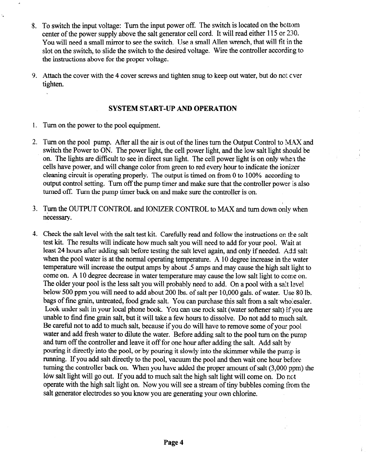
8. To switch the input voltage: Turn the input power off. The switch is located on the bottom
center of the power supply above the salt generator cell cord. It will read either 115
or
230.
You will need a small mirror to see the switch. Use a small Allen wrench, that will fit in the
slot on the switch, to slide the switch to the desired voltage. Wire the controller according to
the instructions above for the proper voltage.
9. Attach the cover with the 4 cover screws and tighten snug to keep out water, but do not ever
tighten.
SYSTEM START-UP AND OPERATION
1. Turn on the power to the pool equipment.
2. Turn on the pool pump. After all the air is out of the lines turn the Output Control to MAX and
switch the Power to ON. The power light, the cell power light, and the low salt light should be
on. The lights are difficult to see in direct sun light. The cell power light is on only whe;? the
cells have power, and will change color from green to red every hour to indicate the ionizer
cleaning circuit is operating properly. The output is timed on from 0 to 100% according to
output control setting. Turn off the pump timer and make sure that the controller power is also
turned off. Turn the pump timer back on and make sure the controller is on.
3. Turn the OUTPUT CONTROL and IONIZER CONTROL to MAX and turn down only when
necessary.
4. Check the salt level with the salt test kit. Carefully read and follow the instructions on.the salt
test kit. The results will indicate how much salt you will need to add for your pool. Wait at
least
24
hours after adding salt before testing the salt level again, and only if needed. Add
salt
when the pool water is at the normal operating temperature. A 10 degree increase in the water
temperature will increase the output amps by about .5 amps and may cause the high salt light to
come on. A 10 degree decrease in water temperature may cause the low salt light to come on.
The older your pool is the less salt you will probably need to add. On a pool with a s$t level
below 500 ppm you will need to add about 200 lbs. of salt per 10,000 gals. of water. Use 80 lb.
bags of fine grain, untreated, food grade salt. You can purchase this salt from a salt wholesaler.
Look under salt in your local phone book. You can use rock salt (water softener salt) if you are
unable to find tine grain salt, but it will take a few hours to dissolve. Do not add to much salt.
Be careful not to add to much salt, because if you do will have to remove some of your pool
water and add fresh water to dilute the water. Before adding salt to the pool turn on the pump
and turn off the controller and leave it off for one hour after adding the salt. Add salt by
pouring it directly into the pool, or by pouring it slowly into the skimmer while the pump is
running. If you add salt directly to the pool, vacuum the pool and then wait one hour before
turning the controller back on. When you have added the proper amount of salt (3,QOOppm) the
low salt light will go out. If you add to much salt the high salt light will come on. Do not
operate with the high salt light on. Now you will see a stream of tiny bubbles coming from the
salt generator electrodes so you know you are generating your own chlorine.
Page 4
SMARTHOME.COM™ 1-800-SMART-HOME
949-221-9200 http://www.smarthome.com Order #3230
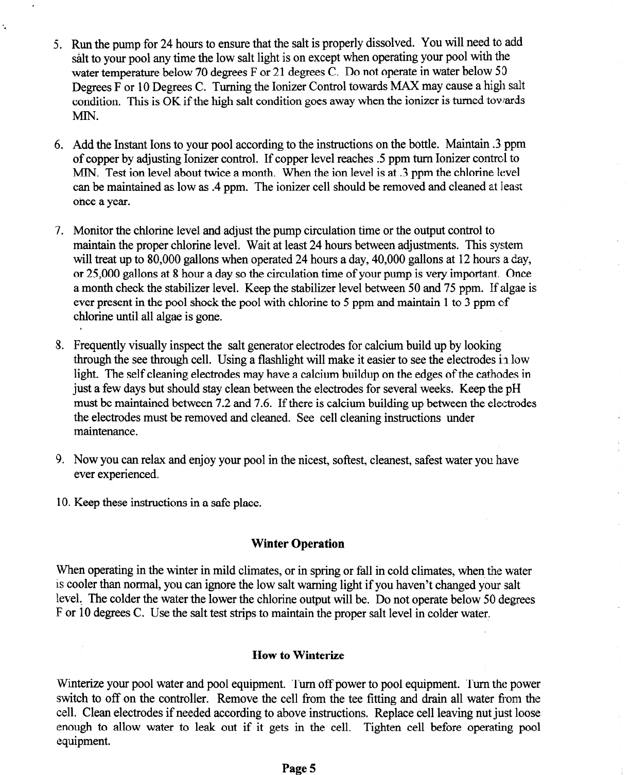
5. Run the pump for 24 hours to ensure that the salt is properly dissolved. You will need to add
salt to your pool any time the low salt light is on except when operating your pool with the
water temperature below 70 degrees F or 21 degrees C. Do not operate in water below 53
Degrees F or 10 Degrees C. Turning the Ionizer Control towards MAX may cause a high salt
condition. This is OK if the high salt condition goes away when the ionizer is turned towards
MIN.
6. Add the Instant Ions to your pool according to the instructions on the bottle. Maintain .3 ppm
of copper by adjusting Ionizer control. If copper level reaches .5 ppm turn Ionizer contrcl to
MIN. Test ion level about twice a month. When the ion level is at .3 ppm the chlorine level
can be maintained as low as .4 ppm. The ionizer cell should be removed and cleaned at least
once a year.
7. Monitor the chlorine level and adjust the pump circulation time or the output control to
maintain the proper chlorine level. Wait at least 24 hours between adjustments. This system
will treat up to 80,000 gallons when operated 24 hours a day, 40,000 gallons at 12hours a day,
or 25,000 gallons at 8 hour a day so the circulation time of your pump is very important. Once
a month check the stabilizer level. Keep the stabilizer level between 50 and 75 ppm. If algae is
ever present in the pool shock the pool with chlorine to 5 ppm and maintain 1to 3 ppm of
chlorine until all algae is gone.
5. Frequently visually inspect the salt generator electrodes for calcium build up by looking
through the see through cell. Using a flashlight will make it easier to see the electrodes i.3low
light. The self cleaning electrodes may have a calcium buildup on the edges of the cathodes in
just a few days but should stay clean between the electrodes for several weeks. Keep the pH
must be maintained between 7.2 and 7.6. If there is calcium building up between the electrodes
the electrodes must be removed and cleaned. See cell cleaning instructions under
maintenance.
9. Now you can relax and enjoy your pool in the nicest, softest, cleanest, safest water you have
ever experienced.
10. Keep these instructions in a safe place.
Winter Operation
When operating in the winter in mild climates, or in spring or fall in cold climates, when,the water
is cooler than normal, you can ignore the low salt warning light if you haven’t changed your salt
level, The colder the water the lower the chlorine output will be. Do not operate below 50 degrees
F or 10 degrees C. Use the salt test strips to maintain the proper salt level in colder water.
How to Winterize
‘Winterizeyour pool water and pool equipment. Turn off power to pool equipment. Turn the power
switch to off on the controller. Remove the cell from the tee fitting and drain all water from the
cell. Clean electrodes if needed according to above instructions. Replace cell leaving nut just loose
enough to allow water to leak out if it gets in the cell. Tighten cell before operating pool
equipment.
Page 5
SMARTHOME.COM™ 1-800-SMART-HOME
949-221-9200 http://www.smarthome.com Order #3230
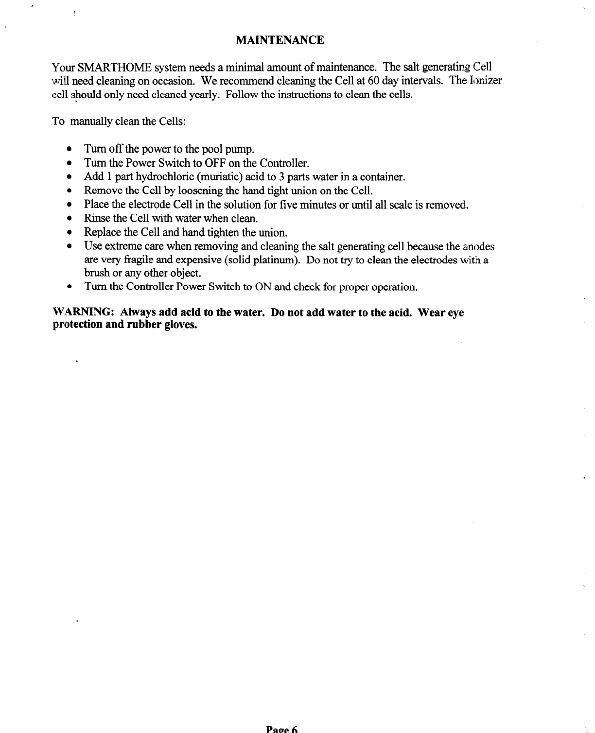
MAINTENANCE
Your
SMARTHOME system needs a minimal amount of maintenance. The salt generating Cell
will need cleaning on occasion. We recommend cleaning the Cell at 60 day intervals. The Ionizer
cell should only need cleaned yearly. Follow the instructions to clean the cells.
To manually clean the Cells:
Turn off the power to the pool pump.
Turn the Power Switch to OFF on the Controller.
Add 1part hydrochloric (muriatic) acid to 3 parts water in a container.
Remove the Cell by loosening the hand tight union on the Cell.
Place the electrode Cell in the solution for five minutes or until all scale is removed.
Rinse the Cell with water when clean.
Replace the Cell and hand tighten the union.
Use extreme care when removing and cleaning the salt generating cell because the anodes
are very fragile and expensive (solid platinum). Do not try to clean the electrodes witi a
brush or any other object.
Turn the Controller Power Switch to ON and check for proper operation.
WARNING: Always add acid to the water. Do not add water to the acid. Wear eye
protection and rubber gloves.
SMARTHOME.COM™ 1-800-SMART-HOME
949-221-9200 http://www.smarthome.com Order #3230

TROUBLESHOOTING GUIDE
PROBLEM
1.
Power light not on. A.
B.
C.
D.
2. Cell Power light not on, but A.
Power light on.
B.
3. Low Salt light flashing. A.
B.
4. High Salt light flashing.
5. Blown fuse.
C.
A.
B.
C.
A.
B.
C.
CAUSE
No AC power to controller.
Controller Power switch is in
OFF position.
Blown fuse.
Defective Controller.
Controller is in off cycle.
Defective Controller.
Salt level low.
Water Temperature has
cooled significantly.
Scale build up on Cell.
Salt level high.
Water Temperature has
warmed significantly.
Scale build up on Cell.
Damaged Cell
Defective Controller.
Incoming power problem.
SOLUTION
Check incoming AC potl’er.
Switch to ON position.
Replace fuse. See Problem if 4.
Check for proper operation.
Momentarily turn Outpxt Control
to MAX and Cell Power light will
illuminate.
Check for proper operatiw.
Add more salt to water.
Ignore light if temperature is
significantly below norms1
operating temperature.
Check Cell and clean if
necessary.
Check salt level and dilute water.
Check salt level and dilute water.
Shut system off until problem is
solved.
Check Cell and clean if
necessary.
Check Cell and clean if
necessary.
Check for proper opet-zsti3n.
Check incoming AC power.
Note: Replace fuse wit;?same
rated fuse.
Page 7
SMARTHOME.COM™ 1-800-SMART-HOME
949-221-9200 http://www.smarthome.com Order #3230

7. Gray
or brown staining on
pool surface.
CAUSE SOLUTION
A. Ionizer Control Setting to Turn Ionizer Control setting to
low. MAX until level is normal.
B. Output Control setting to
low. Increase setting to MAX until
level is normal.
C. Run time to short.
D. Algae problem.
Increase pump timer run time.
Add Instant Ions or other
Algaecide.
E. Electrodes are worn.
F. Defective Controller.
A. pH level isway to high.
B. Copper level is way to high
C. Other chemistry problem.
Check and replace if nec,:ssary.
Check for proper opera&x.
Lower pH to 7.2 and maintain at
7.2 to 7.6.
Turn Ionizer Control
to MIN.
Check water chemisny.
Page 8
SMARTHOME.COM™ 1-800-SMART-HOME
949-221-9200 http://www.smarthome.com Order #3230

SMARTHOMETM
Chemical-Free Pool System Drawings
IONIZER CELL
-
GROUND
CONTROLLER
-
PUMP
TIMER
r
SALT GENERATOR CELL
-1
,-
PUMP-’
I_
I
HEATLR FILTER
/
-4
w
PUMP
P0WE.R
J
TO POOL
FIG. 1
P
FROM POOL
NOT OK
OK NOT OK NOT OK
SALT GENERATOR CELL
OK OK
OK
OK
NOT
OK
Ionizer Cell
FIG. 2
FIG. 3
Page 9
SMARTHOME.COM™ 1-800-SMART-HOME
949-221-9200 http://www.smarthome.com Order #3230

L
SMARTHOMETM
Chemical-Free Pool System
WARRANTY
SMARTHOME warrants the Chemical-Free Pool System for three years from date of purchase.
We will repair or replace without charge, any defects due to faulty material or workmanship.
Please return the complete unit, transportation prepaid, to SMARTHOME.
Warranty Exclusions
This warranty does not apply to damage resulting from tampering, accident, abuse, negligence,
fire, flood, freezing, improper operation, maintenance, or storage.
Total Obligations
The forgoing constitutes the entire liability of SMARTHOME to the original purchaser ::hc
Chemical-Free Pool System. SMARTHOME makes no other warranty of any kind whatsoever,
expressed or implied. In no event will SMARTHOME be liable to the owner for direct, indirect,
incidental or consequential loss, damage or economic injury to any person or property arising out
of or relating to the use of the Chemical-Free Pool System except as expressly set forth herein.
This warranty gives you specific legal rights and you may also have other rights which vary from
state to state.
POST CARD BELOW MUST BE RETURNED WITHIN 30 DAYS OF PURCHASE TO:
SMARTHOMETM
17171Daimler street
Irvine, CA. 92614
949-22l-9200
___________________________
CUT HERE l--(-J REMOVE ___________________________
,
PRODUCT WARRANTY REGISTRATION CARD
Xill-lk:
Date Purchased: -_-
Address: Purchased From: ---
* -- -___--__.
Phone#: ( ) Model No.:
Chemical-Free Pool System
.
Page 10
SMARTHOME.COM™ 1-800-SMART-HOME
949-221-9200 http://www.smarthome.com Order #3230
Other smart home Lighting Equipment manuals

Popular Lighting Equipment manuals by other brands


Velux
Velux Integra CVP-5 Series manual

Sunoptic Surgical
Sunoptic Surgical Titan 400HP Operator's manual

EuroLite
EuroLite AKKU Dot 1 user manual

Kampa
Kampa SabreLink 30 Installation and operating manual

Hayward
Hayward Pro Logic Operation manual

Chauvet Professional
Chauvet Professional onAir IP Panel 2 user manual