Delta DV-3200 User manual

R
PLL SYNTHESIZER STEREO RADIO WITH
COMPACT DISC PLAYER DIGITAL
S-M
2
SCN
3
RPT
4
SHF
OPEN
RX
DV D/CD/MP3 P L AYER
PWR
REG
1
AMS/
PUSH
SE L
5 6
TA
PTY
AF
ENT
MU T
MOD
BND
SW
MENU

2
CONTENTS
Page
Disassembly Instructions ........................................................................................................................................ 3
Disassembly Diagram............................................................................................................................................. 4
Operation Check..................................................................................................................................................... 5
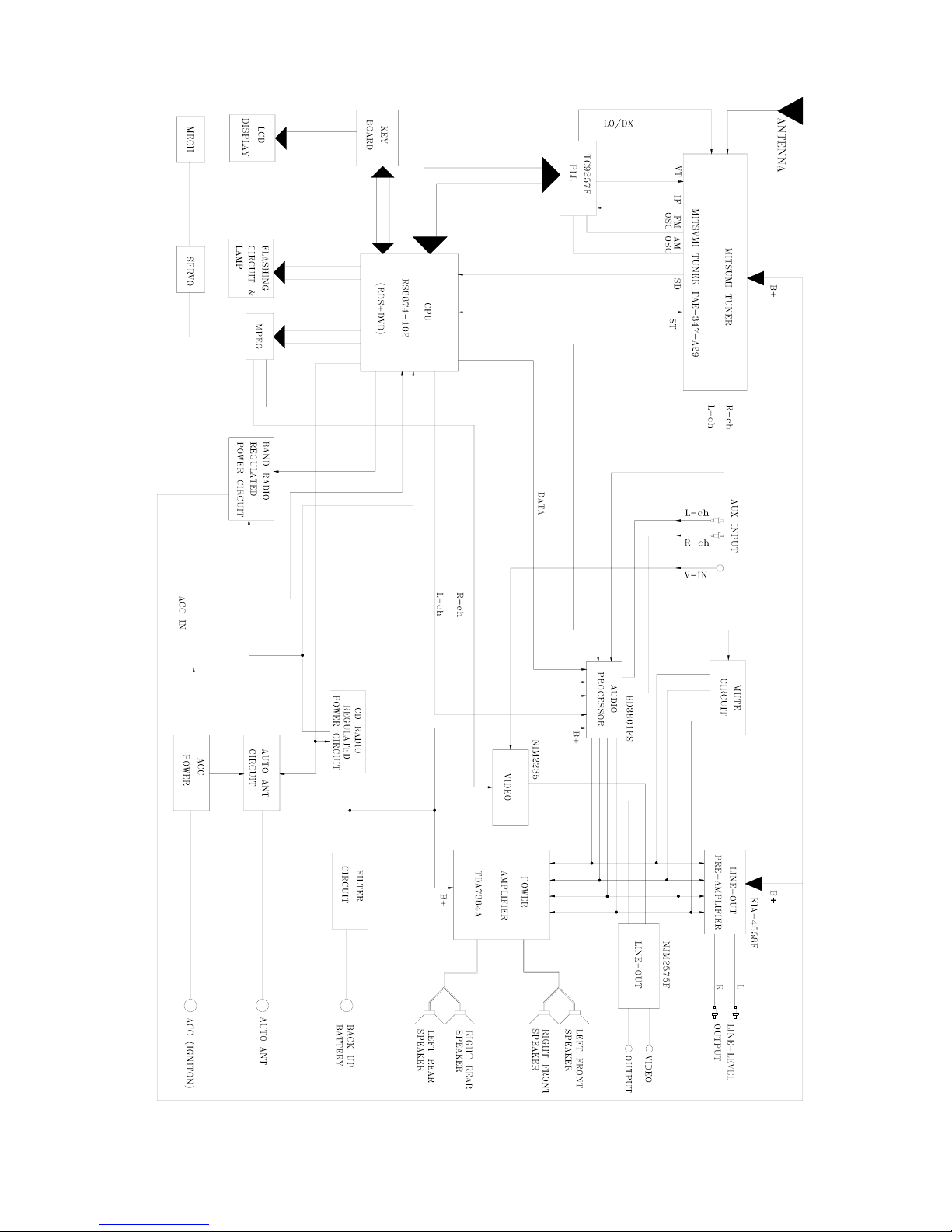
Block Diagram ........................................................................................................................................................ 6
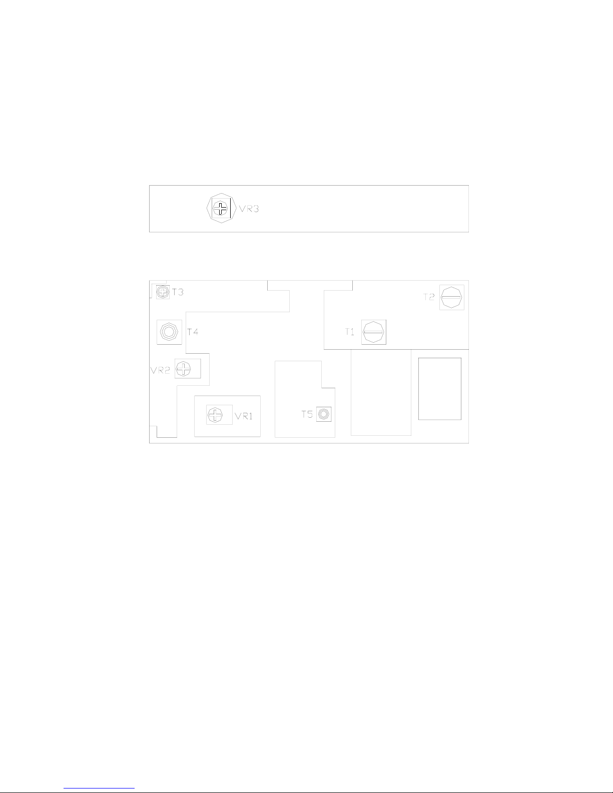
Alignment Locations ............................................................................................................................................... 7
Alignment Procedures ............................................................................................................................................ 8
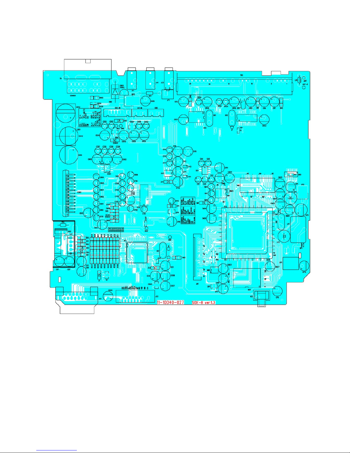
Printed Circuit Boards........................................................................................................................................... 10
Exploded Views (Panel)........................................................................................................................................ 20
Exploded View Parts Lists (Panel)........................................................................................................................ 21
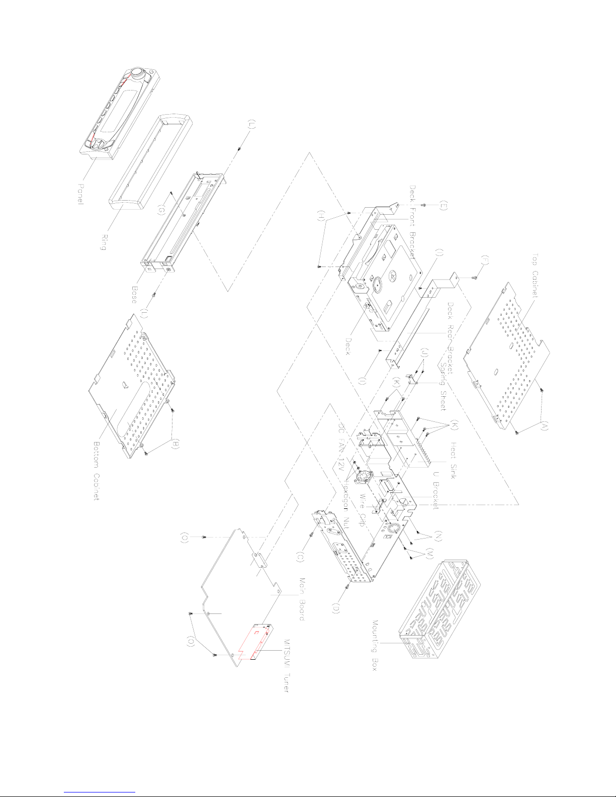
Exploded Views (Cabinet) .................................................................................................................................... 22
Exploded View Parts Lists (Cabinet) .................................................................................................................... 23
Schematic Diagram .............................................................................................................................................. 25
Electrical Parts List ............................................................................................................................................... 30
Specifications........................................................................................................................................................ 37

3
DISASSEMBLY INSTRUCTIONS
1. Using the unlock key that came with the unit or a similar tool, unlock the Mounting Box and remove toward the
rear of the unit.
2. Remove two screws (A) located on the rear of the top cabinet then remove the Top Cabinet.
3. Remove two screw (B) located on the rear of the bottom cabinet then remove the Bottom Cabinet.
4. Remove the screw (C) and (D) from on the left side of the U bracket.
Remove the screw (E) and (F) from on the right side of the U bracket.
5. Take out the Panel and remove the Ring.
6. Remove the screw (G) from on the front side of the base and remove two screws (H) from under the front
deck bracket then remove the Front Deck Bracket.
Remove two screws (I) from under the rear deck bracket then remove the Rear Deck Bracket.
7. Remove two screws (J) from on the Heat Sink then remove the Spring Sheet.
8. Remove five screws (K) from on the Heat Sink then remove the Heat Sink.
9. Remove two screws (L) from each side of the base then remove the Base.
10. Remove two screws (M) from on the back of the U bracket then remove the DC FAN 12V.
Remove two screws (N) from on the back of the U bracket then remove the Wire Clip.
11. Remove three screws (O) from under the main board then remove the Main Board.

4
DISASSEMBLY DIAGRAM

5
OPERATION CHECK
GENERAL SPECIFICATIONS OF SIGNAL
Standard frequency
Signal output
Modulation
FM
MW
LW
FM
MW
LW
MW
FM Stereo
98.1 MHz (87.5, 108 MHz)
1000 kHz (522, 1620 kHz)
200 kHz (144, 288 kHz)
1 mV
5 mV
5 mV
400 Hz 30% MOD.
1 kHz 75 kHz DEV.
90%forLonlyor
Ronlypilotlevel10%
AF output level FM/MW/LW
Power source voltage DC 14.0V (Backup voltage is the same as this)
AF load impedance 4 ohm pure resistance
Balance Center position of level
Tone Center position
The signal strength read in this section is voltage on the antenna.
TestDiagram
4-SPEAKER
VTVM
DISTORTION
METER
2-SPEAKER
FRONT
SPK.
SPK.
FL.
RL.
SPR.
MAIN UNIT
AM SG
VTVM ANTANNA
DUMMY
FM SG
MODULATOR
STEREOS
MPX
ANT
FRONT
SPK.
SPE.
FR.
RR.
4-SPEAKER
SPK.
2-SPEAKER
POWER ANTANNA
ACC (DV14.4V)
GROUND
BACK UP (14.4V)

6
BLOCK DIAGRAM (RADIO SECTION)

7
BLOCK DIAGRAM (DVD SECTION)

8
ALIGNMENT LOCATIONS
MITSUMI TUNER

9
ALIGNMENT PROCEDURES
FM ADJUSTMENT
Equipment Required
zAM IF/RF signal generator
zSolid-state voltmeter (SSVM)
zRegulated DC power supply
z2-CH voltmeter
zDistortion meter
FM Alignment Using FM Signal Generator
Note: Press the radio power switch to on the radio. Signal generator output must be kept as low as possible
to avoid overload and clipping.
Step Generator
Coupling
Generator Display
Setting
Adjustment Remarks
Stereo
Separation
Signal
Generator
to antenna
receptacle
98.1 MHz
Int. 1 kHz
Dev. 75 kHz
L+R = 90 %
pilot = 10 %
98.1 MHz
VR1
Adjust AF
output power
at maximum
separating
more than 30 dB
FM SNC
Adjustment
98.1 MHz
Dev. 75 kHz
L+R=90 %
Int. 1 kHz
60dBµV output
98.1 MHz
@ 40 dBµ
98.1 MHz
VR2
Stereo Separation
25 dB (±5 dB)
Stop
SENS.
Signal Generator
to antenna
receptacle
98.1 MHz
Mod. 1kHz
Dev 75kHz
98.1 MHz
VR3
Adjust AF to
stop station.
Note: The tuner module is well-adjust and adjustment is not recommended.

10
PRINTED CIRCUIT BOARDS
MAIN BOARD
TOP VIEW

11
MAIN BOARD
BOTTOM VIEW

12
KEY BOARD
TOP VIEW

13
KEY BOARD
BOTTOM VIEW

14
CD SERVO BOARD
TOP VIEW

15
CD SERVO BOARD
BOTTOM VIEW

16
REMOTE BOARD
TOP VIEW

17
REMOTE BOARD
BOTTOM VIEW

18
FRONT BOARD
TOP VIEW

19
FRONT BOARD
BOTTOM VIEW

20
EXPLODED VIEW
PANEL
Table of contents
Other Delta Car Receiver manuals