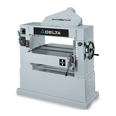
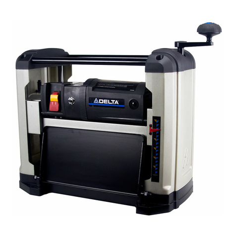
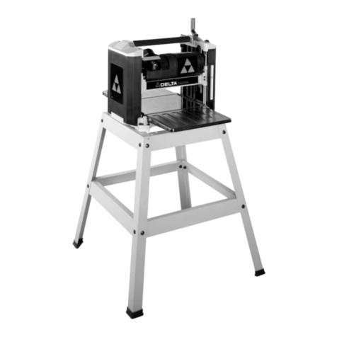
Delta 22-470 User manual

INSTRUCTION MANUAL
DATED 6-28-99 PART NO. 1342457
©Delta International Machinery Corp. 1999
24" Planer
(Model 22-470, Three Phase)

2
TABLE OF CONTENTS
SAFETY RULES. . . . . . . . . . . . . . . . . . . . . . . . . . . . . . . . . . . . . . . . . . . . . . . . . . . . . . . . . . . . . . . . . . . . . . . . . . . . . . . . 3
ADDITIONAL SAFETY RULES FOR PLANERS . . . . . . . . . . . . . . . . . . . . . . . . . . . . . . . . . . . . . . . . . . . . . . . . . . . . . . . 4
UNPACKING AND CLEANING . . . . . . . . . . . . . . . . . . . . . . . . . . . . . . . . . . . . . . . . . . . . . . . . . . . . . . . . . . . . . . . . . . . . 5
ASSEMBLY
Assembling Handwheel Handle . . . . . . . . . . . . . . . . . . . . . . . . . . . . . . . . . . . . . . . . . . . . . . . . . . . . . . . . . . . . . . 6
Assembling Cutterhead Guard . . . . . . . . . . . . . . . . . . . . . . . . . . . . . . . . . . . . . . . . . . . . . . . . . . . . . . . . . . . . . . . 7
Assembling Dust Hood . . . . . . . . . . . . . . . . . . . . . . . . . . . . . . . . . . . . . . . . . . . . . . . . . . . . . . . . . . . . . . . . . . . . . 7
ELECTRICAL CONNECTIONS . . . . . . . . . . . . . . . . . . . . . . . . . . . . . . . . . . . . . . . . . . . . . . . . . . . . . . . . . . . . . . . . . . . . 8
OPERATING CONTROLS AND ADJUSTMENTS
Start/Stop Switch. . . . . . . . . . . . . . . . . . . . . . . . . . . . . . . . . . . . . . . . . . . . . . . . . . . . . . . . . . . . . . . . . . . . . . . . . . 8
Locking Switch In The “OFF” Position . . . . . . . . . . . . . . . . . . . . . . . . . . . . . . . . . . . . . . . . . . . . . . . . . . . . . . . . 9
Raising And Lowering The Table . . . . . . . . . . . . . . . . . . . . . . . . . . . . . . . . . . . . . . . . . . . . . . . . . . . . . . . . . . . . . 9
Feed Roll Speeds . . . . . . . . . . . . . . . . . . . . . . . . . . . . . . . . . . . . . . . . . . . . . . . . . . . . . . . . . . . . . . . . . . . . . . . . . 10
Table Rolls . . . . . . . . . . . . . . . . . . . . . . . . . . . . . . . . . . . . . . . . . . . . . . . . . . . . . . . . . . . . . . . . . . . . . . . . . . . . . . 11
Checking And Adjusting Table Roll Height . . . . . . . . . . . . . . . . . . . . . . . . . . . . . . . . . . . . . . . . . . . . . . . . . . . . 12
Anti-kickback Fingers . . . . . . . . . . . . . . . . . . . . . . . . . . . . . . . . . . . . . . . . . . . . . . . . . . . . . . . . . . . . . . . . . . . . . 13
Checking And Adjusting Drive Belt Tension . . . . . . . . . . . . . . . . . . . . . . . . . . . . . . . . . . . . . . . . . . . . . . . . . . . 13
Checking And Adjusting Feed Roll Belt Tension . . . . . . . . . . . . . . . . . . . . . . . . . . . . . . . . . . . . . . . . . . . . . . . 14
Checking, Resetting And Replacing Knives . . . . . . . . . . . . . . . . . . . . . . . . . . . . . . . . . . . . . . . . . . . . . . . . . . . 15
Constructing Gage Block . . . . . . . . . . . . . . . . . . . . . . . . . . . . . . . . . . . . . . . . . . . . . . . . . . . . . . . . . . . . . . . . . . 16
Adjusting Chipbreakers. . . . . . . . . . . . . . . . . . . . . . . . . . . . . . . . . . . . . . . . . . . . . . . . . . . . . . . . . . . . . . . . . . . . 16
Adjusting Pressure Bar . . . . . . . . . . . . . . . . . . . . . . . . . . . . . . . . . . . . . . . . . . . . . . . . . . . . . . . . . . . . . . . . . . . . 17
Adjusting Outfeed Roll . . . . . . . . . . . . . . . . . . . . . . . . . . . . . . . . . . . . . . . . . . . . . . . . . . . . . . . . . . . . . . . . . . . . 18
Adjusting Infeed Roll . . . . . . . . . . . . . . . . . . . . . . . . . . . . . . . . . . . . . . . . . . . . . . . . . . . . . . . . . . . . . . . . . . . . . . 18
Leveling The Table . . . . . . . . . . . . . . . . . . . . . . . . . . . . . . . . . . . . . . . . . . . . . . . . . . . . . . . . . . . . . . . . . . . . . . . . 19
Adjusting Table Height Scale . . . . . . . . . . . . . . . . . . . . . . . . . . . . . . . . . . . . . . . . . . . . . . . . . . . . . . . . . . . . . . . 20
Adjusting Table Gibs . . . . . . . . . . . . . . . . . . . . . . . . . . . . . . . . . . . . . . . . . . . . . . . . . . . . . . . . . . . . . . . . . . . . . . 20
Delta will repair or replace, at its expense and at its option, any Delta machine, machine part, or machine
accessory which in normal use has proven to be defective in workmanship or material, provided that the
customer notifies his supplying distributor of the alleged defect within two years from the date of deliv-
ery to him, of the product and provides Delta Machinery with reasonable opportunity to verify the defect
by inspection. Delta Machinery may require that electric motors be returned prepaid to the supplying
distributor or authorized service center for inspection and repair or replacement. Delta Machinery will
not be responsible for any asserted defect which has resulted from misuse, abuse or repair or alteration
made or specifically authorized by anyone other than an authorized Delta service facility or representa-
tive. Under no circumstances will Delta Machinery be liable for incidental or consequential damages
resulting from defective products. This warranty is Delta Machinery’s sole warranty and sets forth the
customers exclusive remedy, with respect to defective products; all other warranties, express or implied,
whether of merchantability, fitness for purpose, or otherwise, are expressly disclaimed by Delta.
Two Year Limited Warranty
Delta Machinery

3
SAFETY RULES
Woodworking can be dangerous if safe and proper operating procedures are not followed. As with all machinery, there are certain
hazards involved with the operation of the product. Using the machine with respect and caution will considerably lessen the possi-
bility of personal injury. However, if normal safety precautions are overlooked or ignored, personal injury to the operator may result.
Safety equipment such as guards, push sticks, hold-downs, featherboards, goggles, dust masks and hearing protection can reduce
your potential for injury. But even the best guard won’t make up for poor judgment, carelessness or inattention. Always use com-
mon sense and exercise caution in the workshop. If a procedure feels dangerous, don’t try it. Figure out an alternative procedure
that feels safer. REMEMBER: Your personal safety is your responsibility.
This machine was designed for certain applications only. Delta Machinery strongly recommends that this machine not be modified
and/or used for any application other than that for which it was designed. If you have any questions relative to a particular applica-
tion, DO NOT use the machine until you have first contacted Delta to determine if it can or should be performed on the product.
DELTA INTERNATIONAL MACHINERY CORP.
MANAGER OF TECHNICAL SERVICES
246 ALPHA DRIVE
PITTSBURGH, PENNSYLVANIA 15238
(IN CANADA: 644 IMPERIAL ROAD, GUELPH, ONTARIO N1H 6M7)
WARNING: FAILURE TO FOLLOW THESE RULES
MAY RESULT IN SERIOUS PERSONAL INJURY
1. FOR YOUR OWN SAFETY, READ INSTRUCTION
MANUAL BEFORE OPERATING THE TOOL. Learn the
tool’s application and limitations as well as the specific
hazards peculiar to it.
2. KEEP GUARDS IN PLACE and in working order.
3. ALWAYS WEAR EYE PROTECTION.
4. GROUND ALL TOOLS. If tool is equipped with three-
prong plug, it should be plugged into a three-hole electrical
receptacle. If an adapter is used to accommodate a two-
prong receptacle, the adapter lug must be attached to a
known ground. Never remove the third prong.
5. REMOVE ADJUSTING KEYS AND WRENCHES. Form
habit of checking to see that keys and adjusting wrenches
are removed from tool before turning it “on.”
6. KEEP WORK AREA CLEAN. Cluttered areas and
benches invite accidents.
7. DON’T USE IN DANGEROUS ENVIRONMENT. Don’t
use power tools in damp or wet locations, or expose them
to rain. Keep work area well-lighted.
8. KEEP CHILDREN AND VISITORS AWAY. All children
and visitors should be kept a safe distance from work area.
9. MAKE WORKSHOP CHILDPROOF – with padlocks,
master switches, or by removing starter keys.
10. DON’T FORCE TOOL. It will do the job better and be
safer at the rate for which it was designed.
11. USE RIGHT TOOL. Don’t force tool or attachment to
do a job for which it was not designed.
12. WEAR PROPER APPAREL. No loose clothing, gloves,
neckties, rings, bracelets, or other jewelry to get caught in
moving parts. Nonslip footwear is recommended. Wear
protective hair covering to contain long hair.
13. ALWAYS USE SAFETY GLASSES. Wear safety glasses.
Everyday eyeglasses only have impact resistant lenses;
they are not safety glasses. Also use face or dust mask if
cutting operation is dusty.
14. SECURE WORK. Use clamps or a vise to hold work
when practical. It’s safer than using your hand and frees
both hands to operate tool.
15. DON’T OVERREACH. Keep proper footing and bal-
ance at all times.
16. MAINTAIN TOOLS IN TOP CONDITION. Keep tools
sharp and clean for best and safest performance. Follow
instructions for lubricating and changing accessories.
17. DISCONNECT TOOLS before servicing and when
changing accessories such as blades, bits, cutters, etc.
18. USE RECOMMENDED ACCESSORIES. The use of
accessories and attachments not recommended by Delta
may cause hazards or risk of injury to persons.
19. REDUCE THE RISK OF UNINTENTIONAL START-
ING. Make sure switch is in “OFF” position before plugging
in power cord.
20. NEVER STAND ON TOOL. Serious injury could occur
if the tool is tipped or if the cutting tool is accidentally
contacted.
21. CHECK DAMAGED PARTS. Before further use of the
tool, a guard or other part that is damaged should be care-
fully checked to ensure that it will operate properly and
perform its intended function – check for alignment of mov-
ing parts, binding of moving parts, breakage of parts,
mounting, and any other conditions that may affect its
operation. A guard or other part that is damaged should be
properly repaired or replaced.
22. DIRECTION OF FEED. Feed work into a blade or cutter
against the direction of rotation of the blade or cutter only.
23.
NEVER LEAVE TOOL RUNNING UNATTENDED. TURN
POWER OFF
. Don’t leave tool until it comes to a complete
stop.
24. DRUGS, ALCOHOL, MEDICATION. Do not operate
tool while under the influence of drugs, alcohol or any
medication.
25. MAKE SURE TOOL IS DISCONNECTED FROM
POWER SUPPLY
while motor is being mounted, connected
or re-
connected.
26. WARNING: The dust generated by certain woods and
wood products can be injurious to your health. Always oper-
ate machinery in well ventilated areas and provide for proper
dust removal. Use wood dust collection systems whenever
4
ADDITIONAL SAFETY RULES FOR
PLANERS
1. IF YOU ARE NOT thoroughly familiar with the oper-
ation of planers, obtain advice from your supervisor,
instructor or other qualified person.
2. MAKE SURE wiring codes and recommended elec-
trical connection instructions are followed, and that the
machine is properly grounded.
3. MAKE all adjustments with the power “OFF.”
4. DISCONNECT machine from power source when
making repairs.
5. KEEP knives sharp and free of all rust and pitch.
6. NEVER perform any planing operation with the top
cover or guard removed.
7. KEEP fingers and hands away from cutting area.
8. KEEP fingers and hands away from chip exhaust
opening. The cutterhead rotates at extremely high
speeds.
9. NEVER feed the work into the outfeed end of
machine.
10. ADEQUATELY support the workpiece at all times.
11. NEVER start the machine with the workpiece in con-
tact with the cutterhead.
12. CHECK MATERIAL for loose knots and other defects
before planing.
13. MAKE SURE the workpiece is free from nails and
other foreign objects which could cause injury or dam-
age to the blades.
14. MAKE SURE the blades are properly secured in the
cutterhead, as explained in the instruction manual,
before turning on power.
15. ALWAYS allow the cutterhead to reach full speed
before using.
16. REMOVE SHAVINGS only with the power “OFF.”
17. KEEP HANDS away from the top surface of the
board near the feed rolls.
18. WHEN PLANING bowed stock, always turn the
concave side of the stock toward the table and cut with
the grain.
19. IF DURING OPERATION there is any tendency for
the machine to tip over, slide or walk on the supporting
surface, MAKE CERTAIN TOOL IS SECURED TO THE
SUPPORTING SURFACE.
20. DO NOT perform planing operations on material
shorter than 12 inches, or thinner than 3/16 inch.
21. DISCONNECT machine from power source when
making repairs.
22. BEFORE LEAVING the machine, make sure the work
area is clean.
23. SHOULD any part of your machine be missing,
damaged or fail in any way, or any electrical component
fail to perform properly, shut off switch and remove plug
from power supply outlet. Replace missing, damaged or
failed parts before resuming operation.
24. ADDITIONAL INFORMATION regarding the safe
and proper operation of this product is available from
the National Safety Council, 1121 Spring Lake Drive,
Itasca, IL 60143-3201, in the Accident Prevention
Manual for Industrial Operation and also in the Safety
Data Sheets provided by the NSC. Please also refer to
the American National Standard Institute ANSI 01.1
Safety Require-ments for Woodworking Machinery and
the U.S. Depart-ment of Labor OSHA 1910.213 regula-
tions.

5
UNPACKING AND CLEANING
1. The 24 planer is shipped complete in one container mounted to a shipping skid. Remove the wooden crate
from around the machine. The planer is shipped with the motor, motor pulleys and belts assembled to the
machine. Fig. 2, illustrates the loose items supplied with the machine.
1. Cutterhead Guard
2. Dust Hood
3. M6 x 12mm Button-head Screws for
fastening the top cover and dust hood
to the machine (14)
4. Flat Washers (14)
5. Knife setting gage
6. 10 x 14mm open end wrench
7. Handwheel handle
8. T-handle wrench
9. Allen wrench
Fig. 2
2
1
7
8
9
5
6
3
4

6
2. Remove the bolts that fasten the machine to the
shipping skid.
3. Two lifting lugs are built into the machine, one of
which is shown at (A) Fig. 3. These lugs can be used to
mechanically lift the machine using a forklift and lifting
straps. NOTE: The other lifting lug is located at the rear
and the opposite end of the machine. Carefully remove
the planer from the shipping skid.
4. If it is necessary to lower the table (B) Fig. 3, to facil-
itate cleaning, loosen lock knob (C) and turn handwheel
(D) counterclockwise until the table (B) is at the desired
height for cleaning.
5. With allen wrench supplied, loosen and remove
screw (E) Fig. 4, from the left top edge of the machine
and raise the top cover (F) Fig. 5 as shown, exposing the
chipbreakers, and cutterhead. NOTE: The top cover of
the machine is hinged to facilitate cleaning and perform-
ing maintenance and adjustment procedures.
6. Carefully remove the protective coating from the table,
table rolls, infeed roll, anti-kickback fingers, cutterhead
and cutterhead knives. This protective coating may be
removed with a soft cloth moistened with kerosene.
(DO NOT USE GASOLINE, ACETONE, OR LACQUER
THINNER FOR THIS PURPOSE). CAUTION: Extreme
care should be taken when cleaning the knives as
the cutterhead knives are positioned in the cutter-
head and are very sharp.
7. After cleaning, cover the table surface with a good
quality paste wax.
8. Lower top cover and replace locking screw which
was removed in STEP 5.
ASSEMBLY
Fig. 6
Fig. 5
Fig. 4
Fig. 3
ASSEMBLING
HANDWHEEL HANDLE
Thread handle assembly (A) Fig. 6, into handwheel (B)
and tighten locknut (C).
E
C
A
D
B
F
C
A
B

7
ASSEMBLING CUTTERHEAD GUARD
Position cutterhead guard (A) Fig. 7, on top cover of machine. Align holes in cutterhead guard (A)
Fig. 7, with holes in top cover and fasten with six 12mm button head screws (B) and flat washers,
five of which are shown.
Fig. 8 Fig. 9
ASSEMBLING DUST HOOD
A dust hood with a 5 opening is supplied with your machine and is to be used when con-
necting the planer to a dust collector or a central dust collection system.
Position dust hood (A) Fig. 8, against the rear of the machine and on top of cutterhead guard
(B). Align the holes and fasten the dust hood (A) Fig. 9, to the cutterhead guard (B) using seven
12mm button head screws (C) and flat washers, four of which are shown.
A
B
Fig. 7
B
C
A
B
A

8
OPERATING CONTROLS AND ADJUSTMENTS
Fig. 13
Fig. 12
Fig. 11
Fig. 10
START/STOP SWITCH
The power switch is located on the left side of the
machine. To turn the machine “ON,” push the green start
button (A) Fig. 13.
To turn the machine “OFF,” push the red stop button (B).
B
A
D
E
C
G
FK
H
M
ELECTRICAL
CONNECTIONS
The 24 Planer is wired as specified for 200-220 or 440
volt operation. Before connecting your machine to an
electrical power system, make certain the motor rating
agrees with the electrical system it is to be connected
to. NOTE: Power cord and plug are not shipped with the
planer. The standard machine is shipped wired for 200-
220 volt operation. To wire the machine:
1. Loosen screw (A) Fig. 10, and remove cover (B) from
terminal box located at the rear of the machine. Bring
power line up through hole (C) Fig. 11, in the termi-nal
box. NOTE: Strain relief and power cord clamp are not
supplied with the machine. Remove plastic shield (D)
Fig. 11, from terminal strip (E).
2. Connect the three power lines to terminals (F), (G),
and (K) Fig. 12, and the green ground wire to terminal
(H). After applying power to the machine, jog the power
on and off to check if the machine is rotating correctly. If
the cutterhead is not rotating correctly, interchange any
two of the three power lines connected to terminals (F),
(G), and (K).
CHANGING VOLTAGE
If you must reconnect your machine for 440 volt opera-
tion, have a certified electrician connect the machine to
the power source.
A
B

9
Fig. 15
RAISING AND LOWERING THE TABLE
Adjustment to the table height can be made by loosening lock knob (A) Fig. 15, and
rotating table raising and lowering handwheel (B). To raise the table, turn handwheel
(B) clockwise; to lower the table, turn handwheel (B) counterclockwise. Tighten lock
knob (A) Fig. 15, after table height adjustment is made. The English/Metric table height
scale (C) Fig. 15, indicates the table height setting. IMPORTANT: For best results, setting
of the table should always be made from the bottom to the up position.
Fig. 14
LOCKING SWITCH IN
THE “OFF” POSITION
IMPORTANT: We suggest that when the machine is not
in use, the switch be locked in the “OFF” position using
a padlock (C) Fig. 14, through the two holes in the start
button (A) as shown.
A
A
C
C
B

10
FEED ROLL SPEEDS
Your planer is equipped with feed roll speeds of 20 feet
per minute and 30 feet per minute depending on belt
placement on the pulleys. As a rule, a faster feed rate is
used for general planing operations, while a slower feed
rate (because it provides more cuts per inch of stock)
gives a finer and smoother finish to the workpiece.
1. To engage the feed rolls, simultaneously push but-
ton (A) Fig. 16, and pull downward on handle (B).
Fig. 16
Fig. 17
Fig. 18
A
B
A
B
C
D
2. To disengage the feed rollers, simultaneously push
button (A) Fig. 17, and move handle (B) to the raised
position, as shown.
3. To change feed roll speeds, disengage the feed rolls
as explained in STEP 2.
4. DISCONNECT THE MACHINE FROM THE
POWER SOURCE.
5. Open two doors (C) and (D) Fig. 18, located on the
left side of the machine.

11
Fig. 20
Fig. 19
Fig. 21
TABLE ROLLS
Your planer is supplied with two table rolls (A) Fig. 21,
which aid in feeding the stock by reducing friction be-
tween the stock and the table and rotate as the stock
is fed through the planer.
1. To raise the table rolls, loosen locking lever (B) Fig. 21,
and pull control lever (C) upward to the desired height
setting.
2. To lower the table rolls, loosen locking lever (B) Fig. 21,
and push control lever (C) downward to the desired
height setting.
3. After adjusting height of the table rolls, tighten lock-
ing lever (C) Fig. 21.
C
6. Reposition drive belt (E) Fig. 19, on pulleys (F) and
(G). When belt (E) Fig. 19, is on the smallest step of
motor pulley (G) and the largest step of the gear box
pulley (F), the feed roll speed will be 20 feet per minute.
When belt (E) Fig. 19, is on the largest step of the motor
pulley (G) and the smallest step of gear box pulley (F),
the feed roll speed will be 30 feet per minute. A conven-
ient feed rate adjustment chart is located on the back of
panel (C) Fig. 20, for quick reference.
F
E
G
A
B
C

12
Fig. 24
4. If an adjustment to the infeed table roll is necessary,
loosen locknut (D) Fig. 24, which is located under the table
and below the infeed roll and rotate adjustment nuts (E) as
necessary to raise or lower the height of the infeed roll.
NOTE: It will be necessary to raise the table to gain access
to the adjustment nuts. Tighten locknut (D) after adjust-
ment is made.
5. Check and adjust the height of the infeed table roll on
the other side of the table in the same manner.
Fig. 25
6. To check the height of the outfeed table roll, proceed
as follows: with a feeler gage (B) Fig. 25, measure the gap
between the table surface and the straight edge (A) near
the outfeed roll (F).
D
E
F
A
B
Fig. 23
3. With a feeler gage Fig. 23, measure the gap between
the table surface and the straight edge (A) near the
infeed roll (C).
A
B
C
CHECKING AND ADJUSTING TABLE ROLL HEIGHT
It is not possible to give exact dimensions on the proper height setting of the table rolls because each
type of wood has different behavioral patterns. As a general rule, when planing rough stock, the table
rolls should be set high (.003 to .005 ) above the table surface. When planing finish stock, the table
rolls should be set low (.001 ) above or level with the table surface.
To check and adjust the height of the table rolls, proceed as follows:
Fig. 22
1. DISCONNECT THE MACHINE FROM THE POWER
SOURCE.
2. With the table rolls in the lowest position, lay a
straight edge (A) Fig. 22, across both table rolls (B) on
the left side of the table as shown.
A
B

13
ANTI-KICKBACK FINGERS
A series of anti-kickback fingers (A) Fig. 27, are provided
on the infeed end of the planer to prevent kickback of the
workpiece during planing operations. These anti-kickback
fingers operate by gravity and no adjustment is required. It
is necessary, however, to inspect them occasionally to
make sure they are free of gum and pitch and that they
operate independently and freely.
WARNING: WHEN INSPECTING AND CLEANING THE
ANTI-KICKBACK FINGERS, MAKE CERTAIN THE
MACHINE IS DISCONNECTED FROM THE POWER
SOURCE.
1. MAKE CERTAIN THE MACHINE IS DISCONNECT-
ED FROM THE POWER SOURCE.
2. Disengage feed roll lever (B) Fig. 28.
CHECKING AND ADJUSTING DRIVE BELT TENSION
Fig. 26
Fig. 27
7. If an adjustment to the outfeed table roll is necessary,
loosen locknut (G) Fig. 26, which is located under the table
and below the outfeed table roll (F), and rotate adjustment
nuts (H) as necessary, to raise or lower the height of the
outfeed roll (F). NOTE: It will be necessary to raise the
table to gain access to the adjustment nuts. Tighten lock-
nut (G) Fig. 26, after the adjustment is made.
8. Check and adjust the height of the outfeed table roll
on the other side of the table in the same manner.
Fig. 28
F
G
H
Proper belt tension is when there is approximately 1/4
deflection, using light finger pressure on the drive belts (A)
Fig. 28, midway between pulleys. If an adjustment is nec-
essary, proceed as follows:
A
A
B

14
1. DISCONNECT THE MACHINE FROM THE POWER
SOURCE AND ENGAGE FEED ROLL LEVER (D) FIG. 30.
2. Remove four screws (E) Fig. 31, which hold engage-
ment lever boot (F) to the machine.
3. Raise boot (F) Fig. 32, to gain access to adjustment
hardware.
4. Loosen jam nut (G) Fig. 32, and tighten or loosen ad-
justment hex nut (H) as necessary to adjust feed roll belt
tension.
5. Tighten jam nut (G) Fig. 32, against hex nut (H) after
adjustment is made.
CHECKING AND ADJUSTING FEED ROLL BELT TENSION
Proper tension on the feed roll belt is obtained when there is approximately 1/2 deflection, using light finger pressure
on feed roll belt (A) Fig. 30. midway between pulleys (B) and (C), with feed roll lever (D) engaged. If an adjustment is
necessary, proceed as follows:
Fig. 31 Fig. 32
E
F
E
F
H
G
Fig. 29
D
C
3. Loosen and tighten two adjustment nuts (C) Fig. 29, to
move motor plate up or down as necessary to increase or
decrease drive belt tension.Tighten both adjustment nuts
(C) against plate (D) Fig. 29, after adjustment is made.
4. Close both side panels.
Fig. 30
B
A
C

15
CHECKING, RESETTING
AND REPLACING KNIVES
When checking, resetting and replacing knives, proceed
as follows:
1. DISCONNECT THE MACHINE FROM THE POWER
SOURCE.
2. Remove locking screw and raise top cover (A) Fig. 33,
to expose cutterhead (B).
3. Carefully place knife setting gage (C) Figs. 34 and 35,
so the gage is positioned on the radiused section of cut-
terhead (B). When set correctly, knife (D) Figs. 34 and 35,
should just contact the bottom of inset section (E) Fig. 35
of knife setting gage (C) which is set at .070 . Check the
remaining knives in the same manner.
4. If an adjustment to one or all three knives is necessary,
slightly loosen the 12 locking screws, 10 of which are
shown at (F) Fig 34 and also in Fig. 35, just enough to relieve
stress in cutterhead (B) and not disturb the knife setting.
5. With knife setting gage (C) Figs. 34 and 35 still in place
on the cutterhead, continue to adjust the knife that must
be reset by turning the 12 knife locking screws CLOCK-
WISE until knife locking bar (G) becomes loose. Lifter
springs (not shown) located under the knife will automati-
cally raise the knife until it comes in contact with the gage
(C). Then snug up the knife locking bar (G) Fig. 34 and Fig.
35, by turning the ten screws (F) COUNTERCLOCK-
WISE. IMPORTANT: AT THIS TIME, ONLY TIGHTEN
THE KNIFE LOCKING BAR (G) JUST ENOUGH TO
HOLD THE KNIFE (D) IN POSITION INSIDE THE CUT-
TERHEAD SLOT.
6. If other knives need adjustment, repeat STEP 5.
7. After all the knives are positioned in the cutterhead
with the knife locking screws snug, turn each of the 12
locking screws (F) Fig. 34, COUNTERCLOCKWISE
UNTIL THE KNIVES ARE SECURE IN THE CUTTER-
HEAD. NOTE: When tightening the knife locking screws
(F), tighten the end screws first, then proceed inward
toward the center of the cutterhead.
IMPORTANT: If the knives are to be removed for sharp-
ening or replacement, extreme care should be taken
as the knives are very sharp. To remove the knives,
proceed as follows:
8. DISCONNECT THE MACHINE FROM THE POWER
SOURCE.
9. Carefully place knife setting gage (C) Fig. 34, so it is
positioned on the radiused section of the cutterhead (B)
Fig. 35.
10. Loosen knife locking bar (G) Figs. 34 and 35, by turn-
ing 12 knife locking screws, 10 of which are shown at (F)
CLOCKWISE and carefully remove locking bar (G), knife
(D), and springs (not shown) which are located under the
knife, from the cutterhead. Remove the remaining knives in
the same manner.
11. Thoroughly clean the knife slots, knife locking bars,
and locking screws. Check the screws; if the threads
appear worn or stripped, or if the heads are damaged,
replace them.
Fig. 33
Fig. 34
A
B
G
F
B
C
D

16
Fig. 36
CONSTRUCTING
GAGE BLOCK
In order to check and adjust the height of the chipbreaker,
pressure bar, infeed and outfeed rolls and adjust the cut-
ter-head parallel to the table, you will need a gage block
made of hard wood. The gage block can easily be con-
structed by following the dimensions shown in Fig. 36.
ADJUSTING CHIPBREAKERS
The chipbreakers (A) Fig. 37, are located on top of the
planer and extend downward around the front of the cut-
terhead. The chipbreakers will raise as stock is fed through
the planer and “breaks or curls” the wood chips. The bot-
tom of the chipbreakers must be parallel to the knives and
set .040 below the cutting circle. To check and adjust the
chipbreakers, proceed as follows:
1. MAKE CERTAIN THE MACHINE IS DISCONNECT-
ED FROM THE POWER SOURCE.
2. Make certain the knives are adjusted properly as
explained in section “CHECKING, REPLACING AND RE-
SETTING KNIVES.”
3. Place gage block (B) Fig. 38, on the table surface and
directly under the cutterhead as shown. Using a .040
feeler gage (C) Fig. 38, placed on top of the gage block,
raise the table until cutterhead knife (D) touches the feeler
gage when the knife is at its lowest point. DO NOT MOVE
THE TABLE ANY FURTHER UNTIL THE ADJUSTMENT
HAS BEEN COMPLETED.
Fig. 38
45°
2
1/2
11/2
1/2
1/4
4
3
4
GRAIN
C
B
D
Fig. 35
CROSS-SECTIONAL
VIEW OF
CUTTERHEAD
C
B
F
G
D
E
.070
gap
12. Carefully replace the springs (not shown), knives (D)
Fig. 35, and knife locking bars (G) into the three slots in the
cutterhead (B). IMPORTANT: WHEN REPLACING KNIFE
LOCKING BARS (G) FIG. 35, AGAINST KNIVES (D) AS
SHOWN IN THE CROSS SECTIONAL ILLUSTRATION,
MAKE CERTAIN KNIFE LOCKING BARS (G) ARE
INSTALLED AS SHOWN, WITH LOCKING SCREWS (F)
HOLDING KNIVES (D) PROPERLY INSIDE THE CUTTER-
HEAD SLOTS. TURN ALL KNIFE LOCKING SCREWS,
ONE OF WHICH IS SHOWN AT (F), COUNTERCLOCK-
WISE, JUST ENOUGH TO HOLD THE KNIVES IN THE
CUTTERHEAD.
13. Adjust the knives as explained in STEPS 3 through 7.
14. Replace top cover on the machine.
Fig. 37
D
EF
A
E
F

17
ADJUSTING PRESSURE BAR
The pressure bar is located directly behind the cutterhead
and rides on the planed surface of the stock, pressing the
stock downward on the table. The pressure bar must be
parallel to the knives and tangent to the table and set .010
below the cutting circle. To check and adjust the pressure
bar, proceed as follows:
1. MAKE CERTAIN THE MACHINE IS DISCONNECT-
ED FROM THE POWER SOURCE.
2. Make certain the knives are adjusted properly as
explained in the section “CHECKING, ADJUSTING AND
REPLACING KNIVES.”
3. Place gage block (B) Fig. 40, on the table surface and
directly under the cutterhead as shown. Using a .010 feel-
er gage (C) Fig. 40, placed on top of the gage block, raise
the table until cutterhead knife (D) touches the feeler gage
when the knife is at its lowest point. DO NOT MOVE THE
TABLE ANY FURTHER UNTIL THE ADJUSTMENT HAS
BEEN COMPLETED.
4. Move gage block (B) Fig. 41, under pressure bar (D) as
shown. The bottom of pressure bar (D) Fig. 41, should just
touch the top of gage block (B). Check the opposite end
of the pressure bar in the same manner.
5. If an adjustment to the height of the pressure bar is
necessary, loosen lock nut (E) Fig. 42, and turn adjustment
screw (F) until the bottom of pressure bar (D) Fig. 41, just
touches top of gage block (B). Repeat the adjustment at
the other end of the pressure bar in the same manner.
Fig. 39
Fig. 40
Fig. 41
Fig. 42
B
A
C
B
B
D
4. Move gage block (B) Fig. 39, directly under chipbreakers
(A) as shown. The bottom of chipbreakers (A) Fig. 39, should
just touch gage block (B).
5. If an adjustment to the chipbreakers is necessary,
loosen two hex nuts (E) Fig. 37, and turn adjustment
screws (F) until chipbreakers (A) touch gage block (B) at
both sides of the table.
F
E

18
4. Place gage block (A) Fig. 44, under outfeed roll (D).
The bottom of roll (D) should just touch gage block (A).
5. If an adjustment is necessary, loosen locknut (E)
Fig. 45, and turn adjustment screw (F) until the outfeed
roller just touches the top of gage block (A) Fig. 44.
6. Repeat the adjustment on the opposite end of the
outfeed roll in the same manner.
1. MAKE CERTAIN THE MACHINE IS DISCON-
NECTED FROM THE POWER SOURCE.
2. Make certain the knives are adjusted properly as
explained in section “CHECKING, ADJUSTING AND
REPLACING KNIVES.”
3. Place gage block (A) Fig. 46, on the table, directly
under the cutterhead (B). Using a .040 feeler gage (C)
placed on top of the gage block (A), raise the table until
the cutterhead knife just touches feeler gage (A) when
the knife is at its lowest point. NOTE: Do not move the
table any further until the adjustment is complete.
Fig. 44
Fig. 46
ADJUSTING INFEED ROLL
The infeed roll feeds the stock into the planer while the
stock is being surfaced. The infeed roll must be posi-
tioned uniformly across the planer and .040 below the
cutting circle to feed the stock without slipping. To
check the setting of the infeed roll, proceed as follows:
A
D
C
A
B
Fig. 43
C
A
B
ADJUSTING OUTFEED ROLL
The outfeed roll continues to feed the stock out of the
machine after the planing operation has been completed
and should be set at .030 below the cutting circle.
To check and adjust the setting of the outfeed roll, proceed
as follows:
1. MAKE CERTAIN THE MACHINE IS DISCONNECT-
ED FROM THE POWER SOURCE.
2. Make certain the knives are adjusted properly as
explained in section “CHECKING, ADJUSTING AND
REPLACING KNIVES.”
3. Place gage block (A) Fig. 43, on the table, directly
under cutterhead (B). Using a .030 feeler gage (C) placed
on top of gage block (A), raise the table until the cutter-
head knife just touches feeler gage (A) when the knife is at
its lowest point. NOTE: Do not move the table any further
until the adjustment is complete.
7. Tighten locknuts (E) Fig. 45 after adjustments are com-
pleted.
Fig. 45
C
F
E
F
E

19
Fig. 48
Fig. 50
LEVELING THE TABLE
The table is set parallel to the cutterhead at the factory and
no further adjustment should be necessary. To check if the
table is level with the cutterhead, proceed as follows:
1. DISCONNECT THE MACHINE FROM THE POWER
SOURCE.
2. Check to see if the cutterhead knives are set correctly
as explained in section “CHECKING, ADJUSTING AND
REPLACING KNIVES.”
3. Then check to see if the table is set parallel to the cut-
terhead by placing gage block (A) Fig. 49, directly under the
cutterhead on the left hand side of the table as shown.
Raise the table until gage block (A) Fig. 49, just touches the
cutterhead.
4. Carefully move gage block (A) Fig.50, to the right hand
side of the table directly under the cutterhead. The distance
from table to cutterhead should be identical.
Fig. 49
4. Place gage block (A) Fig. 47, under infeed roll (D).
The bottom of roller (D) should just touch gage block (A).
5. If an adjustment is necessary, loosen locknut (E)
Fig. 48, and turn adjustment screw (F) until the infeed roll
just touches the top of gage block (A).
6. Repeat the adjustment on the opposite end of the
infeed roller in the same manner.
7. Tighten locknuts (E) Fig. 48, after adjustments are
completed.
Fig. 47
D
A
E
F
E
F
A
A

ADJUSTING TABLE GIBS
In the unlikely event of the table developing unwanted
movement during planing operations, the table can be
checked and adjusted as follows:
1. With the table in the locked position, and with a feel-
er gage, measure the gap between table gib (A) Fig. 54
and table bracket (B). When set correctly the gap should
be .005 .
2. If an adjustment is necessary, loosen three locknuts
(C), and turn three adjustment screws (D) Fig. 54, as
necessary to set the correct gap.
3. Check and adjust the gap on the other side of the
table in the same manner. Tighten six locknuts, three of
which are shown at (C) Fig. 54, after adjustment is
made.
4. Raise and lower the table to its fullest range and
check to see if the table moves up and down without
Printed in U.S.A.
Fig. 53
A
B
Fig. 52
Fig. 51
C
E
B
D
ADJUSTING TABLE
HEIGHT SCALE
The table height scale indicates the distance the table is
from the cutting circle (depth of cut). To check and
adjust the pointer, proceed as follows:
1. Run a piece of wood through the planer and stop the
machine.
2. Measure the thickness of the planed end of the
stock as shown in Fig. 52. If an adjustment is necessary,
loosen screw (A) Fig. 53, adjust pointer (B) and retighten
screw (A).
5. If the table is not parallel to the cutterhead, lower boot
(B) Fig. 51, which is located underneath the table. NOTE:
Table elevating handwheel must be unlocked when making
this adjustment.
6. Loosen lock screw (C) Fig. 51, and with large pliers (D)
turn adjustment sleeve (E) as necessary until table is para-
lell with the cutterhead. Tighten lock screw (C) after adjust-
ment is made and replace boot (B). NOTE: The same
adjustment can also be made on the other side of the
planer if necessary
Fig. 54
B
A
C
C
D
20
Other manuals for 22-470
1
Table of contents
Other Delta Planer manuals

Delta
Delta 13" PORTABLE PLANER 22-590 User manual

Delta
Delta TP305 User manual

Delta
Delta TP305 User manual

Delta
Delta 22-560 User manual

Delta
Delta Milwaukee PM-1738 Manual

Delta
Delta 22-560 User manual

Delta
Delta ShopMaster TP300 User manual

Delta
Delta 22-555 User manual

Delta
Delta RC-33 User manual

Delta
Delta 22-540 User manual

Delta
Delta 22-540 User manual

Delta
Delta ShopMaster TP400LS User manual

Delta
Delta 22-681 User manual

Delta
Delta DC-580 20" PLANER 22-450 User manual

Delta
Delta 22-785 User manual

Delta
Delta RC-63D User manual

Delta
Delta RC-33 User manual

Delta
Delta 22-580 User manual

Delta
Delta 22-660 User manual

Delta
Delta TP305 User manual