Delta STRYKER User manual

STRYKER HD
4.5-30×56 FFP
5-50×56 SFP
one 2728C (symbol) and black


EN
3
CAUTION!
Viewing the sun can cause serious eye injury, never look at the
sun with this product or even the naked eye!
4STRUCTURE OF THE RIFLESCOPE
5CHARECTERISTIC
6USE OF THE RIFLESCOPE
6
6
8
10
11
12
12
13
13
Focusing (Diopter adjustment)
Mounting
Zeroing
Turrets scale zeroing
Using the zero-lock mechanism
Power adjustment
Illuminated reticle
Parallax adjustment
Sunshade
14 RETICLES CHARACTERISTICS
14
15
1. Stryker HD 4.5-30x56 FFP
2. Stryker HD 5-50x56 SFP
16 CARE AND MAINTENANCE
17 List of spare parts

EN
4
Thank you for purchasing our riflescope. We hope that it will
serve you well for many years. To maximize your enjoyment of
the riflescope, please read this manual carefully.
1
1
5
5
2
2
3
3
8
8
7
7
6
6
10
10
9
9
4
4
1. Objective lens
2. Eyepiece
3. Riflescope tube
4. Power selector ring with lever
5. Side focus knob
Fig. 1
STRUCTURE OF THE RIFLESCOPE
6. Diopter ring
7. Ilumination adjustment rheostat
8. Battery comaprtment cover
9. Windage adjustment
10. Elevation adjustment

EN
5
Delta Optical Stryker HD is a riflescope designed for long-range
sport shooting and hunting. Excellent image quality throughout
the magnification range is guaranteed by the use of ED lenses.
Specially designed for use at all ranges, the following types of
reticle are available:
Stryker HD 4,5-30x56 FFP: LRD-1T, LRD-1P, DLR-1 reticles
Scaled in milliradians (easy to convert into metric units) and
corresponding to the riflescope clicks. 1 click is 0.1 mrad (10mm).
The riflescope has a reticle located in the first focal plane.
Stryker HD 5-50x56 SFP: DLS-1, DLS-2 and DLS-3 reticles
DLS-1 and DLS-2 reticles are scaled in milliradians and DLS-3
reticle is scaled in arc minutes (MOA). The dimensions of the
reticles correspond to the riflescope clicks - 1 click is 0.05 mrad
(5mm) in DLS-1 and DLS-2 or 1/8 MOA (3.5mm) in the DLS-3
reticle. DLS-1, DLS-2 and DLS-3 reticles are placed in the second
focal plane.
n
The reticle is illuminated with variable intensity .
The riflescope is equipped with parallax adjustment from 10m
(Stryker HD 5-50x56 SFP scope) or 25m (Stryker HD 4.5-30x56
FFP scope) to infinity. The robust tube 34mm tube allows you to
adjust the reticle 30 MIL (100 MOA).
The riflescope has open turrets equipped with a ZeroLock
mechanism. The Stryker HD 4.5-30x56 FFP model is only 365
mm long and weighs only 1014g, while the Stryker HD 5-50x56 SFP
model is only 363 mm long and weighs only 1100g.
CHARECTERISTIC

EN
6
Focusing (Diopter adjustment)
Hold the scope about 7-10 cm (3 - 4 inches) from your eye and
look through the eyepiece at a featureless, flatly lit bright area
such as a wall or open sky.
If the reticle is not sharply defined instantly you need to adjust focus.
To do this, simply turn the adjustment ring at the end of the
eyepiece (see Fig. 2).
If you intend to use
prescription glasses
in the future when
shooting, adjusting
the focus of the reticle
should also be performed
with them on.
USE OF THE RIFLESCOPE
Mounting
To achieve the best accuracy with your rifle, the scope must be
mounted properly. Use high-quality mounts with bases designed
to fit your particular rifle and take into account the diameter
of the riflescope tube (34mm) and the objective (65,2mm).
The scope should be mounted as low as possible without
touching either the barrel or the receiver.
Fig. 2
CAUTION!
Viewing the sun can cause serious eye injury, never look
at the sun with this product or even the naked eye!
CAUTION!
Viewing the sun can cause serious eye injury, never look at the
sun with this product or even the naked eye!

EN
7
With the rings pre-installed onto the firearm, separate the top
and bottom halves of the rings. Set the scope in the cradles
formed by the bottom ring halves. Replace the tops loosely. Do
not tighten.
Position the scope as far forward as possible. Rotate the scope
to position the elevation turret on top.
With the firearm in a steady rest position, slowly pull the scope
to the rear until the full field of view becomes visible (to ensure
maximum eye relief). Check the orientation of the reticle. The
reticle must be vertical. This can be checked using a hanging
plumb line.
With the scope properly positioned and the reticle aligned
tighten the top halves of the rings evenly.
• The inner surface of the mounting rings should be free of dirt
and degreased.
• Avoid fastening of the mounting rings on the riflescope’s tube
too loose. Riflescope’s shift in the rings due to recoil may
damage the tube.
• Avoid tightening the mounting rings on the riflescope’s tube
too tight as it may damage the riflescope or aect its optical
properties. Check and use the tightening torque recommended
by the mount manufacturer.
• We recommend having the riflescope mounted by an
authorized, qualified gunsmith.
• Riflescope damage caused by incorrect mounting is not
covered by the warranty.
CAUTION!
If you decide to mount the scope yourself check the
specification note at the end of this manual to ensure that this
would not void the warranty.
CAUTION!
Be sure that the firearm is not loaded. Practice safe firearm
handling procedures at all times.

EN
8
Set parallax to the 100 meters position. Set magnification to the
highest power. From a steady rest position, fire three rounds at a
target 100 meters away. Observe point of impact on the target and
correct aim.
Caution: first adjust mount to the scope!
Make major correction by adjusting mount to set up the point of
impact about 15 cm from aim (adjust mount to riflescope). Then you
can start to use windage and elevation screws.
The reticle adjustment turrets are set to the middle “0” position.
When zeroing, we recommend adjusting the turrets vertically or
horizontally from the „0” setting by about one turn. Attempts at
much greater adjustments can
cause spring blockage, reticle
displacement and a parallax error.
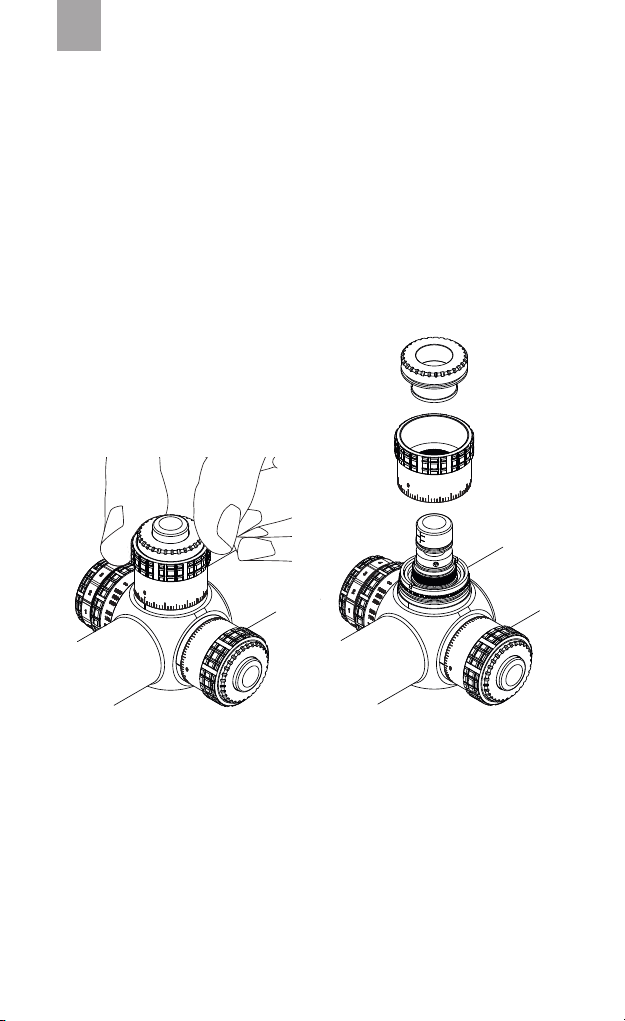
The turrets can have a locking
mechanism to prevent them
being knocked out of position
accidentally. To unlock the turret,
pull it up, and to lock again after
completing your adjustment,
press it down to lock it (Fig. 3).
CAUTION!
Avoid over-tightening the rings. This can damage the scope,
aecting performance or rendering it inoperable. There should
be a slight even gap on the left and right sides of both sets of
rings, between the top and bottom halves. We recommend
tightening the bolts with a torque wrench with a force not
exceeding 1.7-1.8 Nm.
CAUTION!
All discharging of firearms shuold be done at an approved range or
equally safe area. Use of eye and ear protection is recommended.
Zeroing
Fig. 3

EN
9
For elevation adjustment, turn the elevation adjustment screw
clockwise to lower the point of impact and counterclockwise to
raise the point of impact. For windage adjustment, turn windage
adjustment screws clockwise to move the point of impact to the
left and counterclockwise to move the point of impact to the
right . (Fig. 4)
Fig. 4
If a large amount of adjustment is required to align the reticle,
make approximately one-half of the required windage correction,
then approximately one-half of the required elevation correction.
Finish by applying the balance of windage and elevation correction.
Note: one click of adjustment changes bullet strike at a shooting
distance of 100 meters by 0,1 mrad - 10mm on models with
reticles LRD-1T, LRD-1P, DLR-1, or by 0,05 mrad - 5mm on
models with reticles DLS-1, DLS-2, or by 1/8 MOA – 3.5mm on
model with reticle DLS-3

EN
10
Turrets scale zeroing
To realign the zero marks of windage and elevation turrets after
completing the zeroing procedure, you can reset the turret’s
scale to zero.
In the case of the Stryker HD riflescope version with lockable
turrets, to zero the scale, unscrew the ring on the top of the
turret by hand (fig 5). Being careful not to change the position of
the knob, remove the scale and set it so that the „0” point aligns
with the start marker.
Fig. 5

EN
11
Using the zero-lock mechanism
The riflescope is equipped with the „ZeroLock” mechanism that
allows the user to set a lock for the vertical adjustment turret
for specific settings - most often after zeroing the riflescope for
a given shooting distance, e.g. 100m. This mechanism sets a hard
stop on the elevation zero, so the user cannot accidentally be
a whole turn of elevation out when dialling back to zero after
taking a longer shot that required multiple turns of elevation on
the turret.
Unscrew the ring on the top of the turret (fig 5). Then, using a
1.5mm Allen key, loosen the three lock screws located on the
side of the „ZeroLock” locking ring (Fig. 6). After zeroing the
riflescope set the locking ring and fix it by tightening the three
counter screws. Be careful not to change the position of the
turret and then set turret scale so that the „0” point aligns with
the start marker. Finally, replace and tighten the turret scale.
Fig. 6

EN
12
Illuminated reticle
The riflescope has an 11-step adjustment of the illuminated point
(DLR-1, DLS-1, DLS-2, DLS-3 reticles) or point with additional
markers (LRD-1T and LRD-1P reticles). The brightness adjustment
is located on the riflescope’s body on the left next to the turrets,
integrated with the parallax adjustment knob. See figure 8.
The illumination is powered by a 3V battery (CR2032 battery).
When replacing the battery, first unscrew the battery compartment
lid. Remember to insert the battery with the correct polarity.
Power adjustment
To change magnification, simply rotate the magnification ring to
align the desired number on the power scale with the index dot.
The adjustment ring is located between the eyebell and tube of
the riflescope. For your comfort of use, the ring has an additional
lever. (Fig. 7)
Fig. 7
Fig. 8

EN
13
Parallax adjustment
The riflescope is equipped with a side parallax adjustment knob
to adjust focus to the target distance. Targets at any other
distance will be aected by parallax shifts, which manifests itself
as apparent movement of the reticle against a stationary target.
To adjust the parallax, turn the adjustment knob by selecting
the appropriate distance on the scale or by looking through
the riflescope turn the adjustment knob for a sharp image and
a steady reticle when your eye in moved slightly. The parallax
adjustment knob is located on the left side of the riflescope’s
body (fig. 9).
Fig. 9
The range of parallax adjustment beyond infinity allows you to
fine-tune the focus when shooting at long distance.
Optionally, the riflescope can be equipped with a larger parallax
adjustment wheel increasing the precision of settings and
measuring the distance to the target, popular in various air rifle
disciplines.
Sunshade
Stryker HD riflescopes come with a sunshade that increases the
comfort of aiming especially in strong sunlight and also protects
from rain splashes on the objective lens. To mount it, screw it
into the threaded ring at the end of the lens housing.

EN
14
RETICLES CHARACTERISTICS
Stryker HD 4.5-30x56 FFP
LRD-1P, LRD-1T and DLR-1 reticles were designed for ambitious
shooters for PRS and tactical shooting at medium and long
distances. The reticles ensure maximum comfort of shooting
and high functionality throughout the zoom range (4.5-30x).
Their unique features include quick and eective estimation of
distance to the target, wind corrections and moving targets, as
well as quick adjustments at low magnifications. The design of
the reticles allows both the assessment of the distance to the
object of known sizes, as well as correction for bullet trajectory
and windage. The reticles were designed to work in the first focal
plane (FFP) maintaining constant reticle scale over the entire
zoom range. The reticles were scaled in milliradians and are easy
to convert into metric units (1 milliradian = 10 cm per 100m).
LRD-1P
In the center of the reticle there is an illuminated point of
diameter of 0.045 Mil with surrounding, also illuminated,
markers forming a cross. Thin, very precise (0.03 Mil) crosshairs
support aiming. The reticle oers the unique feature of quick
measurements at a level of 0.1 Mil from the center of the
reticle with an accuracy of 0.05 Mil and wind corrections with
an accuracy of 0.1 Mil at a distance of 1 Mil from the center of
the reticle. The horizontal bar at a distance of 7 miles from the
center, as well as the lower vertical at a distance of 12 miles on
the lower vertical bar go into thick bars increasing the visibility of
the cross in dicult lighting conditions, useful especially in the
lower zoom range.
LRD-1T
An extension of the LRD-1P reticle and has been additionally
equipped in the lower section with a set of ballistic markers
for quick adjustments for bullet drop, as well as windage or
derivation adjustments.

EN
15
DLR-1 reticle
There are two main sections of the reticle: the main cross and the side
bar. The cross consists of thick horizontal bars passing at the center of
the cross into thin bars and a thin vertical bar. The lower vertical arm
extends to the end of the field of view, while the upper is shortened
to increase transparency. Thin bars are 0.05 Mil (5 mm) thick and thick
bars 0.4 Mil (4 cm). Bars are divided into markers into 0.2, 0.5 and 1
Mil sections (2, 5 and 10 cm respectively). The center of the cross is
an illuminated point with a diameter of 0.07 Mil (7mm) allowing you to
fire a precise shot even in conditions of limited visibility of the target.
The additional side ruler allows accurate measurement of the target in
the upper zoom range with the accuracy of up to 0.1 Mil (1 cm).
Stryker HD 5-50x56 SFP
DLS-1, DLS-2 and DLS-3 reticles, created especially for long
shots, are the essence of precision and usability. These reticles
are placed in the second focal plane and have been scaled to a
magnification of 40x.
DLS-1
The central point only covers 3mm at 100m distance. The 0.005
Mil thick vertical and horizontal bars have markers spaced at
convenient intervals every 0.2 and 1 Mil (2 and 10 cm/100 m
respectively) to make adjustments for bullet drop or windage.
The DLS-1 reticle, located in the second focal plane, is also
perfect for smaller magnifications around 7-10x, when its center
point is 17-12mm, also due to the convenient day and night
illumination. The reticle is scaled in milliradians (Mil) and is
easy to convert into metric units (1 Mil = 10 cm per 100m) and
corresponds to riflescope clips - 1 click is 0.05 Mil (5mm).
DLS-2
Pure precision. Two thin 0.005 Mil (0.5mm by 100m) lines
intersect in the center at a 90 degree angle. Nothing distracts
the shooter’s sight for an optimal field of view. At the
intersection there is a central illuminated aiming point.

EN
16
CARE AND MAINTENANCE
Your riflescope, though amazingly tough, is a precision
instrument that deserves reasonable cautious care. Do not
attempt to disassemble or clean the scope internally. If your
scope ever does need repairs or adjustments, it should be
returned to the distributor where the device was purchased.
The exposed optical surfaces will perform at their best if they
are occasionally wiped clean with the lens cloth provided or with
an optical quality lens paper like those for eyeglasses or camera
lenses. When cleaning the lenses, first blow away any dirt and
dust, or use a soft lens brush.
Warning! Unnecessary rubbing or use of a coarse cloth may cause
permanent damage to the lens coatings.
Keep the protective lens covers in place when the scope is not
in use.
Maintain the metal surfaces of your riflescope by removing any
dirt or sand with a soft brush so as to avoid scratching the finish.
Wipe the scope with a damp cloth and follow with a dry cloth.
Finally, going over the tube with a silicone treated cloth will
restore luster and protect the scope against corrosion. Be careful
not to touch any of the lenses with the silicone cloth.
DLS-3
Precise reticle, scaled in arc minutes (MOA). The central aiming
point only covers 0.1 MOA (2.9 mm at 100 m). The 0.02 MOA
(0.58 mm) bars have markers spaced at convenient intervals of 1
MOA (smaller) and every 5 MOA (larger) to make adjustments for
bullet drop or windage. 1 click is 1/8 MOA (3.5 mm).

EN
17
Store the scope in a moisture-free environment. Avoid storing
the scope in hot places, such as the passenger compartments of
vehicles on hot days. The temperatures could adversely aect the
lubricants and sealants. A vehicle’s trunk, a gun cabinet or a closet
is preferable. Never leave the scope where direct sunlight can
enter either the objective or the eyepiece lens. Damage may result
from the concentration (burning glass eect) of the sun’s rays.
List of spare parts
• 56mm sunshade DO-2905
• Eyepiece and 56mm lens cover DO-2913
• Zoom lever DO-2932
• Turret cover 4,5-30x56 old design DO-2940
• Turret cover 5-50x56 old design DO-2941
• Turret cover new design DO-2942
Warranty: 10 years

Delta Optical
Nowe Osiny, ul. Piękna 1
05-300 Mińsk Mazowiecki
www.deltaoptical.pl


Table of contents